Note: Descriptions are shown in the official language in which they were submitted.
CA 02495781 2009-05-22
1
Covering Panel
Field of the Invention
The invention relates to a cladding panel for floors, walls,
or ceilings or similar applications.
Related Art
These panels on their side surfaces have tongues and grooves
in order to be able to install these panels in a formation. In
order to achieve a formation as stable as possible it can also be
provided that the panels be cemented to one another.
Summary of the Invention
The priority objective of the invention is to be able to
manufacture panels of the initially mentioned type as easily and
economically as possible, furthermore to enable their storage over
longer time intervals without adverse effects, and finally to make
installation as fast and simple as possible. Another objective is
to prepare a stable, durable and solid surface from the
interconnected panels; during installation alignment of the panels
will be possible over a certain time interval.
As claimed in the invention, in the groove or on at least one
inner surface of the legs of the groove and/or on at least one
surface of the tongue at least one bead or line is applied; a
recess is formed to accommodate it on the surface of the tongue
and/or groove which can be laid down and which is assigned at the
time. The bead acts in this way in the course of installation of
the cladding panels or in the course of their joining; the bead
and the recess interact as locking elements. When the locking
element or the bead is formed with a cement, an adhesive
CA 02495781 2005-02-17
2
connection between the tongue and,the groove can be achieved. The
bead of plastic and/or cement is easily and quickly applied at the
factory, for example sprayed on; in particular the bead is applied
in the groove, with which the bead is protected against damage and
dirt.
A material machining process, for example milling, to form
the locking element, is eliminated.
It is only necessary to form the recess assigned to the bead
in the wall surface of the groove and/or in the tongue surfaces;
the formation of the locking element which interacts with this
recess in the form of a bead is extremely simple. This type of
joining and optionally cementing technique can be used for
cladding panels of any materials, wood, derived timber products,
especially MDF, HDF, chips, etc.
A series of plastics is known which can be applied as a
corresponding bead or line to the surfaces of the groove and/or
the tongue. In particular silicone plastics, plastics based on
polyalkylene, especially PVC, PE, PP, and hot-melt cements based
on neoprene can be used. These plastics should be deformable by
heat or adhesive by heat and it should be possible to extrude or
shape them in bead form and they should be able to solidify
adhering to the respective material of the panel. In use they
should have the corresponding elasticity and viscosity in order to
be able to act as a catch element.
Plastics deformable by heat are especially thermoplastics,
elastomers or thermoplastic elastomers. Thermoplastics can be
polyolefins, vinyl polymers, polyamides, polyester, polyurethane
and ionomers. Elastomers can be diverse types of rubber.
Thermoplastic elastomers are especially TPE, TPR, TPO, SPS, TP-Q,
CA 02495781 2005-02-17
3
TP-U. Plastics can also be hot-melt cements or hot sealing
cements based on ethylene vinyl chloride, PA, PU, EVA. Other
plastics can also be used.
A series of adhesive cements is known which have sufficient
strength in order not to be removed when the tongue is pushed into
the groove or to be damaged in their surface configuration, but as
a result of penetrating atmospheric humidity and/or by application
of water in the course of installation they are activated enough
to fully develop their adhesive action. After hardening of the
cement of the cement bead it acts on the one hand based on the
adhesive action and on the other based on the developed locking
action. The adhesives used will be applicable with a nozzle to
the respective material of the panel and will adhere well there.
These cladding panels have the advantage that the movements
and manipulation steps in installing the panels on site are
considerable reduced; it is simply necessary to introduce water
into the groove with the corresponding expedient and/or to apply
it to the tongue in order to activate the cement, if this is
desired at all. If it is a cement which sets as a result of the
existing moisture in air, this procedure is not necessary.
One special advantage lies in that due to the mass of the
cement placed in the cement bead at the factory, a correctly
dimensioned or sufficient amount of cement is present and handling
or removal of the cement which has been applied in excess at most
or emergence of the cement from the tongue-in-groove joint is
eliminated.
Cements are especially glues which consist of a water-
soluble, animal (glutine, casein), vegetable (starch, dextrin,
cellulose) or synthetic (for example, polyacrylic acid
CA 02495781 2005-02-17
4
derivatives, polyvinyl alcohol, polyvinyl pyrrolidone) polymers
and water as the solvent. They belong to the class of single-
component cold-bonding adhesive cements in which the solvent
(water) during the cementing process is sucked up or escapes.
These glues solidify as they cool, especially jelly-like and
generally dry to a transparent mass which decomposes upon contact
with water into a gel with high adhesive force.
It is preferable if an adhesive which is dispersed in water
or prepared with water or a glue is applied as the cement bead and
dried in situ or at the factory. By applying water at the
consumer directly to the dried adhesive layer or by indirect
intensive contact with water which has been applied to a panel to
be joined or its groove or tongue, or by penetrating moisture,
after the panels are joined to one another the dried cement is
activated and returned to the active, adhesive-ready state. The
application of the aqueous activator can take place by spraying-on
or application by sponge or the like.
In one advantageous approach first the cement beads are
moistened with water or a water film which wets at least the
cement bead as the adhesive activator is applied or sprayed onto
the tongues and/or into grooves of the panels and then the panels
are joined to one another. The availability time of the
reactivated cement is chosen such that there is enough time for
the panels to be joined to one another.
If the bead or line is made of plastic, this embodiment has
the advantage that the groove and tongue can be easily locked to
one another; if the bead or line is formed from an adhesive
cement, locking can take place accompanied by cementing.
CA 02495781 2005-02-17
It is advantageous if the features of claim 4 are
implemented. In this execution of the tongue and groove the
cohesion of two cladding panels to be joined together is improved
and a coating which has essentially considerable stiffness is
5 achieved. In this case the cement of a cement bead can support
the especially intimate connection between the tongue and groove.
It is advantageous if the features of claim 6 are satisfied.
In this way the danger of damage or shearing off of the adhesive
bead or a plastic bead when the tongue is pushed into the groove
is reduced and its hold on the surface to which the bead adheres
increases. In this connection it is advantageous if the cement
bead adheres strongly in this recess and/or to the wall surfaces
of the groove or the tongue surfaces. This strong adhesion is not
to be lost even when the cement is activated by contact with
water, in particular this adhesion is to be made as strong as
possible.
It is advantageously provided that the tongue and groove are
each formed lengthwise and in one lengthwise side and lengthwise
and in one transverse side of a panel, optionally the tongue
and/or groove and/or bead or line extending over the entire length
of the respective side surface. Thus, over all sides of the
cladding panels during installation with the cladding panels to be
joined, an optimum joining capacity and optimum cohesion are
achieved.
Connection of the panels to be joined together becomes simple
when the features of claim 7 are used; the joining of the plane
surfaces is possible with low expenditure of force, it is simply
necessary to overcome the elevations formed by the applied beads
in order to insert them into the recesses. To do this it is
CA 02495781 2005-02-17
6
provided as claimed in the invention that at least one leg,
preferably the lower one, of the groove when the tongue is
inserted can be elastically widened or elastically bent and/or the
plastic and/or cement used has the corresponding elastic behavior
or viscosity.
if the features of claim 10 are implemented, a good
connection of two panels to be joined to one another results, a
connection which can be easily accomplished and which does not
require additional space. The shape of the adhesive bead results
in that it comes into contact with the tongue surface or the wall
surface of the groove of the panel to be joined and thus the two
panels are cemented to one another. Completed elastic widening of
the legs of the groove by the cement bead which is introduced into
the recess is undone again by the cement which becomes softer in
the course of activation; thus the cross section of the cement
bead and the cross section of the assigned recess can overlap to a
certain extent. In this respect the features of claim 21 are
advantageous.
It is provided as claimed in the invention that the cement of
the cement bead or line is water-soluble or can be partially
dissolved and/or activated upon contact with water or with supply
of water and/or moisture and/or, is formed by water-soluble glue,
for example white glue, and/or by a pressure cement or a pressure-
activated cement or one which develops adhesive action when
pressure is applied.
It is furthermore provided as claimed in the invention that
the panel is formed from derived timber products, MDF, HDF,
plastic, recycled plastic, chips with artificial resin or bonded
chips (particle board) and optionally provided with at least one
CA 02495781 2005-02-17
7
coat, for example a decorative coAt, especially of plastic, paper
impregnated with synthetic resin, wood, or the like on its front
or working surface and/or on its back.
The cross sectional shape of the bead can be diverse; it is
advantageous if the bead or line and/or the recess and/or the
recess in cross section has a semicircular, lenticular, elliptical
or elongated-rectangular shape, and/or that the transitions from
the flat surfaces to the recesses and/or to the recesses run
rounded or bevelled.
Good cohesion of two panels to be joined or of the tongue and
groove results when the features of claim 18 are implemented. In
this embodiment the cement bead is reliably in contact with the
parts to be connected, specifically the tongue and groove of two
panels which are to be connected.
It is especially advantageous if as claimed in the invention
the features of the characterizing part of claim 27 are satisfied.
In this way the bead performs a double function, specifically it
acts as a locking element and as an element for joining two
panels. The features of claim 32 are advantageous. With one such
component which is called an outside tongue it is simply necessary
to mill grooves on the peripheral surfaces of a panel; the
components can be quickly produced in large amounts; the
components are joined to the panels in part at the plant or this
remains for the user to do.
In one especially advantageous embodiment of the invention
the grooves and tongues are not pointed perpendicular to the
lateral surfaces of the panels, but run perpendicular to the top
surface of the panels. Thus the tongue and groove can be locked
when the panels are installed by movement which takes place
CA 02495781 2009-05-22
8
perpendicular to the panel surface. Nevertheless all the advantages
of the above described tongue-in-groove connection possibilities can
be used or provided.
Brief Description of the Drawings
The invention is detailed below using the drawings which show
for example schematic embodiments of the invention.
Figures 1 to 9 and 11 to 14 show schematic sections through
cladding panels; Figure 10 schematically shows two cladding panels
being joined to one another; Figure 15 shows one detail of a bead;
Figure 16 shows one embodiment of the invention in which the
tongue is made in the form of an "outside tongue" and is inserted
into the grooves of adjacent panels or panels to be connected; Figure
17 shows one especially advantageous embodiment of the invention.
Figures 18, 19, and 20 show additional embodiments of the present
invention.
Detailed Description of the Preferred Embodiments
Figure 10 schematically shows two cladding panels 1, 2 which are
to be pushed onto one another in the direction of the arrow 20 and
joined to one another. This pushing or joining can take place in the
last step only in the plane spanned by the two panels 1, 2. On their
lengthwise side the two panels each have a tongue 6 which projects
from the face surface 17 and on the opposite lengthwise side a groove
12 which is made in the face surface 17. The same conditions prevail
on the face surfaces 17 of the narrow sides, each of the panels 1, 2
has one groove 12 and one tongue 6 on the face surface 17 of these
narrow sides.
The shape of the tongue and groove are matched to one another in
order to ensure a good connection between the tongue and groove. This
shape allows insertion of the tongue 6 into the groove 12 when the
panels 1, 2 are aligned in the plane of the panels. It is possible
to connect the panels 1, 2 in a
CA 02495781 2005-02-17
9
checkerboard manner or offset against one another. Connection
both on the lengthwise sides and also on the narrow sides takes
place by displacement essentially in the plane spanned by the
panels 1, 2.
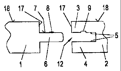
Figure 1 schematically shows a section through two panels 1,
2 which are to be joined. The panel 1 has a tongue 6 which is
inserted into a groove 12 of the panel 2 until the face sides 17
adjoin one another in the upper area or in the area which is near
the top surface 18 of the panels 1, 2. The boundary edges of the
groove 12 can be rounded or bevelled.
On at least one tongue surface, in this case the tongue
surface 7 near the top surface, a bead 8 is applied or adheres
especially strongly to the tongue surface 7. At one location of
the wall surface 5 of the groove 12 or of the leg 3 near the
surface, which location is assigned to or corresponds to the
joined panels, a recess 9 is formed which is matched in its cross
section to the bead 8 in the otherwise plane wall surface 5. When
the two panels 1, 2 are joined or when the tongue 6 is inserted
into the groove 12 the bead 8 comes to rest in the area of the
recess 9 or can engage this recess 9. Advantageously it is
provided that the cement of the cement bead or line 8 is water-
soluble or upon contact with or upon supply of water and/or
moisture can be partially dissolved and/or activated and/or is
formed by water-soluble glue, for example white glue, and/or by a
pressure cement or a cement which can be pressure-activated or
which develops adhesive action when pressure is applied.
Activation of the cement of the cement bead 8 can take place by
wetting the cement bead 8 with water before the panels 1, 2 are
joined or by introducing water into the groove 12 or into the
CA 02495781 2005-02-17
recess 9. Depending on the choice of the cement it can also be
provided that after engagement of the cement bead 8 with the
recess 9, the atmospheric humidity when penetrates in the use of
the panels 1, 2 activates the adhesive capacity of the cement bead
5 8 and thus an adhesive connection between the tongue 6 and the leg
3 of the groove 12 is established. Fundamentally cements could
also be used which can be activated with substances other than
water.
For joining panels 1, 2, in this case for inserting the
10 tongue 6 which is provided with the bead 8 into the groove 12, it
is provided as claimed in the invention that at least one leg 3, 4
of the groove 12 can be elastically widened or elastically bent up
when the tongue 6 is inserted.
Fundamentally it is possible to form at least one or more
beads (8) and/or recess(es) 9 which are parallel next to one
another on one or both tongue surfaces 7 or on one or both wall
surfaces 5 of the groove 12. It must simply be watched that a
corresponding recess 9 at the corresponding location in the wall
opposite it is assigned to each bead 8.
Accordingly, in Figure 2 two beads 8 which have been applied
to the tongue 6 are formed; at the corresponding location on the
wall surface 5 of the groove 12 two recesses 9 correspond to these
beads 8. In this way cementing and/or locking of the tongue and
groove can be improved.
In one embodiment as shown in Figure 3 it is provided that
the two tongue surfaces 7 converge toward the free end of the
tongue 6 and that the wall surfaces 5 of the groove 12 are tilted
at the same angle as the tongue surfaces 7 and converge to the
outside.
CA 02495781 2005-02-17
11
It can apply to these and &lso all other embodiments that
advantageously the tongue 6 and the groove 12 can be connected by
form-fit or with a snug fit at least over part, optionally over
the entire insertion area of the tongue 6 and/or that the area of
the tongue 6 which is located in front of the bead or line 8 or
the recess 9 toward the free end of the tongue 6 can be inserted
into the groove 12 by form-fit or with a snug fit. In all
embodiments it can be provided that the tongue 6 and/or the groove
12 and/or the bead or the line 8 extend over the entire length of
the respective side surface 17 and/or that the bead or line 8 and
optionally the recess 9 and optionally the recess 10 extend
continuously over the length of the groove and/or the tongue 6 or
are applied or formed in the form of individual successive
segments.
As the material of the panels as claimed in the invention it
is advantageously provided that the panel 1, 2 is formed from
wood, derived timber products, MDF, HDF, plastic, recycled
plastic, chips with artificial resin or bonded chips (particle
board) and optionally is provided on its front or working surface
and/or on its back with at least one coat 13, 14, for example a
decorative coat, especially of plastic or paper impregnated with
artificial resin. Furthermore it can be advantageously provided
that the groove 12 and the tongue 6 are made of the material of
the panel 1, 2 or are milled out from it, or that the tongue 6 is
formed in one piece with the material of the panel 1,2. In all
embodiments and also in the embodiment as shown in Figure 3 it can
be provided that the bead(s) or line(s) 8 can be locked to the
assigned recess(es) 9 in the tongue 6 and/or in the groove 12 and
CA 02495781 2005-02-17
12
the bead(s) or line(s) 8 and recess(es) 9 interact as locking
elements.
In one embodiment as shown in Figure 4 it is provided as
claimed in the invention that on one wall surface 5 of the groove
12 a bead 8 is formed; at the corresponding position on the tongue
surface 7 a recess is formed for accommodating the bead 8. Thus
both locking and also cementing of the two panels 1, 2 which are
to be joined to one another are possible.
In the embodiment as shown in Figure 5 it is provided that on
the tongue surface 7 near the top surface a recess 9 is formed and
that on the tongue surface 7 away from the top surface a bead 8 is
applied. Accordingly, on the wall surface 5 of the leg 3 of the
groove 12, i.e. the wall surface near the top surface, a bead 8 is
formed and on the wall surface 5 of the leg 4 a recess 9 is
formed. As can also be seen from Figure 5, the bead 8 and the
recess 9 can be assigned to one another in terms of location in
order to enable corresponding locking and optionally cementing.
In the embodiment as shown in Figure 6 it is provided that on
each tongue surface 7 two recesses 9 at a time are formed at a
distance from the face surface 17 of the panel 1; accordingly, in
the wall surfaces 5 of the legs 3 and 4 two beads 8 are formed at
a time at the corresponding interval or at the corresponding
distance from the face surface 17 of the panel 2.
It can be provided as claimed in the invention that part of
the bead or line 8 is located countersunk in a recess 10 which is
made in the wall surface 5 of the groove 12 and/or in the tongue
surface 7. The recess 10 also helps to join the applied bead 8
securely to the respective wall surface and also when the tongue 6
is inserted into the groove 12 to prevent it from being sheared
CA 02495781 2005-02-17
13
off. As shown in Figure 15, the bead 8 can also extend over the
recess 10 to the surfaces 5 or 7.
The panels 1, 2 can be provided with coats 13 and 14 of for
example wood, plastic, paper or the like in order to configure the
working surface or the bottom surface accordingly. These coats
however do not have any effect on the connecting technique as
claimed in the invention.
The selected cross sections of the recesses 9 and the
recesses 10 or the beads 8 can be chosen at will; the area of the
bead 8 projecting out of the recess 10 or over the wall surface 5
of the groove 12 or the tongue surface 7 is accommodated by the
recess 9 and comes into contact with their surfaces and optionally
cements the tongue 6 to the legs 3, 4 of the groove 12. The cross
sectional shape of the recesses 9 can be elongated-rectangular,
triangular, lenticular, triangularly elliptical or the like.
Fundamentally, as also shown in Figure 11, the recess 9 can
be formed by a row of recesses which are located directly next to
one another and which together constitute the recess 9. In this
case the corresponding shaping of the bead and/or corresponding
water application for the cement bead 8 can be provided or this
cement bead can be partially dissolved accordingly so that it
softens enough and can assume or fill the cross sectional shape of
the recesses 9. Alternatively the plastic of the bead would have
to have the correspondingly high elasticity or viscosity.
It should be fundamentally avoided that the legs 3, 4 of the
groove 12 which are elastically widened when the tongue 6 is
inserted into the groove 12 remain in the widened position. In
the widened state the joint 16 between the surfaces 18 of the two
panels 1,2 would form a step which would be subject to increased
CA 02495781 2005-02-17
14
wear. In one especially advantageous embodiment of the invention
it is provided that the leg 3 of the groove 12 near the top
surface is made more or less elastic, especially inelastic
overall, and only the leg of the groove near the bottom or the
lower leg is made to be elastically deflected. In this way it can
be avoided that the upper leg 3 near the surface is bent up by
more or less deformable beads 8, but only the lower weaker or
thinner leg 4 of the groove 12 is bent. Advantageously, to prevent
the upper leg 3 of the groove 12 from being bent up it can also be
provided that the bead(s) 8 is (are) made only on the tongue
surface 7 pointed down or on the wall surface 5 of the lower leg 4
of the groove 12. In this way both the tongue 6 and also the upper
leg 3 of the groove 12 would counteract arching of the connecting
site when the extent or volume of the bead is made too large or
when using a cement it is not made soft enough and the volume
provided for it is not enough.
The shape of the recess 10 can be lenticular, triangular,
semielliptical or elongated-rectangular; it is provided that this
recess 10, like the recess 9, is made as a depression in the
otherwise plane tongue surface 7 or the plane wall surface 5 of
the groove 12. Thus the application of cement or the amount of
plastic for the bead 8 will be defined or limited to certain
areas.
In the embodiment as claimed in the invention as shown in
Figure 8, it is provided that in the tongue surfaces 7 of the
tongues 6 recesses 10 are formed which each accommodate one bead
8. The two beads 8 have different cross sections. It is quite
possible to make the beads which are located in the two wall
surfaces 5 of a groove 12 or on the two tongue surfaces 7 of a
CA 02495781 2005-02-17
tongue 6 differently; accordingly then also the recesses 2 which
accommodate the beads must be made differently. In the case of
Figure 8 the recess 9 made in the leg 3 is larger than the recess
9 which is made in the leg 4.
5 It can be advantageous if the front edge areas of the tongue
6 have curves or bevels 19, as is shown in Figure 1, 3, and 7 and
8 in order to be able to displace the legs 3, 4 or the beads 8 as
carefully as possible away from one another when the tongue 6 is
inserted into the groove 12.
10 In the embodiment as shown in Figure 9, it is provided that
the cement beads 8 which are formed on the wall surfaces 5 of the
groove 12 have a vertical extension H which exceeds the common
depth of the recess 9 and the recess 10. In order to achieve a
joint-free surface connection here or to prevent a residual
15 widening of the groove, there is a cement which becomes soft by
absorbing water or by being wetted with water such that it deforms
and fills the free space 23 in the recess 10 and the free space 23
of the recess 9.
In the embodiment shown in Figure 12, it is provided that the
bead 8 which has been applied in the recess 10 in the wall surface
5 of the groove 12 overlaps with respect to its cross section with
the cross section of the preferably triangular recess 9 which is
located in the facing tongue surface 7 of the tongue 6. The
overlapping areas 21 are softened accordingly for cement beads by
activation of the cement of the cement bead 8 with water so that
the cement bead 8 can adapt to the shape of the recess 9 with
simultaneous cementing and locking of the two panels 1, 2 which
are to be connected to one another. For plastic beads the plastic
would have to have the corresponding viscosity.
CA 02495781 2005-02-17
16
Figure 14 shows beads which have recesses 10 which have
different cross sections in comparison to one another and which
are provided in recesses 10 which are made differently in
comparison to one another in the two wall surfaces 5 of the groove
12, especially cement beads or lines 8 which interact with
recesses 9 which are different from one another and compared to
the cement beads 8 in the tongue surfaces 7 of the tongues 6.
As can be seen in Figure 14, the tongue 6 can have
fundamentally or in all embodiments a curve 24 directly in front
of the recesses 9. Thus it also becomes possible to make the
tongue 6 shorter and the groove 12 less deep. Furthermore, it is
shown in Figure 14 that the joint 16 in the area of the panels 1,
2 near the surface is made such that the areas of the face surface
17 which are near the top surface adjoin one another and a gap is
avoided as much as possible. In the area of the panels 1, 2 near
the bottom or away from the top surface it is provided that the
face surfaces 17 do not touch one another and that a gap 15 is
formed in between. This is achieved especially in that the leg 4
of the groove 12 near the bottom is made slightly shorter than the
leg 3 near the top surface.
It is generally advantageous if the bead or the line 8 is
applied in the middle to the tongue surface 7 or to the wall 5 of
the groove 12 or of the legs 3, 5.
The different dimensions of the bead, especially a cement
bead 8, and the groove 12 are plotted in Figure 13. Information
relating to advantageous embodiments of beads, especially cement
beads, is given by this figure.
It can be provided as claimed in the invention that the width
B of the bead or line 8 is twice to nine times, preferably twice
CA 02495781 2005-02-17
17
to seven times, especially three to seven times, as great as its
height. Furthermore, as claimed in the invention it can be
provided that the cement bead or line 8 comprises an adhesive-
latent cement material, preferably a polymer cement which can be
emulsified with water, and the cement material can be converted by
wetting with water into the adhesive-ready or adhesive state
and/or that the plastic or the cement material of the cement bead
or line 8 which can be (re)activated with water or moisture is
applied with an essentially uniform layer thickness from 0.1 to
0.6 mm, especially from 0.2 to 0.5 mm, at thickness tolerances in
the range of 0.05 to 0.1 mm and/or that the cement of the
cement bead or line 8 is formed by a quick-setting or mounting
glue based on polyvinyl acetate, such as for example Dorus MDO 55
from Henkel, or by a commercial wood glue, for example based on
starch or protein. It can be advantageous if the width B of the
cement bead or line 8 corresponds to 5 to 25W, preferably 9 to
21%, especially 12 to 17% of the thickness D of the groove 12.
It should be noted that the beads 8 can be attached to the
corresponding surfaces 5, 7 either directly on these surfaces 5, 7
or in the recesses 10 which were formed in the especially plane
surfaces 5, 7. Advantageously the applied beads 8 project roughly
0.2 mm over the respective surface 5, 7. The recesses 9 which have
been formed for holding the cement beads 8 have a depth of
advantageously a maximum 0.3 mm. It is especially advantageous if
roughly triangular recesses 9 interact with the beads 8 which are
lenticular in cross section. In this respect reference is made to
the embodiment of Figure 12.
CA 02495781 2005-02-17
18
Advantageously the tongue 8 on each tongue surface 7 has a
recess 9 and a cement bead 8 is applied to each leg 3, 4 of the
groove optionally 12 in a recess 10.
The significant effect of the applied bead is its locking
action which is used especially in the course of installation and
matching of the panels to be joined.
With the corresponding rounding of the edges of the free end
of the tongue 6 and/or rounding of the inside edges of the wall
surfaces 5 of the legs 3, 4 of the groove 12 it is possible during
installation to place the panels 1, 2 to be joined to one another
first at a certain angle on one another in order to achieve entry
of the tongue 6 into the groove 12 to a certain extent. The final
locking of the tongue 6 and groove 12 or the last locking step
which ends with contact of the face surfaces 17 in the area near
the top surface is possible only when the panels 1, 2 are pushed
relative to one another in the plane of the panels.
Fundamentally, it is also possible to apply cement in excess
and to make the cross section of the cement bead 8 larger than the
cross section of the recess 9. In this case the cement which has
been softened by the solvent, especially water, would enter the
gap between the groove and the tongue. This could be advantageous
for the strength of the tongue-in-groove connection. But care
should be taken that the cement is softened or becomes soft
accordingly, so that in the joint area of the panels 1, 2 to be
joined to one another no unevenness is formed. The amount of
cement to be applied in the cement bead 8 thus depends on the
geometrical circumstances between the tongue 6 and the groove 12
and on the size of the recesses 9 and 10 and especially also on
the viscosity of the reactivated cement.
CA 02495781 2005-02-17
19
Figure 16 shows one embodiment of the invention in which the
tongue construction is made such that the side surfaces 17 on
which the panel 1, 2 should have a tongue which is-designed to
interact with the groove of the panel to be connected are made
such that first a groove 12 is formed there into which a tongue 6'
of an independent component can be inserted. This tongue 6' as an
independent component takes the place of the tongue 6 described in
the figures and the specification and claims and is joined or can
be joined to the panel 1, 2 optionally at the factory. The tongue
6' is made along its two sides like the tongue 6 and is made on
both sides as is descried in conjunction with the specification,
drawings and claims for a tongue 6. It can be provided that the
tongue is made mirror-inverted. With one side the tongue 6' is
inserted into the groove of the panel 1 and with the other side
into the groove of the panel 2. In doing so the beads 8 and/or the
recesses 9 on the tongue surface 7 lock with the recesses 9 and/or
beads 8 in the legs 3, 4 of the respective grooves 12.
The component constitutes a doubled tongue 6. The advantage
of the so-called outside tongue is that the panels 1, 2 can be
made all-around with the corresponding grooves 12 on their side
surfaces and the outside tongues can be inserted into the grooves
12 at the factory or only when being installed. The insertion of
an outside tongue 6' also takes place in the plane of the
respective panel 1, 2. The panels 1, 2 are also joined when using
outside tongues 6' at least in the last joining step by
displacement in the plane of the panel.
All details for the tongues 6 apply both to the left part and
also the right part of the component 6' shown in Figure 16.
CA 02495781 2005-02-17
Figure 17 shows one embodiment of the invention in which the
grooves 12 are made perpendicular to the side surfaces 17, but run
turned perpendicular to the top surface of the panels 1, 2, i.e.
turned by 900. The groove area A is formed or made in the same way
5 as grooves 12 which are described in Figures 1 to 16 or the
pertinent description and the pertinent claims. A tongue 6 which
likewise corresponds to the tongues 6 interacts with this groove
12, and they have been described in previous Figures 1 to 16 and
in the preceding description and the claims. The tongue 6 can
10 likewise be viewed turned by 90 . The area A is thus simply the
hitherto described connecting area of the groove 12 to the tongue
6, only that in this case the groove 12 and the tongue 6 run
perpendicular to the top surface of the panels 1,2. Therefore
connection of the panels 1, 2 takes place, not by displacement in
15 the plane of the panel, but by displacement perpendicular to the
surface of the panels 1, 2. The panels cannot easily swivel in;
in the final step of joining movement takes place perpendicular to
the plane of the panel.
As already described above in conjunction with Figures 1 to
20 16, on the wall surfaces 5 of the groove 12 and/or on the tongue
surfaces 7 recesses 9 and/or beads 8, especially cement beads, are
formed in order to accomplish mutual locking of the groove 12 to
the tongue 6 and at best mutual cementing.
Furthermore, the area B which is made in the panel 2 can be
defined as a groove area turned by 90 in the sense of the
preceding description and Figures 1 to 16 and the claims. The leg
4 of this groove area B interacts on the one hand as the tongue 6
with the groove 12 of area A; however on the other hand the leg 4
with the body 31 of the panel 2 also forms a groove 121 into which
CA 02495781 2005-02-17
21
the leg 4 of the area A can be inserted. One or both sides of the
leg 4 can be provided with beads 8 and/or recesses 9 which
interact with beads 8 and/or recesses 9 made in or on the wall
surfaces 5' of the groove 12'. The execution of these beads 8 and
the recesses 9 in the groove 12 and/or on the tongue 6 was already
detailed in the preceding description.
To the extent it is provided that the panel 2 in its lateral
end area ends with a boundary surface 30 at a distance from the
outside leg 4 of the groove 12 in order to facilitate joining of
the panels 1, 2, the corresponding beads 8 and/or recesses 9 are
provided only on the tongue 6 which can be inserted into the
groove 12 of the area A of the panel 1.
The leg 3 of the tongue 12 in the panel 1 is integrated into
the body of the panel 1 or is constituted by the panel body.
The beads 8 can in turn be located in depressions 10; in
Figure 17 these depressions 10 however are not drawn. The above
described cements and/or plastics are used for the beads 8.
The grooves 12, tongues 6, recesses 9 and 10 are preferably
producing by milling.
Patent Claims: It is advantageous if at least one bead
extends parallel to or along the edge of the face surface 17 or in
the longitudinal direction of the panel 1, 2. In principle, the
track of the bead can deviate-either as a result of production
factors or deliberately-from a parallel path in relation to the
longitudinal extent of the panel.
As is shown in Figure 18, the recess 9 on the tongue 6 has an
attachment or contact surface 60 for the bead that is proximate to
the panel 1 or, as in Figure 19, the recess 9 in the groove 1 has
an attachment or contact surface 60 for the bead 8 that is
CA 02495781 2005-02-17
22
proximate to the bottom of the groove. These surfaces 60 act
together with the bead 8 or lock together with the it and prevent
the tongue 6 from moving out of the groove 12. The surface 60 can
be inclined relative to the surface of the panel 1, 2 (as
indicated by the broken line in Figure 19) or be perpendicular to
it.
In Figure 18, the recess 9 extends on the tongue 6 from the
contact surface 60 as far as the face surface of the panel 1, 2
and, in Figure 19, in the groove 12 from the contact surface 60 to
the base of the groove. The recess 19 is of the same size or
greater than the volume of the bead 12 that it is to accommodate.
Adhesion of the bead 12 can be effected with the surface 60 and/or
with the inner surface or with part-areas of the inner surface of
the recess 9 that is opposite the bead 12.
Figure 20 shows cladding panels 1, 2 that can be joined to
one another by a turning motion and by being moved toward one
another. As is shown in the lower part of Figure 20, the panel 1
has a groove 12, the inner surfaces of which are curved. The
tongue 6 of the panel 2 that is to be joined to it has tongue
surfaces that are matched to the curvature of the side surfaces of
the groove. The thickness of the tongue 6 corresponds to the
width of the groove 12.
In the present case, the tongue has at least orie bead or line
on its tongue surfaces, and this can be introduced or snapped into
matching recesses 9 in the side surfaces of the groove.
The panels 1, 2 can be joined together as is shown in the
upper part of Figure 20. The panel that is to be joined is set
obliquely on a panel that has already been installed, and the end
part of the tongue 6 is inserted into the groove 12. Then, the
CA 02495781 2005-02-17
23
panel 2 is lowered or pivoted downward, when the tongue 6 is
inserted into the groove 12. At the same time, the panels 1, 2
move closer together. In the final stage of the joining movement,
the beads 8 snap together with the recesses 9 and lock the join
that has been made. Figure 20 shows diagrammatically three
positions of the panel 2 that is to be joined. In the uppermost
position (indicated by the broken line), the panel that is to be
joined is in a position in which the tongue 6 has been partially
inserted into the groove 12. When the panel that is to be joined
is pivoted further downward, as is shown in the middle position
that is shown, the tongue 6 moves still further into the groove 12
until in the joined position at least the surface face areas of
the panels 1, 2 lie against each other and the tongue 8 is held in
the groove 12 to the extent that the beads 8 correspond or
interact with the recesses 9. This also applies when the position
of the beads 8 and the recesses 9 are exchanged.
It is advantageous of the radii of curvature of the inner
surfaces of the groove 12 as well as of the surfaces of the tongue
6 are of equal size or that the thickness of the tongue 8
corresponds to the width of the groove 12.
In general, it is advantageous if the beads 8 lie directly
opposite one another relative to the tongue 8. The same applies
to the beads 8 on the inner surfaces of the groove 12.
Accordingly, the recesses lie opposite one another.
It is possible to form beads 8 and/or recesses 9 that
interact with one another on the curved side surfaces of the
grooves.
It is also possible that the surfaces of the tongue and the
side surfaces of the groove 12 incorporate straight or curved
CA 02495781 2005-02-17
24
sections, the straight sections not hindering and permitting the
panel 2 that is being installed from pivoting when two panels 1, 2
are being joined.