Note: Descriptions are shown in the official language in which they were submitted.
CA 02496102 2000-04-20
CASINQ CLAMP '
~i~,id of tfie inv ,nl~jan:
s The present invention relates to a device for driving and handling a
drilistring, and, in
particular, far manipulating a casing string in a casing drilling environment,
i~f~kg~round of the rove io °
:o The drilling of wells, such as those 'or oil and gas often use a top drive
to turn the
drillstring. Tire quill of the top drive typically threads into the box end of
the top Joint of
pipe used fur drilling and in turn drives the pipe. The problem encountered is
that there
is potential for damage to the threads of both the drill pipe and the top
drive quill.
Galling of the threads is undesirable; since they have to be machined to
correct the
13 damage, which is time consuming a.nd costly, especially glvorr the
typically r~mote
locations that wells are drilled in. it is especially desirable to avoid
damaging the
threads on the top drive, since they are much mare difficult and expensive to
repair
than drill pipe.
2~ With the development of drilling With casing, that is using a casing string
as the drill
pipe, the issue of thread protection has become much mare important, This is
because the thread form used in casing connections is more fragile than the
connections used in drill pipe, and the casing connections have: to remain
f!~.~id and
pressure tight once the drilling process has been completed. Other
considerations are
2s that casing typically has a thinner side~wail and is less robust than drill
pipe. This is
especially true in the thread area, where the casing has thre2~ds an both
ends, 4vith a
corresponding r~ductian in section area.
While some clamps are available for gripping casing, these clamps grip the
casing ort
3o the inside using expandable jaws. These clamps are therefore not suiteblc
for use ir;
manipulating casing during a casing drillir;g operation. The rxpandabs'e jaws
create a
severe restriction on the casing's inner diameter wni;,h restricts mud flaw
dow:~hoie,
CA 02496102 2000-04-20
2
for example, to a dounhofe motor which may restrict the amount of power the
motor is
capable of producing. In addition, the jaws are not fail safe, since a biasing
aget-~t must
be ccmtinuo~rsly applied to maintain gripping forc~. Prior casing clamps had
na
means for passing fluids to the casing bare and had no means for manipulating
the
s casing sirr~ultaneousiy in vertical and rotational dire~ions.
Other prior methods of h2~ndling casing involved using the kelly or top drive
to turn the
casing, with ttie attendant risk of damage to the threaded Connections. A
safer and
more efficient system of driving a casing string is needed,
~o
;~ m a ~of ~,e inve~ttion:
The present invention provides a clamp for driving a drillstring where the
driltstring is
formed of casing pipe. While the clamp is described herein exclusively for use
with
i < casing, it should be understood that the clamp might be used in other
applications. By
utilising a casing clamp device of the present invention, the risk of damage
to the
threaded connection on the ends of the casing is minimised. The clamp indudes
a
sealing element to enable driEling mud to be pumped down the centre of the
pipe while
rotating the pipe during drilling operations. In addition, the olamp permits
ao simultaneous di$pfacer,~ent of the pipe, either up ar down, while rotating
it, which is an
essential requirement of dri6l~ng.
In accordance with a broad aspect of the present invention, there is provided
a clamp
for use with a top drive for gripping and turning a drifiatring formed of
pipe, the clamp
s: comprising: slips positioned to grip the pipe, drive method for moving the
slip blocks
and dies radiaily inwardly into a pipe gripping position and radially
outwardly to a pipe
releasing position, and an attachment method for connecting the apparatus to a
top
drive.
3o The slips are preferably farmed, for example including a toothed or
otherwise knurled
face, to enhance their engagement against the outer surface of a pipe. The
slips can
be replaceable to accommodate different sizes of pipe and to enable the
gripping
CA 02496102 2000-04-20
surface to be renewed as it wears In one embodiment, the slips carry slip
dies. The
slip dies are selected to engage a pipe disposed between the slips and,
therefore, can
be roughened o~ formed with teeth to enhance their engagement with the pipe
outer
surface. The slip dies can be carried on the slips in such a way as to be
replaceable.
s
in one embodimFnt, the slips am mounted in a slip bawl and are constrained to
mcwe
along a conical taper of the slip bawl to, thereby, be moved radially inward
and
outward relative to the wntre axis of the slip bowl. This permits the slips to
be moved
to grip or reic~ase a pipe positioned t!~erebetween. The conical taper is
positioned to
~o taper down~~ardiy such that as the weight on the pipe increases, the slips
will be
driven to k.~itn with increased force into the pipe.
The drive method can be any suitabGa means far moving the slips radially
inwardly and
outwardly" fcr example, in one embodiment along the taper of the slip bowl. in
one
rs embodiment, tY~e dri~,re r~~ethod includes a biasing agent such as, for
example, a
plurality cf springs that bias the slips down the taper of the slip bowl such
that they ate
normally in d pipe gripping, closed position, Thus, unless a farce is applied
against the
pressure in the biasing agent, the slips remain in a pipe gripping position
reducing the
chance c~f a ripe being inadvertently released. In order to move the slips to
an open
zu position to release a pipe, the drive method includes a system for applying
force
against 'hQ biasing agent. The system for applying force can, for example, use
hydraulics.
The clamp is attached to a top drive by an attachment method. The attachment
25 method is selected to be capable of transferring torque from the top drive
to the clamp
to cause it to rotate. In tine embodiment, a quill adapter is connected to the
clamp and
formed at its outboard end fUr engagement to the quill of the top drive.
1n rune embodiment, the clamp includes a stabbing spear extending ouf to fit
into a
~o pipe and align if with the slips to facilitate grippi;rg. In another
embodiment, a drilling
fluid conduit ~s provided for conducing a flow of drifting fluid into the
longitudinal bore
of the pipe. Preferably, the stabbing spear is formed as a conduit so that It
can also
CA 02496102 2000-04-20
4
serve as the drilling fluid conduit. In such an embodiment, the stabbing spear
includes
seals for acting between the spear and the pipe for restricting the flow of
drilling fluid
outside of the pipe. The spear also acts a$ a mandrel, enhancing the casing's
ability
to vrithstand large inward clamping forces without deforming the pipe.
When the clamp is rr~tated, the slips rotate therewith and; therefore, any
pipe gripped
by the slips is also rotated.
In accordance with arzother broad asper~t of the present invention, there is
provided a
n method for drilling a well with a well casing as an elongated tubular drill
string and a
drilling assembly retrievable from the lower distal end of the drill string
without
withdrawing the drill string from a wellbore being formed by the drilling
assembly, the
method comprising: providing tire ~~asing as the drill string; providing a
drilling
assembly connected at the distal end of the drill string and being retrievable
through
t5 the longitudinal bore of the drill string; gripping the drill string on its
outer surface;
inserting the drill string and the drilling assernbly into the wellbore and
driving the
drilling assembly to operate to farm a wellbore to a diameter greater than the
diameter of tha drill string,
~o Preferably the method further includes: removing at least a portion of the
drilling
assembly from the distal end of the drill sting and moving the at least a
portion of the
drilling assernbly out of the welibore through the drill string without
removing the drill
string from the welibore, leaving the drill sf~ing in the wellbvre.
25 The drilling assembly can be any assembly useful for drilling a wellbore
through an
earth formation. As would be appreciated, the drilling assembly Can include a
drill bit
and any of, for example, measurement while dritling equipment and a downhole
molar.
~o In a preferred embodiments the step of gr ipping the drill string is
accomplished by
providing a clamp according to the present in°~ention as described
hereinbefore.
Preferably. the method further comprises, after the step of inserking; pumping
drilling
fluid through the longitudinal bore of the drill string. fn one preferred
embodiment,
tE;e drill string is gripped and rnnved upwardly or do4vnwardly while being
rotated.
;$
CA 02496102 2000-04-20
Brief descrisitian of the rawirsgs~,
A tur'ther, detailed description of the invention, briefly described above,
will follow by
reference to the following drawing of a specific ernbodirnent of the
invention. This
3 drawing depicts only a typical embodiment of the invention, and is therefore
not to be
considered limiting of its sr.,ope. In the drawings:
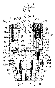
Figure 1 ,4 a crass sectional view through a casing clamp according to the
prESent
invention with the slips (to facilitate understanding only two slips one
shown) in the fully
: o retracted position, useful during insertion or removal of casing from the
clamp.
Figure 2 is a view of the casing clamp of Figure 1 with the slips closed upon
a piece
of .c acing and ready to drill.
Figure 3 is an end view of a slip die useful in the present invention.
Figure 4 is a plan view of the slip die of Figure 3.
is Figure 5 Is a cross sectional view through another casing clamp including a
stabbing
spear.
p,~taifed Dgsgr~ption o,~the Present invention:
zo TEye drawing figureC are not necessarily to scale, and certain features are
shown in
generalised form in the interests of clarity,
As shown in Figures 1 to ~. casing clamp 10 according to the present invention
is
formed to grip a pipe 11 (Figure 3) and to be carr7ed on a top drive (not
shown) s~,ch
zs as, for example, a model no HMI X00 available from Tesco Corporation. The
pipe is
a portion of a drill string formed of casing. The casing clamp sewer as a load
path to
transfer the weight of pipe 11, and the remainder of the drill str ing
extending therefrom,
to th;~ top drive and to transmit the full torque applied from the top drive
to the pipe and
therethro~gh to the drilistring.
ao
Casing clamp 10 includes an autQr housing 12 having a central axis 13. A quill
adapter 1~ is attached to outer housing 12 at its top end and is pos;tioned
coaxialiy
CA 02496102 2000-04-20
6
with rentrai axis ~! 3. At its outbvarcr end 14a, quilt adapter 14 is threaded
for threaded
connection to a top drive quill snot shownj. The casing clamp is supported by
the top
drive through uuili adapter 14..
s Housing 12 includes an opening 12a to accept and facilitate posifionfng of
the quill
adapter in the housing during assarraly Cuill adapter 14 is attached via bolts
15 to
housing 12. Bolts 15 thread through aligned hales in pausing 92 and quill
adapter 14.
Bolts 15 finally engage in threads formed in inner piston housing 2Z3 disposed
vdithin
the housing, ire this mounting arrangement, quill adapter 14. is mounted
between outer
to housing 1?_. and inner piston housing 28.
A slip bowl 1B is rigidly connected to the lower ~:nd of housing 12 by means
of incating
dowels 18. Slip taowl 18 defines a centre! conical bore 17 That is concentric
with central
axis 13. Conical l5are 17 is tapered downwardly to define, tar example, a 4:12
ratio
~s taper between the opposing slips, or 2:12 taper for each individual slip.
While only two dowels 1 S are shown, preferably there are eight dowels spaced
about
the periphery of the slip bcwi. Dowels 18 are removable to facilitate removal
of the slip
bawl from housing 72. Dowels '18 are formed 'o transfer any weight on the slip
bowl tc
2o housing 12. This weight is in turn transferred to the top drive.
Slips 20 are mounted in spaced apart relation about slip bowl 1G. Although
only two
slips are shown, in the preferred embodiment there are 8 slips. The slips are
wedge
shaped having substantially flat faces 20a and sloping bac>C surfaces 20b
which
2s conform to the taper of conical bore 17. Slips 20 arr~ rnaunted in the slip
bawl by dove
tailed slots 21 which accept correspondingly shaped extensions 22 formed on
the
back of the slips. Dove tailed slots 22 extend vertically to permit the slips
mounted
therein to ride upwardly and downwardiy along the taper of the canicai bore
and to,
thereby, move radially toward or away frCm central axis 13. When the slip s 2Q
are fit
3o into their slots t1 they can ride afcng thp taper but ar$ subsf~3;~tialy~
prsv~nted frnm
rotating relative to the slip bG~~l abaut the central axis. Ta provide fvr
lu'arication of the
slips, a grease nipple is ; rowided in a bore 23 opening i~yto each slat 21.
CA 02496102 2000-04-20
7
Slips 20 are prevented from dropping out of slots 21 by attachment to a ring-
shaped
push plate 24. Push plate 24 abuts against the upper surface of slip bowl 16
Ilmiting
the extent to which slips 20 can move downwardly in their slots. Slips 20 are
siidabiy
s mounted in slots 25 formed it the push plate and connected to the push plate
24 by
means of bolts 68. The bolts are formed to secure the slips from moving along
axis i3
" relative to push plate 24, while allowing the slips to move relative to the
push plate
radlally inwardly and outwardly to accommodate the movement of the slips on
the
taper. Bolts 6B are accessible through apertures 72 in outer housing 12 when
the
io slips are In the fully extended position. Also accessible through the
apertures T2 are
grease nipples 76 for applying grease to slots 25 to lubricate movement
between the
slips and the push plate,
Push piste 24 is connected to a drive means far moving the slips along thr~ir
slats. !n
is the illustrated embodiment, the drive means inatudes an annular ram 26 onto
which
push plate 24 is connected as by bolts or welding.
Annular cam 28 extends out from and is selected to ride within a torus shaped
chamber 34 defined between housing 12 and inner piston hauslng 28. Chamber 34
zo contains a plurality of compression springs 30 which act between housing 12
and
annular ram 26 to bias the annular tern downwardty toward push plate 24, in
one
embodiment, ten compression springs are spaced apart within the chamber.
Annular
ram 26 is prevented from being forced completely out of chamber 34 by abutment
against an annular Range 28a on inner piston housing 28. Each compression
spring is
zs preferably preloaded by use of a iimiter including an end plate 35 and an
end cup 36
connected by a drawboit 38, !~nd cup 36 is formed to siidingly accept an end
of
drawbolt 38, while drawbolt 38 is rigidly connected to end plate , 35.-
prQloading
facilitates assembly of the clamp and permits the tension in the springs to be
selected
and adjusted.
The drive means further includes a hydraulic system for driving the slips
against the
force of springs ~0. In particular, a chamber 76 formed between ram 26, inner
piston
CA 02496102 2000-04-20
R
housing 28 and annular filange Z8a acoepts oil through oil supply tube 74 and
channel
75. Sea! rings 44, for example, Po'y Pak rings available from Parker Hannifin
Carp,
Cleveland, Qhiv, ensure that the hydraulic fluid is contained in chamber 76.
Uil supply
tuba 74 is .n communication with a connector 7i for connection to an external
s hydraulic syster~* (not shown) including hoses, 8 source of hydraulic fluid,
pumps and
control ~~aives etc. Oii supply Tube 74 is formed of tetesovpically arranged
members
'78a, 78b such that it can extend between to its fried positions on housing 12
and
annular ram 2fr.
ro In operation, slip dies 20 are normally biased toward the closed, oastng
gripping
position (Figure 2 j by spring pressure exerted through annular ram 26 and
push plate
24 to slips 24. it is preferred that the slip dies are biased in this way to
provent
;nadvertant release crf pipe 1 t which is gripped therebetween, as well to
ensure that
the grip upon the pipe w,ll oat slacken off while drilling or tripping.
Applying oil pressure to chamber 78 forces annular ram Z6 upward against the
tension
in springs ~0. Annular ram 26 draw's push plate 24 and the slips attached
thereto
upward. To return the slips 20 to the casing gripping made of operation the
hydraulic
fluid pressure is released through the channel 75 and oil supply tube 74. This
permits
Zo the tare in springs 3~ to drive the ans~uiar ram and, therr~by the slips,
back to the
gripping position.
Faces 20a of slips can be formed to engage against pipe 1 ~. However, irr a
preferred
embodiment as shown, the slips can support slip dies B0, which are knurled or
zs roughener td facilitate engagemQnt against pipe 11. Slip dies g0 are
preferably
remavablr~ so that it is possik~fe to accommodate different sizes of pipe
through
aiterrvatirrg slip d#e thicknesses andlqr surface curvature, and for repair
and
replacement. One embad~ment cr a slip die 8t!° is shown in Figures 3
and 4. Slip die
8D' have a herringbone pattern arrange.rnent of elongate teeth $2 so that the
casing
~a can be securely gripped wnile troth turning (i.e. rotating it about axis
'13) and
advancing the casing into t;~e borehole ;i.e. moving the casing along axis
93). Slip dies
$0' mount to slips 20 via dovetailed extensions 84 and retaining bolts (not
shown).
CA 02496102 2000-04-20
9
Threads $6 on riuill adapter 1A~ are formed tc engage a stabbing spear 90, as
shown
in Figure 5. Stabbing spear 90 extends in alignm~nt with cxntral axis 13 and
is sized
to fit into the bore of pipe t 1a (shown only as a short piece and including a
caupling
s threaded thereon). Using spear 90 the pips.to be gripped can be csntrelised
as it is
being offered up to the clamp. A tapertd ring 91 is mounted at outboard end of
stabbing spear 90 to guide the stabbing spear into the bore of the pipe,
Stabbing spear 90 includes a bore 92 which, when spear 90 is mounted on
threads
~0 86, aligns with bare 93 of quill adapter 14. Together bore 93 and bore 92
act as a
conduit through which drilling flusd can bs pumped from the top diive to the
bore of
pipe 11 and Then downhola. A seal ring 84 on stabbing spear 90 seals to the
end of
pipe 91. Another seal 96, in the form of a packing cup, is disposed about
stab5ing
spear 90 and is selected to seal between the stabbing spear and the pipe.
Seals 94
is and 96 act to substantially prevent the leakage of fluid out of pipe 11 as
it circulates
from quill 14 into the plp~ 1 ? .
The drill string is advanced and rotated by the casing clamp in a manner
similar to
what is used in canventiona( top drive drifl~ng where the pipe is attached to
the top
2o drive and is rotated as well as advanced into the borehole by the top
drive. The casing
clarr~p is attached through quill adapter end ~14a to the quill of the top
drive, and
rotates with the top drive's quill. When the drillstring is gripped by the
casing clamp,
the drillstring rotaies in unison with the top drive. Since the drillstring is
securely
gripped by the casing clamp the drillstring is eithr~r lowered into or raised
out of the
25 welibore as the topdrive is raised or Lowered.
.Although preferred embodirrrents at the present invention have bean described
in
some detail hereinabove, those skilled in the art will recognise that various
substitutions and modifications may be made to the invention without depar<ing
from
o the scope and spirit oi~ tf!a appended claims.