Language selection

Search

Patent 2496109 Summary

Third-party information liability

Some of the information on this Web page has been provided by external sources. The Government of Canada is not responsible for the accuracy, reliability or currency of the information supplied by external sources. Users wishing to rely upon this information should consult directly with the source of the information. Content provided by external sources is not subject to official languages, privacy and accessibility requirements.

Claims and Abstract availability

Any discrepancies in the text and image of the Claims and Abstract are due to differing posting times. Text of the Claims and Abstract are posted:

  • At the time the application is open to public inspection;
  • At the time of issue of the patent (grant).
(12) Patent: (11) CA 2496109
(54) English Title: TIRE CHAIN TOOL
(54) French Title: OUTIL POUR CHAINES ANTIDERAPANTES POUR PNEUS
Status: Granted and Issued
Bibliographic Data
(51) International Patent Classification (IPC):
  • B25B 27/22 (2006.01)
  • B60C 27/06 (2006.01)
(72) Inventors :
  • WOODWORTH, TIM (United States of America)
  • KINGMA, DALE A. (United States of America)
  • STOWERS, JOHN (United States of America)
(73) Owners :
  • TIM WOODWORTH
  • DALE A. KINGMA
  • JOHN STOWERS
(71) Applicants :
  • TIM WOODWORTH (United States of America)
  • DALE A. KINGMA (United States of America)
  • JOHN STOWERS (United States of America)
(74) Agent: OSLER, HOSKIN & HARCOURT LLP
(74) Associate agent:
(45) Issued: 2009-06-30
(22) Filed Date: 2005-02-04
(41) Open to Public Inspection: 2005-11-12
Examination requested: 2005-02-04
Availability of licence: N/A
Dedicated to the Public: N/A
(25) Language of filing: English

Patent Cooperation Treaty (PCT): No

(30) Application Priority Data:
Application No. Country/Territory Date
10/843,618 (United States of America) 2004-05-12

Abstracts

English Abstract

A device for installing a tire chain is a one-piece, rugged tool made of 3/8"(1.0 cm) or 1/2" (1.3 cm) steel stock. The tool has a total length of approximately 1 foot (30 cm). At a first end, the tool has an arcuate shape that terminates in an open channel, which channel functions to grab a chain hook and to lever the hook into engagement with a chain link. The second end of the tool is L-shaped and terminates in an elliptical-shaped member dimensioned to fit a conventional cam-loc tightening device.


French Abstract

Un dispositif permettant d'installer une chaîne de pneu est un outil robuste, d'un seul morceau fait d'un morceau d'acier de 3/8 po (1 cm) ou d'1/2 po (1,3 cm). L'outil a une longueur totale d'environ 1 pied (30 cm). € une première extrémité, l'outil a une forme arquée se terminant par un canal ouvert servant à attraper un crochet de la chaîne et à soulever le crochet pour l'engager dans un maillon de la chaîne. La deuxième extrémité de l'outil a une forme de L et se termine par un élément en forme elliptique de dimension adaptée à un dispositif de serrage classique de type camlock.

Claims

Note: Claims are shown in the official language in which they were submitted.

CLAIMS:
1. A tire chain tool, comprising: an elongate tubular body
member having a proximate end and a distal end; an arcuate
portion defining said proximate end of said tubular body,
said arcuate portion having a beveled inside surface and
terminating in an open-ended, channel-shaped tip, wherein
said tubular body member and said arcuate portion meet at a
junction; a triangular-shaped protuberance disposed at said
junction; and a member for tightening a cam-loc device
defining said distal end of said tubular body.
2. The tire chain tool as recited in claim 1, wherein said
distal end is of L-shaped configuration.
3. The tire chain tool as recited in claim 1, wherein said
member for tightening is an elliptical-shaped member having
a length of approximately one inch.
4. A tire chain tool, comprising: an elongate body member,
said body member being fabricated from steel stock and
having a proximate end and a distal end; an arcuate portion
defining said proximate end of said elongate body member,
said arcuate portion having a beveled inside surface and
terminating in an open-ended, channel-shaped tip, wherein
said elongate body member and said arcuate portion meet at
a junction; a triangular-shaped protuberance disposed at
said junction; and an elliptical-shaped member for
tightening a cam-loc device defining said distal end.
6

5. The tire chain tool as recited in claim 4, wherein said
body member is approximately one foot long.
6. The tire chain tool as recited in claim 4, wherein said
distal end is of an L-shaped configuration and wherein said
elliptical-shaped member for tightening is approximately
one inch long.
7. A tire chain tool, comprising: an elongate body member,
said body member being fabricated from steel stock and
having a proximate end and a distal end; an arcuate portion
defining said proximate end of said tubular body, wherein
said body member and said arcuate portion meet at a
junction, said arcuate portion having a beveled inside
surface and terminating in an open-ended, channel-shaped
tip; a triangular shaped protuberance disposed at said
junction; and an elliptical-shaped member for tightening a
cam-loc device defining said distal end, wherein said
arcuate portion lies in a vertical plane and said
elliptical-shaped member lies in said same vertical plane.
8. The tire chain tool as recited in claim 7, wherein said
distal end is of an L-shaped configuration and wherein said
elliptical-shaped member for tightening is approximately
one inch long.
7

Description

Note: Descriptions are shown in the official language in which they were submitted.


CA 02496109 2005-02-04
TIRE CHAIN TOOL
BACKGROUND OF THE INVENTION
1. FIELD OF THE INVENTION
The present invention generally relates to hand tools. More
specifically, the present invention is drawn to a tool adapted to
assist in mounting chains on automotive vehicle tires, especially
truck tires.
2. DESCRIPTION OF THE RELATED ART
Installing chains on truck tires to enhance traction on snow
and ice can be a tedious and frustrating procedure. It is
important that the chain fits tightly on the tire to prevent the
chain from loosely slapping the road surface and truck body
thereby causing wear to the chain and damage to the truck.
Many devices have been advanced for simplifying the arduous
task of mounting tire chains. For example, U.S. Patent numbered
1,372,195 (Rounds) shows a device for securing a chain to a tire.
The device functions as only a temporary securing means and must
be removed before the chain can be correctly secured.
U.S. Patent numbered 1,483,686 (Searfoss) is drawn to a lever
hook for connecting the ends of tire chains. The device is
adapted to remain on the chains as a connector.
U.S. Patents numbered 3,408,884 (Musgrove), 4,411,176 (Mason)
and 5,079,976 (Priest) disclose tools for installing chains on
dual-wheeled vehicles. The tools require that the vehicle be
moved forwardly for the chains to be properly mounted.
1

CA 02496109 2008-05-14
U.S. Patent numbered 3,896,687 (Cloud) shows a
magnetic tire chain installation device. The instant
device also requires that the vehicle be moved to properly
mount the chains.
U.S. Patents numbered 3,680,834 (Holloway) and
4,042,210 (Feldmann) are drawn to tools having "working"
configurations at both ends thereof. Neither patentee
contemplates utilizing the tool to assist in the
installation of tire chains.
U.S. Patent numbered 1,437,158 (Snodgrass) is drawn
to a tool similar to Applicants' invention. However, the
Snodgrass tool utilizes a cup designed to engage a chain
hook. Also note that the configuration of Applicants'
invention is different from that of the Patentee.
Japanese Patent numbered 10119525 A (Nakao) shows a
tool having a cam lock opener at its end. Nakao does not
contemplate providing a complete tool as disclosed by
Applicants.
None of the above invention and patents, taken either
single or in combination, is seen to discloses a rugged,
one-piece tool for assisting tire chain installation as
will be subsequently described and claimed in the instant
invention.
DISCLOSURE OF THE INVENTION
This disclosure is directed to a tire chain tool.
The tire chain tool includes an elongate tubular body
member having a proximate end and a distal end. An
arcuate portion defines the proximate end of the tubular
body. The arcuate portion has a beveled inside surface
and terminates in an open-ended, channel-shaped tip. The
tubular body member and the arcuate portion meet at a
2

CA 02496109 2008-05-14
junction. A triangular-shaped protuberance is disposed at
the junction. A member for tightening a cam-loc device
defines the distal end of the tubular body.
Also part of the disclosure is a tire chain tool.
The tire chain tool includes an elongate body member. The
body member is fabricated from steel stock and has a
proximate end and a distal end. An arcuate portion
defines the proximate end of the tubular body. The
arcuate portion has a beveled inside surface and
terminates in an open-ended, channel-shaped tip. The
elongate body member and the arcuate portion meet at a
junction. A triangular-shaped protuberance is disposed at
the junction. An elliptical-shaped member for tightening a
cam-loc device defines the distal end.
Also disclosed is a tire chain tool. The tire chain
tool includes an elongate body member. The body member is
fabricated from steel stock and has a proximate end and a
distal end. An arcuate portion defines the proximate end
of the tubular body. The body member and the arcuate
portion meet at a junction. The arcuate portion has a
beveled inside surface and terminates in an open-ended,
channel-shaped tip. A triangular shaped protuberance is
disposed at the junction. An elliptical-shaped member for
tightening a cam-loc device defines the distal end. The
arcuate portion lies in a vertical plane and the
elliptical shaped member lies in the same vertical plane.
BRIEF DESCRIPTION OF THE DRAWINGS
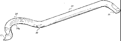
Fig. 1 is a perspective view of a tire chain tool
according to the present invention.
Fig. 2 is an environmental, perspective view of a
tire chain tool that shows the tool in an initial
3

CA 02496109 2008-05-14
installation position according to the present invention.
Fig. 3 is an environmental, perspective view of a
tire chain tool that shows the tool in an intermediate
installation position according to the present invention.
Fig. 4 is an environmental, perspective view of a
tire chain tool that shows the tool in a final
installation position according to the present invention.
Fig. 5 is an environmental, perspective view of a
tire chain tool that shows the tool in an initial
installation position.
25
3a

CA 02496109 2005-02-04
engaging the body of a chain link according to the present
invention.
Fig. 6 is an environmental, perspective view of the tool that
shows the tool insert in a cam-loc tightener according to the
present invention.
Similar reference characters denote corresponding features
consistently throughout the attached drawings.
DETAILED DESCRIPTION OF THE PREFERRED EMBODIMENT
The tire chain device is a one-piece, rugged tool made of
3/8" (1.0 cm) or 1/2" (1.3 cm) steel stock. In its preferred
embodiment, the tool has a total length of approximately 1 foot
(30 cm), but can be made longer or shorter dependent on a
prospective user's preference.
At a first end, the tool is provided with an open channel,
which open channel is capable of efficiently grabbing any
conventional quick chain hooks and levering the hook into
engagement with a chain link. The second end of the tool
terminates in an elliptical configuration that is dimensioned to
fit a conventional cam-loc structure, which cam-loc structure is
common to most truck tire chains. The second end can thereby be
utilized to tighten the cam-loc. The tool can be utilized to aid
in the mounting of chains on automotive vehicle tires. The tool
is of one-piece fabrication and has no moving parts. Easy to use,
the tool is fabricated from rugged material and will withstand
wear and tear.
Attention is first directed to Fig. 1 wherein the tool
comprises an elongate tubular body 10 fabricated from a rugged
material such as steel stock. The proximate end of body 10 is
defined by an arcuate portion 14. Portion 14 has an inside
surface 14a, which inside surface is beveled in order to reduce
the surface area in contact with the chain link. This design
4

CA 02496109 2005-02-04
decreases the amount of force required to lever the link to engage
the hook. Portion 14 terminates in a member 12, which member 12
is configured as an open-end channel. Portion 14 is positioned
immediately adjacent portion 12. A triangular-shaped protuberance
or nock 30 is positioned at the junction of body 10 and portion
14. Nock 30 prevents the chain link from sliding up the body 10
during the leveraging process and also provides a leveraging
point. The distal end of body 10 terminates in an L-shape, from
which extends an extruded elliptical member 16. Member 16 is
approximately one inch (2.5 cm) long and is sized to be received
in the opening of a conventional chain cam-loc device as will be
explained below. Member 16 is positioned in the same vertical
plane as portion 14.
Attention is now directed to Figs. 2-5 wherein the device is
illustrated in use. In Fig. 2 the device is shown in the initial
position wherein channel portion 12 is manipulated, by a user 4,
to grasp the end of a chain hook 20. Note that beveled surface
14a is disposed within chain link 22. Fig. 3 shows an
intermediate position wherein hook 20 is maneuvered in a position
to engage link 22. In a final position (Fig. 4), hook 20 is
levered into engagement with link 22. Fig. 5 shows an initial
position wherein the channel engages the body of a chain link.
Fig. 6 illustrates a scenario where member 16 is inserted in
a cam-loc device 24 to tighten the chain.
It is to be understood that the present invention is not
limited to the embodiment described above, but encompasses any and
all embodiments within the scope of the following claims.
5

Representative Drawing
A single figure which represents the drawing illustrating the invention.
Administrative Status

2024-08-01:As part of the Next Generation Patents (NGP) transition, the Canadian Patents Database (CPD) now contains a more detailed Event History, which replicates the Event Log of our new back-office solution.

Please note that "Inactive:" events refers to events no longer in use in our new back-office solution.

For a clearer understanding of the status of the application/patent presented on this page, the site Disclaimer , as well as the definitions for Patent , Event History , Maintenance Fee  and Payment History  should be consulted.

Event History

Description Date
Letter Sent 2024-02-05
Common Representative Appointed 2019-10-30
Maintenance Request Received 2017-01-11
Maintenance Request Received 2016-01-05
Maintenance Request Received 2014-12-18
Maintenance Request Received 2014-01-21
Maintenance Request Received 2013-01-11
Small Entity Declaration Request Received 2011-12-28
Small Entity Declaration Request Received 2011-01-04
Small Entity Declaration Determined Compliant 2010-01-08
Small Entity Declaration Request Received 2010-01-08
Grant by Issuance 2009-06-30
Inactive: Cover page published 2009-06-29
Small Entity Declaration Request Received 2009-03-27
Inactive: Final fee received 2009-03-27
Small Entity Declaration Determined Compliant 2009-03-27
Pre-grant 2009-03-27
Letter Sent 2008-11-04
Notice of Allowance is Issued 2008-11-04
Inactive: Approved for allowance (AFA) 2008-09-24
Amendment Received - Voluntary Amendment 2008-05-14
Inactive: S.30(2) Rules - Examiner requisition 2007-12-20
Application Published (Open to Public Inspection) 2005-11-12
Inactive: Cover page published 2005-11-11
Inactive: IPC assigned 2005-05-03
Inactive: First IPC assigned 2005-05-03
Inactive: Filing certificate - RFE (English) 2005-03-11
Letter Sent 2005-03-10
Application Received - Regular National 2005-03-10
All Requirements for Examination Determined Compliant 2005-02-04
Small Entity Declaration Determined Compliant 2005-02-04
Request for Examination Requirements Determined Compliant 2005-02-04

Abandonment History

There is no abandonment history.

Maintenance Fee

The last payment was received on 2009-01-05

Note : If the full payment has not been received on or before the date indicated, a further fee may be required which may be one of the following

  • the reinstatement fee;
  • the late payment fee; or
  • additional fee to reverse deemed expiry.

Patent fees are adjusted on the 1st of January every year. The amounts above are the current amounts if received by December 31 of the current year.
Please refer to the CIPO Patent Fees web page to see all current fee amounts.

Fee History

Fee Type Anniversary Year Due Date Paid Date
Application fee - small 2005-02-04
Request for examination - small 2005-02-04
MF (application, 2nd anniv.) - small 02 2007-02-05 2007-01-30
MF (application, 3rd anniv.) - small 03 2008-02-04 2008-01-21
MF (application, 4th anniv.) - small 04 2009-02-04 2009-01-05
Final fee - small 2009-03-27
MF (patent, 5th anniv.) - small 2010-02-04 2010-01-08
MF (patent, 6th anniv.) - small 2011-02-04 2011-01-04
MF (patent, 7th anniv.) - small 2012-02-06 2011-12-28
MF (patent, 8th anniv.) - small 2013-02-04 2013-01-11
MF (patent, 9th anniv.) - small 2014-02-04 2014-01-21
MF (patent, 10th anniv.) - small 2015-02-04 2014-12-18
MF (patent, 11th anniv.) - small 2016-02-04 2016-01-05
MF (patent, 12th anniv.) - small 2017-02-06 2017-01-11
MF (patent, 13th anniv.) - small 2018-02-05 2018-01-09
MF (patent, 14th anniv.) - small 2019-02-04 2019-02-04
MF (patent, 15th anniv.) - small 2020-02-04 2020-01-14
MF (patent, 16th anniv.) - small 2021-02-04 2021-01-29
MF (patent, 17th anniv.) - small 2022-02-04 2022-01-28
MF (patent, 18th anniv.) - small 2023-02-06 2023-01-27
Owners on Record

Note: Records showing the ownership history in alphabetical order.

Current Owners on Record
TIM WOODWORTH
DALE A. KINGMA
JOHN STOWERS
Past Owners on Record
None
Past Owners that do not appear in the "Owners on Record" listing will appear in other documentation within the application.
Documents

To view selected files, please enter reCAPTCHA code :


To view images, click a link in the Document Description column (Temporarily unavailable). To download the documents, select one or more checkboxes in the first column and then click the "Download Selected in PDF format (Zip Archive)" or the "Download Selected as Single PDF" button.

List of published and non-published patent-specific documents on the CPD .

If you have any difficulty accessing content, you can call the Client Service Centre at 1-866-997-1936 or send them an e-mail at CIPO Client Service Centre.

({010=All Documents, 020=As Filed, 030=As Open to Public Inspection, 040=At Issuance, 050=Examination, 060=Incoming Correspondence, 070=Miscellaneous, 080=Outgoing Correspondence, 090=Payment})


Document
Description 
Date
(yyyy-mm-dd) 
Number of pages   Size of Image (KB) 
Abstract 2005-02-03 1 15
Description 2005-02-03 5 217
Drawings 2005-02-03 6 136
Claims 2005-02-03 3 80
Representative drawing 2005-10-16 1 7
Claims 2008-05-13 2 64
Description 2008-05-13 6 215
Representative drawing 2009-06-03 1 7
Acknowledgement of Request for Examination 2005-03-09 1 178
Filing Certificate (English) 2005-03-10 1 158
Reminder of maintenance fee due 2006-10-04 1 110
Commissioner's Notice - Application Found Allowable 2008-11-03 1 164
Commissioner's Notice - Maintenance Fee for a Patent Not Paid 2024-03-17 1 551
Fees 2007-01-29 1 48
Fees 2008-01-20 1 56
Fees 2009-01-04 1 54
Correspondence 2009-03-26 1 57
Correspondence 2010-01-07 1 56
Fees 2010-01-07 1 56
Correspondence 2011-01-03 1 54
Fees 2011-01-03 1 57
Fees 2011-12-27 1 54
Correspondence 2011-12-27 1 53
Fees 2013-01-10 1 56
Fees 2014-01-20 1 43
Fees 2014-12-17 1 45
Maintenance fee payment 2016-01-04 1 43
Maintenance fee payment 2017-01-10 1 41
Maintenance fee payment 2018-01-08 1 24