Note: Descriptions are shown in the official language in which they were submitted.
CA 02496178 2005-02-18
WO 2004/025689 PCT/AU2003/001203
A MERCURY GAS DISCHARGE DEVICE
Field of the Invention
This invention relates to mercury gas discharge devices, in particular
mercury vapour fluorescent lamps including hot cathode and cold cathode
fluorescent lamps (CCFLs).
Background to the Invention
Nowadays, cold cathode fluorescent lamps (CCFLs) are often used as
miniature high luminous intensity light sources. They feature simple
construction, are miniature in size, have high luminous intensity, exhibit
small
increases in lamp temperature during operation, and have a relatively long
operating life. Because of these characteristics, CCFLs have been widely used
as a light source in various backlit light units and scanners.
In recent years, rapid developments in information technology,
communication equipment and office and consumer products have necessitated
development of CCFLs with better performance, increased functionality and
smaller size. Meanwhile, LCD backlit sources have been developed with the
aim of increasing the area of coverage, reducing power consumption and
extending operational lifetime. Currently, CCFLs are mass produced and have
great difficulty meeting these ever increasing demands.
An example of a current CCFL is shown in Figure 1. Figure 1 shows a
glass envelope 2 with a fluorescent powder film 4 coated onto its interior
wall.
Gas 5 such as a neon and argon mixture with a source of mercury vapour are
confined in glass envelope 2. Electrodes 1 are disposed at opposing ends of
glass envelope 2.
Electrodes 1 are a key component of the CCFL. They are responsible for
conducting electricity, emitting electrons, forming a magnetic field, and for
other
lamp and heating functions. To a large extent, lamp performance depends upon
the choice of the electrode material.
Electrodes commonly used in CCFLs include an electrode wire 6 formed
of tungsten, dumet or kovar and a cathode in the form of a nickel tube or
nickel
bucket 3 welded onto the part of electrode wire 6 which is inside glass
envelope
CA 02496178 2005-02-18
WO 2004/025689 PCT/AU2003/001203
2
2. Conventional nickel tubes or nickel buckets are made using high-ratio
compression.
In conventional CCFL construction, the operating surface area of the
nickel tube or nickel bucket 3 is limited by the inner diameter of glass
envelope
2 and the length of the electrode. Accordingly, any increase in the lamp's
luminous intensity during operation is limited by the surface area of the
nickel
tube or nickel bucket and the melting point of nickel which is approximately
1453°C. As a result of these limitations, current CCFL's are not able
to
withstand a large lamp electric current and the impact of a strong electron
stream. The limited surface area of the nickel tube or nickel bucket also
limits
the amount of active alkaline metals such as barium, calcium, strontium and
cesium that can be added. These metals can be added to the cathode to
enhance electron emission efficiency.
During long term operation, the glass and fluorescent powder used in
fluorescent lamps or current CCFLs continually discharge and deposit waste
materials inside the glass tube. Waste gases, such as water, oxygen, nitrogen,
carbon monoxide and carbon dioxide, develop and proliferate from the materials
used. These waste gases enter into the interior of the lamp. They result in an
increase in resistance to electrical conductivity within the lamp, and cause
damage to the cathode by reacting with the active alkaline metals that can be
added to the cathode. This reduces the functioning of the lamp and is known to
present difficulties when attempting to produce high quality, small sized,
high
luminous intensity and high performance fluorescent lamps and CCFLs.
The aforementioned problems do not only exist in CCFLs, but are also
found in any other mercury gas discharge device, including but not limited to
mercury vapour sunlamp and germ-killing ultraviolet light tube utilizing
mercury
vapour.
Summary of the Invention
It is an object of the present invention to provide a mercury gas
discharge device such as a cold cathode fluorescent lamp (CCFL) with a
construction that overcomes or at least ameliorates the problems of prior art
mercury gas discharge devices. Another object of the invention is to provide a
mercury gas discharge device such as a CCFL that operates under a larger
CA 02496178 2005-02-18
WO 2004/025689 PCT/AU2003/001203
3
operating electric current without affecting the device's operational
lifetime. It is
a further object of the present invention to provide a mercury gas discharge
device such as a CCFL that provides greater intensity and longer operational
lifetime when compared with current mercury gas discharge devices. These and
further objects and advantages of the present invention will be discussed in
more detail throughout the description of the invention.
A mercury gas discharge device constructed according to an
embodiment of the present invention comprises an envelope with inert gas and
mercury vapour confined within the envelope. The gas discharge device
includes a pair of electrodes which may be located inside or outside of the
envelope. One or more sintered metal portions are also located in the
envelope.
The sintered metal portions have high gettering characteristics with respect
to
waste gases, but low gettering characteristics with respect to the mercury
vapour.
Brief Description of the drawings
Figure 1 is a schematic diagram illustrating the construction of lenown
CCFLs.
Figure 2 is a schematic diagram illustrating a CCFL constructed in
accordance with an embodiment of the present invention.
Figure 3 is a graph showing the typical life span of a CCFL constructed in
accordance with an embodiment of the present invention.
Figure 4 is a schematic diagram illustrating a CCFL constructed in
accordance with another embodiment of the present invention.
Figure 5 is a schematic diagram illustrating a CCFL constructed in
accordance with a further embodiment of the present invention.
Figure 6 is a schematic diagram illustrating an external electrode
fluorescent lamp according to another embodiment of the invention.
Detailed Description of Preferred Embodiments
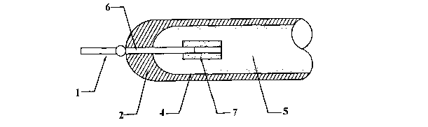
Referring firstly to Figure 2, there is provided a fluorescent lamp 10
comprising a tube 2 with an interior wall and an exterior wall and a
fluorescent
CA 02496178 2005-02-18
WO 2004/025689 PCT/AU2003/001203
4
powder film coating 4 on the interior wall. Inert gas and mercury vapour 5 are
confined within the tube and the lamp includes a pair of electrodes 1. One or
more sintered metal portions 11 are also located in tube 2. Sintered metal
portions 11 have high gettering characteristics with respect to waste gases
such
as water, oxygen, nitrogen, carbon monoxide and carbon dioxide, but low
gettering characteristics with respect to the mercury vapour.
One or more sintered metal portions 11 may be placed anywhere within
tube 2. It is preferred that sintered metal portions 11 are welded in the
tube,
preferably welded to one or more of electrodes 1, although welding to
electrodes is not essential. In an embodiment where one or more sintered metal
portions 11 are welded to an electrode, they may be welded to any part of the
electrode which is inside tube 2.
There may be any number of sintered metal portions 11 within tube 2.
The number of sintered metal portions 11 included is preferably determined by
the size of tube 2. When tube 2 is small, only one sintered metal portion 11
may
be required to achieve the advantages of the invention.
Now referring to Figures 4 and 5, schematic diagrams are shown which
illustrate two particular embodiments of the invention. In these embodiments,
tube 2 may be any appropriate type of tube and is preferably a glass tube. It
is
preferred that the sintered metal portion is a sintered metal tube (or bucket)
7 or
plate 8 (which can be in a pair as shown in Figure 5) which is welded on to
the
part of each electrode wire 6 which extends inside the tube. The sintered
metal
tube (or bucket) 7 or plate 8 may be manufactured using typical metal powder
metallurgy techniques or ultrasonic moulding press or any other appropriate
methodology.
During the sintering process, very small particles of the chemical element
are strongly bonded together under high temperature without melting the
elements. Bonding without melting results in a large number of internal pores
within the sintered article. These pores increase the physical gettering
characteristics of the metal portion by enhancing its porosity, and, when the
sintered portion is used as a cathode, increase the surface area for electron
emission and for adding active alkaline metals (such as barium, calcium,
strontium and cesium) for enhancing electron emission efficiency.
CA 02496178 2005-02-18
WO 2004/025689 PCT/AU2003/001203
The sintered metal tube 7 or plate 8 (which may also be provided in the
form of a bucket, not shown) preferably includes at least one metal element
which is selected from a first group of metal elements which have high
gettering
characteristics with respect to waste gases and low gettering characteristics
5 with respect to the mercury vapour within tube 2. Preferably such metal
elements have very low Bettering characteristics with respect to mercury
vapour. Accordingly the first group of metal elements includes but is not
limited
to ferrous family metals such as iron, nickel and cobalt. These metal elements
react chemically with waste gases such as water, oxygen, nitrogen, carbon
monoxide and carbon dioxide under operating temperatures of the lamp 10 but
not with the mercury vapour. Therefore, the Bettering characteristics of the
sintered metal tube 7 or plate 8 is enhanced by the inclusion of one or more
of
the metal elements included in the first group.
When the lamp 10 operates, high temperatures are generated inside
tube 2, particularly in the vicinity of electrode wires 6 (and sintered metal
tube 7
or plate 8 when used as a cathode or when welded to an electrode). As these
high temperatures develop, it is possible for sintered metal tube 7 or plate 8
to
break or sputter. Accordingly, it is preferred that sintered metal tube 7 or
plate 8
is a combination of metal elements which also includes one or more metals
from a second group that exhibit high temperature resistance in combination
with low or very low Bettering characteristics with respect to the mercury
vapour,
thereby reducing the possibility of sputtering. Metals such as molybdenum,
tungsten, tantalum and niobium are appropriate for inclusion in the second
group of metals.
Figure 6 illustrates a further arrangement in which the electrodes 12 are
entirely outside of tube 2. This type of arrangement is known as an external
electrode fluorescent lamp (EEFL). In this particular arrangement, each end of
tube 2 is capped with an electrode 12, each of which has an electrical
connector
13. As is the case with each of the other embodiments, tube 2 has a powder
film coating 4 on the interior wall, and inert gas and mercury vapour 5 are
confined within the tube 2. One or more sintered metal portions may be located
anywhere within the tube. In the particular arrangement illustrated, a
sintered
metal portion in the form of sintered tube 7 is located at one end of the EEFL
tube 2, held in place by a neck portion of EEFL tube 2.
CA 02496178 2005-02-18
WO 2004/025689 PCT/AU2003/001203
6
In a preferred embodiment, sintered metal tube 7 or plate 8 is a metallic
combination comprising between 2 and 5 metal elements with at least one of
the metal elements being selected from the first group (high gettering
characteristics with respect to waste gases but not mercury vapour) and at
least
one of the metal elements being selected from the second group (resistant to
high temperatures with low or very low gettering characteristics with respect
to
mercury vapour). It is preferred that the sintered metallic combination is
porous
with a porosity of 50% to 4% and a relative density of 50% to 96%.
In another embodiment, where the sintered metal portion is used as a
cathode, the metal portion further includes one or more active alkaline metals
for enhancing the efficiency with which electrons are emitted from the
cathode.
The active alkaline metals may include but are not limited to barium, calcium,
strontium, and cesium.
Referring to Figure 3, a graph shows brightness or luminous intensity
versus life span for a CCFL constructed with a sintered porous metal tube or
plate according to the present invention. In the primary stage of operation
(i.e.
during approximately the.first 200 hours of operation), the graph of Figure 3
shows a distinct drop in luminous intensity of around 3 to 5%. This is due to
the
proliferation of waste gases derived from the glass, fluorescent powder and
the
electrodes. The proliferation of these waste gases results in contamination
and
sputtering inside the lamp. Meanwhile, during operation the sintered porous
metal tube or plate continues to attempt to increase absorption of the waste
gases.
After around 400 hours of operation, the proliferation of waste gases
stabilizes and the sintered metal tube or plate begins to function as a
gettering
device, absorbing large quantities of the waste gases. As the waste gas
content
in the glass tube decreases, the luminous intensity of the lamp increases, and
the CCFL regains its former luminosity as evidenced by the rapid increase in
luminous intensity in Figure 3. This advantage can not be achieved by
conventional mercury vapour fluorescent lamps.
During aging, luminosity drops due to the generation of the waste gases.
Mercury vapour is also slowly and gradually absorbed by the fluorescent
powder contributing further to the drop in luminosity, but such drop is of a
lesser
extent because the chemical affinity between fluorescent powder and mercury
CA 02496178 2005-02-18
WO 2004/025689 PCT/AU2003/001203
7
vapour is weak. Figure 3 shows a gradual linear decline in luminosity or
brightness which corresponds to this aging process. However, the decrease in
luminous intensity is slower and steadier than that of conventional CCFLs.
Since the decrease occurs over a longer time, the aging period of the lamp of
the present invention is much longer than that of conventional lamps. After
approximately 15000 hours of operation, the fall in luminous intensity of a
fluorescent lamp constructed according to the present invention is around 10%
less than the fall in brightness which occurs in conventional fluorescent
lamps
after the same lifetime. This is achieved in part by the continuous gettering
function provided by the sintered metal portion which maintains a very low
level
of waste gases in the glass tube during lamp operation.
This is complemented by the fact that the sintered metal selected does
not react with or absorb mercury vapour during operation. As a result, the
content of the mercury vapour within the tube is maintained at a higher level
for
longer, thereby reducing the rate at which the lamp's luminous intensity
decreases when compared with conventional lamps.
According to the luminous intensity vs lifespan graph of Figure 3, it is
anticipated that the fluorescent lamp of the present invention is capable of
withstanding twice the operational electric current of conventional
fluorescent
lamps. For example, the operational electric current of a conventional CCFL
with an outer diameter of 2.6mm is 5mA. However, a CCFL constructed in
accordance with the present invention with the same outer diameter and with a
sintered porous metallic combination tube can withstand an operational
electric
current of up to 10mA, achieving an increased luminous intensity of 3,000 to
10,OOOcd/m2 whilst maintaining comparable lamp life (approximately 15,000 to
20,000 hours). Further, if the CCFL of the present invention and the
conventional CCFL operate using the same current, the operational life of the
inventive CCFL may exceed 50,000 hours. This is an improvement of 100 to
150% when compared with conventional CCFLs.
Figure 4 shows a schematic illustration of a CCFL constructed according
to an embodiment of the present invention. It comprises glass envelope 2,
fluorescent powder film 4 coated onto the interior wall of glass envelope 2
and
inert gas and mercury vapour 5 confined inside glass envelope 2. Electrodes 1
are located at the ends of the lamp (only one shown). Electrodes 1 include
CA 02496178 2005-02-18
WO 2004/025689 PCT/AU2003/001203
electrode wire 6 sealed at the end of envelope 2 and extending from the
interior
to the exterior of envelope 2. In contrast to the CCFL of Figure 1, the
inventive
CCFL has a sintered metal tube 7 composed of a combination of 2 to 5 metal
elements welded onto electrode wires 6 and used as a cathode, although
sintered metal tube 7 may be welded anywhere in glass envelope 2. This
replaces the conventional nickel tube 3 illustrated in Figure 1.
The inventive sintered metal tube 7 is produced by metallic powder
processes using typical powder metallurgy and is, therefore, a porous product.
As a result, its surface area is 2 to 20 times greater than that of the high
density
compacted nickel tube of conventional lamps. The sintered metal tube 7 can
therefore absorb or accommodate more of active alkaline metals such as
barium, calcium, strontium and cesium etc. which act as activating elements
for
electron emission, thereby reducing the resistance to electron emission at
cathode.
The inventive sintered metal portion composition is preferably chosen
from the following group of compositions:
CA 02496178 2005-02-18
WO 2004/025689 PCT/AU2003/001203
9
iron or nickel or cobalt OR
1. tungsten or molybdenum70l0 10% iron + nickel +
cobalt OR
or tantalum or niobiumto TO to iron +nickel OR
OR 90% 30% iron + cobalt OR
tungsten + molybdenum nickel + cobalt
OR
tungsten + niobium
OR
tungsten + tantalum
OR
molybdenum + niobium
OR
molybdenum + tantalum
OR
tantalum + niobium
OR
tungsten + molybdenum +
tantalum + niobium
OR
tungsten + molybdenum +
tantalum
OR
tungsten + molybdenum +
niobium
' OR
tungsten + tantalum +
niobium
OR
molybdenum + tantalum +
niobium
iron or nickel or cobalt OR
2. tungsten or molybdenum 40% 30% iron + nickel OR
or tantalum or niobiu to TO to iron + cobalt OR
OR 70% 60% nickel + cobalt OR
tungsten + molybdenum iron + nickel +cobalt
OR
CA 02496178 2005-02-18
WO 2004/025689 PCT/AU2003/001203
tungsten + niobium
OR
tungsten + tantalum
OR
molybdenum + niobium
OR
molybdenum + tantalum
OR
tantalum + niobium
OR
tungsten + molybdenum +
tantalum + niobium
OR
tungsten + molybdenum +
tantalum ,
OR
tungsten + molybdenum +
niobium
OR
tungsten + tantalum +
niobium
OR
molybdenum + tantalum +
niobium
iron or nickel or cobalt OR
3. tungsten or molybdenum10% 60% iron + nickel OR
or tantalum or niobium iron + cobalt OR
to TO to
OR 40% 90% nickel + cobalt
OR
tungsten + molybdenum iron + nickel +cobalt
OR
tungsten + niobium
OR
tungsten + tantalum
OR
molybdenum + niobium
CA 02496178 2005-02-18
WO 2004/025689 - PCT/AU2003/001203
11
OR
molybdenum + tantalum
OR
tantalum + niobium
OR
tungsten + molybdenum +
tantalum + niobium
OR
tungsten + molybdenum +
tantalum
OR
tungsten + molybdenum +
niobium
OR
tungsten + tantalum +
niobium
OR
molybdenum + tantalum +
niobium
It is not necessary for the inventive sintered metal portion to be composed
only
of elements in the aforementioned first and second groups of metal elements.
However, it is preferred that the proportion of metal elements selected from
the
first group in combination with the proportion of metal elements selected from
the second group comprises between 50% and 100% of the total sintered metal
composition.
CAS E STU DY 1
A linear CCFL is produced with an outer diameter of 2.6mm, an inner
diameter of 2.Omm, a lamp length of 243mm and uses a sintered porous metal
tube composed of tungsten, molybdenum, iron and cobalt and welded onto a
tungsten electrode. The composition is:
tungsten + molybdenum: 10 to 40%
iron + cobalt: 90 to 60%
The electrode tube is sealed in a borosilicate (hard glass) tube, the
interior wall of which is coated with fluorescent powder film with a color
CA 02496178 2005-02-18
WO 2004/025689 PCT/AU2003/001203
12
temperature of 5800°K. The borosilicate tube is filled with an
appropriate
neon/argon gas combination and a mercury vapour source, and is ignited with
circuitry known in the art. In operation at 7.5mA and 15mA, the CCFL of Case
Study 1 has performance characteristics as shown in Table 1 below.
Operating Current7.5mA 15mA Performance Change
Luminous Intensity44000cd/m 55000 cd/m +25%
Luminous Flux 176 lumen 212 lumen +20.5%
After intensive aging test, equivalent to 4,000 hours of normal operation:
Luminous Intensity42030 cd/m' 52030 cd/m +23.8%
Luminous Flux 151 lumen 189 lumen +25%
Decrease in Luminous4.5% ~ 5.4%
Intensity Conventional
average
drop is
8.5-10%
Table 1
Extrapolating the data obtained from Case Study 1, it is estimated that a
CCFL constructed using the described porous sintered metal combination will
achieve a lamp life of 25,000 to 30,000 hours of continuous operation at
7.5mA,
and a lamp life of 10,000 to 15,000 hours of continuous operation at 15mA.
This
performance exceeds the capabilities of conventional CCFLs.
CASE STUDY 2
A linear cold cathode fluorescent lamp (CCFL) is produced with an outer
diameter of 1.8mm, an inner diameter of 1.2mm and lamp length of 72.5mm as
illustrated in Figure 5. The feature distinguishing the CCFL of Figure 5 from
that
of Figure 4 is the use of porous sintered metal plate 8 in place of tube 7.
The
sintered porous metal plate is composed of tungsten, molybdenum, iron, nickel
and cobalt and is welded onto a tungsten electrode. The composition is:
tungsten + molybdenum: 10 to 40%
iron + nickel + cobalt: 90 to 60%
The electrode plate is sealed in a borosilicate (hard glass) tube, the
interior wall of which is coated with fluorescent powder film with a color
temperature of 6500°K. The borosilicate tube is filled with an
appropriate
CA 02496178 2005-02-18
WO 2004/025689 PCT/AU2003/001203
13
neon/argon gas combination and a mercury vapour source, and is ignited with
circuitry, as known in the art. In operation at 2mA and 3mA, the CCFL of Case
Study 2 has performance characteristics as shown in Table 2 below.
Operating Current2mA 3mA Performance Change
Luminous Intensity28930 cd m 40070 cd/m +38.5%
After intensive aging test, equivalent to 6,250 hours of normal operation:
Luminous Intensity26520 cd/m' 34150 cd/m' +28.7%
Decrease in 8.3% 14.8% -
Luminous Intensity
Table 2
It is to be noted that conventional lamps are not capable of operating for
extended periods at an operational current of 2mA.
CASE STUDY 3
A linear cold cathode fluorescent lamp (CCFL) is produced with an outer
diameter of 2.6mm, an inner diameter of 2.Omm and a lamp length of 243mm. It
uses a sintered porous metal tube composed of tungsten, molybdenum, iron
and cobalt and welded onto a tungsten electrode. The composition is:
tungsten + molybdenum: 70 to 90%
iron + cobalt: 30 to 10%
The electrode tube is sealed in a borosilicate (hard glass) tube, the
interior wall of which is coated with fluorescent powder film with a color
temperature of 5800°K. The borosilicate tube is filled with an
appropriate
neon/argon gas combination and a mercury vapour source, and is ignited with
circuitry, as known in the art. In operation at 7.5mA, the CCFL of Case Study
3
has performance characteristics as shown in Table 3 below.
Operating Current 7.5mA
Luminous Intensity 44000 cd/m'
After intensive aging test, equivalent to 15,000 hours of normal operation:
CA 02496178 2005-02-18
WO 2004/025689 PCT/AU2003/001203
14
Luminous Intensity 39020 cd~m
Decrease in Luminous 11.3%
Intensity
(conventional average
drop: 29%)
Table 3
Extrapolating the data obtained from Case Study 3, it is estimated that a
CCFL constructed using the described porous sintered metal tube will achieve a
life of approximately 40,000 hours of continuous operation.
CASE STUDY 4
A linear CCFL is produced with an outer diameter of 4.Omm, an inner
diameter of 2.9mm, a lamp length of 264mm and uses a sintered porous metal
tube composed of niobium, molybdenum, iron, nickel and cobalt and welded
onto a tungsten electrode. The composition is:
niobium + molybdenum: 30%
iron + nickel + cobalt: 70%
The electrode tube is sealed in a borosilicate (hard glass) tube, the
interior wall of which is coated with fluorescent powder film with a color
temperature of 5200°K. The borosilicate tube is filled with an
appropriate
neon/argon gas combination and a mercury vapour source, and is ignited with
circuitry known in the art. In operation at 8.2mA and 6.4mA, the CCFL of Case
Study 4 has performance characteristics as shown in Table 4 below.
Operating Current8.2mA 16.4mA Performance Change
Luminous Intensity26900cd/m' 42800 cd/m' +59%
Luminous Flux 176 lumen 248 lumen +40.9%
After intensive aging test, equivalent to 15,000 hours of normal operation:
Luminous Intensity23700 cd/m 36670 cd/m +49.0%
Luminous Flux 156 lumen 218 lumen +39.7%
Decrease in Luminous11.9% 14.3%
Intensity
Decrease in Luminous11.4% 12.1
Flux
CA 02496178 2005-02-18
WO 2004/025689 PCT/AU2003/001203
Table 4
Extrapolating the data obtained from Case Study 4, it is estimated that a
CCFL constructed using the described porous sintered metal combination will
5 achieve a lamp life of 50,000 or more hours of continuous operation at
8.2mA,
and a lamp life of 10,000 to 15,000 hours of continuous operation at 16.4mA.
This performance exceeds the capabilities of conventional CCFLs.
CASE STUDY 5
10 A linear CCFL is produced with an outer diameter of l.8mm, an inner
diameter of 1.4mm, a lamp length of 38.5mm and uses a sintered porous metal
tube composed of tungsten, tantalum, iron and cobalt and welded onto a
tungsten electrode. The composition is:
tungsten + tantalum: 80%
15 iron + cobalt: 20%
The electrode tube is sealed in a borosilicate (hard glass) tube, the
interior wall of which is coated with fluorescent powder film with a color
temperature of 12000°K. The borosilicate tube is filled with an
appropriate
neon/argon gas combination and a mercury vapour source, and is ignited with
circuitry known in the art. In operation at 3mA and 6mA, the CCFL of Case
Study 5 has performance characteristics as shown in Table 5 below.
Operating Current3mA 6mA Performance Change
Luminous Intensity30600cd/m' 45000 cd/m' +47.1
Luminous Flux 10 lumen 13.5 lumen +35%
After intensive aging test, equivalent to 4,000 hours of normal operation:
Luminous Intensity27600 cd/m 37710 cd/m
Luminous Flux 8.5 lumen 11 lumen
Decrease in Luminous9.6! 16.2%
Intensity
Decrease in Luminous15% 18.5%
Flux
Table 5
CA 02496178 2005-02-18
WO 2004/025689 PCT/AU2003/001203
16
Extrapolating the data obtained from Case Study 5, it is estimated that a
CCFL constructed using the described porous sintered metal combination will
achieve a lamp life of about 50,000 hours of continuous operation at 3mA.
The mercury gas discharge device (such as a CCFL) constructed
according to the present invention uses sintered metal portions (such as
tubes,
buckets or plates) to improve gettering with respect to waste gases within the
device envelope, thus increasing intensity, extending lifetime of the device
and
significantly improving performance. In one embodiment, the inventive sintered
metal portion is porous. Therefore, it has an increased operational surface
area
when compared with the getters of conventional mercury gas discharge devices
or CCFLs. Accordingly, the device is able to withstand higher operating
currents
whilst maintaining steady operating conditions and intensity; when the
operating
current increases, so too does the intensity or luminous intensity. In
particular, a
CCFL with a porous sintered portion, when used as the cathode and
constructed according to an embodiment of the present invention, exhibits a
significantly higher luminous intensity index than conventional fluorescent
lamps.
It is to be noted that a mercury gas discharge device (such as a CCFL)
constructed according to an embodiment of the present invention would also
exhibit an increase in temperature during operation. The increase in
temperature will release any mercury vapour which has become physically
trapped within the sintered metal portion, but will not release waste gases as
they will be chemically bound to the "gettering" metal.
A sintered metal portion according to an embodiment of the present
invention forms compounds with waste gases in the device envelope and
absorbs them. These sintered metal portions become more active when
protected in a vacuum or inert gas environment. Accordingly, they exhibit .a
stronger binding force to waste gases such as oxygen, nitrogen, carbon
monoxide and carbon dioxide as well as water, thereby providing significantly
improved gettering characteristics as well as serving as "conventional"
cathode
when welded to the end of an electrode inside the device envelope.
CA 02496178 2005-02-18
WO 2004/025689 PCT/AU2003/001203
17
The inventive sintered metal portion is ideal for use in multi-functional,
high efficiency and long life CCFLs. A CCFL according to the present invention
exhibits a life span which is among the longest of all CCFLs.
Although the present invention has been described in relation to
particular embodiments thereof, many other variations and modifications and
other uses will become apparent to those skilled in the art. It is preferred,
therefore, that the present invention be limited not by the specific
disclosure
herein, but only by the appended claims.