Note: Descriptions are shown in the official language in which they were submitted.
CA 02496882 2005-02-24
WO 2004/022142 PCT/US2003/027587
METERING VALVE FOR A METERED DOSE INHALER
PROVIDING CONSISTENT DELIVERY
Background
Metering valves are a common means by which aerosols are dispensed from
aerosol containers. Metering valves are particularly useful for administering
medicinal
formulations that include a liquefied gas propellant and are delivered to a
patient in an
aerosol.
When administering medicinal formulations, a dose of formulation sufficient to
produce the desired physiological response is delivered to the patient. The
proper
predetermined amount of the formulation must be dispensed to the patient in
each
successive dose. Thus, any dispensing system must be able to dispense doses of
the
medicinal formulation accurately and reliably to help assure the safety and
efficacy of the
treatment.
Metering valves have been developed to provide control over the dispensing of
medicinal aerosol formulations. A metering valve may be used to regulate the
volume of a
medicinal formulation passing from a container to a metering chamber, which
defines the
maximum amount of the formulation that will be dispensed as the next dose.
Reliable and
controllable flow of the medicinal formulation into the metering chamber may
contribute
to the accuracy and/or precision of the metering of successive doses of the
formulation.
Thus, reliable and controllable flow of the medicinal formulation into the
metering
chamber may improve performance of the metering valve and, therefore, may be
highly
desirable.
In some metering valves, the metering chamber fills with the medicinal
formulation
prior to the patient actuating the valve stem and thereby releasing the dose.
The metering
chamber is refilled with formulation after dispensing one dose so that the
metering valve is
ready to discharge the next dose. Consequently, the metering chamber contains
formulation at all times except for the brief time during which the valve stem
is depressed
by the user to discharge a dose. Also, the passageways through which the
formulation
must flow to reach the metering chamber are often narrow and tortuous. As a
result,
metering valves configured in this way have a number of disadvantages
resulting in, for
1
CA 02496882 2005-02-24
WO 2004/022142 PCT/US2003/027587
example, erratic dosing due to loss of prime. "Loss of prime" means the
occurrence of
vapor or air voids in the metered volume, thereby leading to a shortfall in
the volume of
dose being metered by the valve. A principal cause of loss of prime is the
presence of
restrictions in the entry passageway or passageways through which formulation
must pass
to fill the metering chamber. Such restrictions can lead to flow disruption
and thus also to
the occurrence of vapor or air voids in the metering chamber.
Another phenomenon that can lead to erratic dosing is loss of dose. "Loss of
dose"
means a change in the amount of suspended drug or excipient particles in a
metered dose
of formulation, compared to the average composition of the bulk formulation in
the
container. A principal cause of loss of dose is the settling of drug particles
into, or their
movement out of, restricted regions of the metering valve such that the proper
concentration of formulation cannot subsequently be obtained within the
restricted regions
prior to dose delivery. For example, drug particles may settle in a residual
metering
volume - any part of the metering valve bounded by a metering surface and
that, when the
metering valve is in the resting position, remains fluid filled but is not in
substantially free-
flowing communication with the bulk formulation.
In other metering valves, residual metering volume may be limited to some
extent
by designing the metering valve so that the metering chamber does not
materialize unless
and until the valve stem is actuated. However, even in these metering valves,
a small
residual metering volume exists when the metering valve is at rest because a
small annular
gap exists between the valve stem and the metering valve body.
Actuation of these valve stems can be divided into a filling stage and a
discharge
stage. The filling stage begins as the valve stem is depressed during
actuation. The action
of depressing the valve stem causes the formation of a transient metering
chamber, which
is in fluid communication with the residual metering volume defined by the
small annular
gap. As the valve stem is depressed, the transient portion of the metering
chamber
expands and formulation enters the metering chamber. As displacement of the
valve stem
continues, a stage is reached at which filling of the transient metering
chamber stops.
Eventually, displacement of the valve stem continues to the discharge stage,
in
which the metered formulation is discharged. In these valves, a single
actuation thus
causes rapid filling of the transient metering chamber followed by discharge
of the
2
CA 02496882 2005-02-24
WO 2004/022142 PCT/US2003/027587
formulation to the patient. Generally, metered formulation does not reside for
any
appreciable length of time in the metering chamber in these metering valves.
However,
some formulation may reside in the residual metering volume defined by the
small annular
gap when the metering valve is at rest.
Some metering valves limit the height of the annular gap, thereby reducing the
residual volume and limiting the amount of formulation that resides in the
metering
chamber between actuation events.
While a metering valve having a transient metering chamber provides advantages
over other types of metering valves for the delivery of aerosol formulations,
the flow of
formulation from the container to the metering chamber may be disrupted.
Disrupted flow
of formulation refers to filling a metering chamber through one or more
bottleneck regions
of significantly restricted access. Flow through the bottleneck regions may be
impeded
sufficiently to give rise to substantially incomplete filling of the metering
chamber,
particularly under conditions typical of patient use. When this happens,
formulation may
be delivered in inconsistent or inaccurate doses. Of course, all metering
chamber inlets
become significantly restricted immediately prior to being sealed off during
actuation.
Disrupted flow, as just described, refers to flow access during the majority
of the filling
stage of actuation.
Certain metering valves have been designed to improve the now of formulation
into the metering chamber. For example, some metering valves include angled
spillway
filling channels designed to limit disruption of the flow of formulation into
the metering
chamber. Less disrupted flow may decrease the likelihood and extent to which
vapor or
air voids form in the metered volume and, therefore improve performance of the
metering
valve.
Summary of the Invention
The present invention relates to a novel design for a metering valve that
provides
improved consistency of formulation delivery. The metering valve of the
present
invention includes a valve stem designed to (1) limit or eliminate the
residual metering
volume, thereby reducing the amount of formulation that resides in the
metering chamber
while the metering valve is at rest, and (2) limit restrictions on the free
flow of formulation
3
CA 02496882 2010-07-22
into the metering chamber. Consequently, consistent delivery of formulation is
obtained
by reducing the effects of loss of prime and loss of dose.
The present invention provides an aerosol metering valve that includes a valve
stem that generally defines a longitudinal axis, a valve body, and a metering
gasket
configured to be able to form a transient, substantially fluid-tight face seal
between the
valve stem and a sealing portion of the valve body. The valve stem includes a
body
portion including a proximal end, a distal end, and at least one side surface
connecting the
proximal end and the distal end and including a metering surface, wherein the
longitudinal
axis and a plane tangential to at least a portion of the metering surface
define an angle
from about 2 to about 90 .
More specifically, the invention as claimed provides an aerosol metering
valve comprising:
(a) a valve stem that generally defines a longitudinal axis and comprises:
(1) a body portion comprising a proximal end, a distal end, and at
least one side surface connecting the proximal end and the distal end and
comprising a metering surface, wherein the longitudinal axis and a plane
tangential
to at least a portion of the metering surface define an angle from about 2 to
about
90 , and
(2) a stem portion comprising a discharge passageway;
(b) a valve body comprising:
(1) a body wall that comprises a sealing portion,
(2) an internal chamber defined at least in part by the body wall and
comprising a metering portion configured to substantially conform to the
metering
surface of the valve stem, and
(3) a diaphragm having walls that define an aperture in slidable,
sealing engagement with the stem portion of the valve stem; and
(c) a metering gasket configured to be able to form a transient, substantially
fluid-tight face seal between the valve stem and the sealing portion of the
body wall.
4
CA 02496882 2010-07-22
Brief Description of the Drawings
FIG. 1 is a cross-sectional view of a metered dose inhaler including an
embodiment
of the aerosol metering valve according to the present invention.
FIG. 2 is an enlarged cross-sectional view of one embodiment of another
aerosol
metering valve according to the present invention in the resting position.
FIG. 3 is an enlarged cross-sectional view of the aerosol metering valve shown
in
FIG. 2 during the filling stage of valve stem actuation.
FIG. 4 is an enlarged cross-sectional view of the aerosol metering valve shown
in
FIG. 2 at the filled stage of valve stem actuation.
FIG. 5 is an enlarged cross-sectional view of the aerosol metering valve shown
in
FIG. 2 during the discharge stage of valve stem actuation.
FIGS. 6 and 7 are enlarged cross-sectional views of the embodiment of an
aerosol
metering valve shown in Figure 1 in the resting position and during the
discharge stage of
the valve stem actuation, respectively.
FIGS. 8 and 9 are enlarged cross-sectional views of a further embodiment of an
aerosol metering valve according to the present invention in the resting
position and during
the discharge stage of the valve stem actuation.
FIG. 10 is an enlarged cross-sectional view of one embodiment of a valve stem
according to the present invention.
4a
CA 02496882 2005-02-24
WO 2004/022142 PCT/US2003/027587
FIG. 11 is an enlarged cross-sectional view of an alternative embodiment of a
valve
stem according to the present invention.
FIG. 12 is an enlarged cross-sectional view of another alternative embodiment
of a
valve stem according to the present invention.
Detailed Description of the Invention
The following description is set forth in terms of an aerosol metering valve
used to
dispense an aerosol formulation from an aerosol container. However, the
metering valve
and methods of the present invention have application to virtually any
pressurized fluid
requiring delivery of an accurate, metered dose. In particular, the metering
valves
described herein are useful for dispensing medicinal aerosol formulations.
When used to dispense medicinal aerosol formulations, a metering valve
according
to the present invention may be used to administer virtually any aerosol
formulation of
drug into a body cavity of a patient, such as the mouth, nose, anus, vagina,
ears, or onto the
eyes or any skin area of the patient. However, the present invention is not
limited to
medicinal applications and may be used wherever a precise amount of material
from a
pressurized fluid is to be delivered to a given region.
FIG. 1 shows an aerosol dispensing apparatus, generally designated as 10, that
incorporates one embodiment of a metering valve 14 according to the present
invention.
The top end of the metering valve 14 is crimped around the end of a
conventional aerosol
container 12, while a conventional discharge piece 16 is mounted around the
bottom of the
metering valve 14. Thus, aerosol formulation is dispensed downwardly from the
aerosol
container 12, through the metering valve 14, then through the discharge piece
16 where it
is delivered to a patient. The discharge piece 16 directs the aerosol
formulation toward the
body cavity or skin area to which the formulation is to be delivered. For
example,
discharge piece 16 may be a mouthpiece that can be inserted into the patient's
mouth,
thereby providing oral administration of the aerosol formulation.
The aerosol-dispensing device shown in FIG. 1 is merely one example of how a
metering valve according to the present invention can be incorporated into a
dispensing
apparatus. Furthermore, the configuration of the discharge piece 16 depends
upon the
application for the aerosol.
5
CA 02496882 2005-02-24
WO 2004/022142 PCT/US2003/027587
In many of the figures, a metering valve or valve stem is shown in isolation
for
ease of illustration. The valve stems shown in isolation may be combined with
one or
more additional components to form a metering valve. Such metering valves, as
well as
metering valves shown in isolation in the figures, may be combined with one or
more
additional components to form an aerosol dispensing device. It is understood
that any
particular feature shown in a metering valve and/or valve stem embodiment may
be
combined with features shown in other embodiments and/or incorporated
appropriately
within other embodiments.
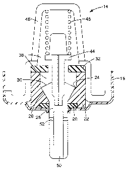
Referring to FIG. 2 showing an embodiment of a metering valve 14 (in the
resting
position), the metering valve 14 typically includes a housing 18 that serves
to house the
various components of the metering valve 14. The top portion of the housing 18
attaches
to the aerosol container 12 (as exemplarily shown in FIG. 1). A valve body 22,
typically
seated within the valve housing 18, in turn provides a housing for a valve
stem 26. The
valve body 22 includes an interior surface 24 defining an internal chamber or
cavity of the
valve body.
The metering valve 14 typically includes a spring cage 46 that, together with
the
valve body 22, defines an interior chamber 38, a portion of which is occupied
by a portion
of the valve stem 26. One or more inlets (not shown) typically traversing the
spring cage
provide open and unrestricted fluid communication between the interior chamber
38 and
the aerosol container 12.
The valve stem 26 includes two portions, a body portion and a stem portion.
The
stem portion includes that portion of the valve stem that is outside the valve
housing 18
when the valve stem 26 is in the resting position shown in FIG. 2. During
actuation of the
valve stem 26, however, the stem portion will be displaced inwardly with
respect to the
metering valve 14, as described more fully below, so that some of the stem
portion will be
transiently positioned inside the valve housing 18. The stem portion includes
a
passageway 50 through which a metered dose of formulation is discharged, as
will be
described more fully below. The passageway includes one or more side holes 52.
The body portion of the valve stem 26 is that portion that is positioned
within the
valve housing 18 throughout actuation of the valve stem 26. The body portion
of the valve
stem 26 (as shown in FIGS. 2-5) includes a metering surface 28 and a sealing
surface 30.
6
CA 02496882 2005-02-24
WO 2004/022142 PCT/US2003/027587
The body portion of the valve stem 26 is configured to have substantially the
same
shape as the surrounding wall of the valve body 22. 'Thus, as can be seen in
the
embodiment shown in FIG. 2, a substantial portion of the metering surface 28
of valve
stem 26 rests in contact with the interior surface of the valve body 24 when
the metering
valve is in the resting position, thereby minimizing, if not eliminating, the
annular gap
between the valve stem and valve body when the metering valve is in the
resting position,
and thus minimizing, if not eliminating, residual metering volume.
The metering valve may include a spring guide 44 mounted on the end of the
valve
stem body portion opposite the stem portion and a spring 48 within the
interior chamber 38
of the metering valve as shown in FIG. 2. The spring 48 through engagement
with the
spring guide biases the valve stem 26 toward the resting position. It will be
appreciated by
those skilled in the art that any suitable means for biasing the valve stem 26
into the
resting position, e.g. coil compression spring or a spring appropriately
mounted external to
the interior chamber, may be used in connection with metering valves according
to the
present invention. The spring guide may be an integral part of the valve stem
and/or
arranged to include a pressure filling ring as described in the US Patent US
5,400,920,
which is incorporated by reference herein.
The metering valve 14 also includes at least two annular gaskets, the
diaphragm 20
and the metering gasket 32. The diaphragm 20 is positioned between the valve
housing
18, the valve body 22 and the valve stem 26, as shown in FIG. 2. The diaphragm
20
isolates the formulation in the aerosol container 12 from the exterior of the
valve by
forming two fluid tight seals: 1) an annular sliding seal between the
diaphragm 20 and the
valve stem 26 where the valve stem extends out of the valve housing, and 2)
two
compressive planar or face seals between the valve body 22, the diaphragm 20
and the
housing 18. The latter seal may be effected either with or without a sealing
bead on either
the valve body 22 or the housing 18.
In the embodiment shown in FIGS. 2-5, the metering gasket 32 is included in
the
body wall of the valve body, being generally positioned between the valve body
22, the
spring cage 46, and the body portion of the valve stem 26. The metering gasket
32 forms
two fluid tight compressive planar or face seals between the metering gasket
32 and the
7
CA 02496882 2005-02-24
WO 2004/022142 PCT/US2003/027587
valve body 22 and the spring cage 46. These may be achieved either with or
without a
sealing bead on the valve body 22 and/or the spring cage 46.
The metering gasket in this embodiment or other embodiments in accordance with
the present invention may be either mechanically affixed, molded onto the
respective
component of the metering valve, or the respective components may be
manufactured
using, for example, a two shot or co-molding process in which the
corresponding
component of the metering valve and metering gasket are co-molded so that a
strong bond
(mechanical and/or chemical) can be achieved between the components.
As shown in FIG. 4, the metering gasket 32 transiently isolates the
formulation in
the metering chamber 34 from the aerosol container 12 by forming a fluid-tight
face seal
between the metering gasket 32 and the sealing surface 30 of the valve stem
26. The
metering gasket 32 provides a means for terminating the flow of formulation
from the
aerosol container 12 to the metering chamber 34 during actuation of the valve
stem 26, as
will be described in more detail below.
Operation of the metering valve 14 shown in FIG. 2 is illustrated in FIGS. 3,
4 and
5. The figures illustrate the stages of operation of the metering valve 14 and
the
corresponding relative positions of the valve components as a patient actuates
the valve
stem 26, thereby releasing a dose of aerosol formulation. FIG. 3 shows the
metering valve
14 in the filling stage, FIG. 4 shows the metering valve 14 in the filled
stage, and FIG. 5
shows the metering valve 14 in the discharge stage.
As can be seen in FIG. 3 during the filling stage of actuation, the valve stem
26 has
been displaced inwardly into the interior chamber 38 against the compressive
force of the
spring 48. As the valve stem 26 is displaced inwardly, the proximal end of the
stem
portion of the valve stem 26 enters the valve housing 18. As a result, a
metering chamber
34 is formed between the interior surface of the valve body 24 and the
metering surface 28
of the valve stem 26. The volume of the metering chamber 34 increases as the
valve stem
is displaced until it reaches its filled-volume at the end of the filling
stage as depicted in
FIG. 4 showing the completely filled position.
Aerosol formulation enters the filling volume of the metering chamber 34 in
the
following manner. Formulation from the aerosol container 12 passes through the
one or
more inlets and into the interior chamber 38 of the metering valve. From the
interior
8
CA 02496882 2005-02-24
WO 2004/022142 PCT/US2003/027587
chamber 38, the formulation passes between the spring guide 44 and the
metering gasket
32. Formulation flows around the proximal end of the valve stem 26 between the
valve
stem 26 and the interior surface of the valve body 24 and enters the expanding
metering
chamber 34. The spring guide may be provided with cut-away portions or
openings to
improve flow and/or access to the metering chamber.
Thus, as the valve stem 26 is moved from the resting position shown in FIG. 2
to
the filling stage shown in FIG. 3, aerosol formulation passes from the aerosol
container 12
to the metering chamber 34 immediately upon actuation of the valve stem 26.
Formulation
continues to fill the metering chamber 34 until the metering valve 14 reaches
the filled
stage as depicted in FIG. 4. As will be described in more detail below, the
flow of
formulation into the metering chamber 34 may be affected by the angle
described by the
metering surface of the valve stem 28 with respect to the central longitudinal
axis of the
valve stem.
At the end of the filling stage, the flow path of formulation from the aerosol
container 12 to the metering chamber 34 is cut off as the metering gasket 32
contacts the
sealing surface 30 of the valve stem 26, as can be seen in FIG. 4. The
metering gasket 32
forms a fluid-tight, face seal with the sealing surface 30, thereby concluding
filling of the
metering chamber 34 and isolating the metering chamber prior to discharge. The
sealing
surface 30 may be provided with a sealing bead and may be any shape suitable
for
providing desired sealing characteristics. However, for enhanced sealing
performance and
valve operation, as discussed in more detail below, the sealing surface 30 is
desirably
generally conical and more particularly in its longitudinal cross-section the
sides may be
either substantially straight-edged (as shown in e.g. FIG.4) or concave (as
shown in e.g.
FIG 6).
At this stage, the metered dose of formulation is isolated and ready for
discharge
from the metering chamber 34 and delivery to the patient. The dimensions of
the valve
body 22, valve stem 26 and other valve components determine the filled-volume
of the
metering chamber 34 in the completely filled position.
FIG. 5 depicts the metering valve 14 in the discharge stage of actuation. In
order to
discharge the metered dose of aerosol formulation from the metering chamber
34, the
valve stem 26 is further actuated to the position illustrated in FIG. 5. Those
skilled in the
9
CA 02496882 2005-02-24
WO 2004/022142 PCT/US2003/027587
art will realize that the distance traveled by the valve stem 26 between FIG.
4 and FIG. 5
will result in an expansion of the metering chamber 34 without increasing the
metered
dose. The extra travel ensures that the metering gasket 32 is sealed against
the sealing
surface 30 before the one or more side holes 52 enter the metering chamber 34.
As can be
appreciated from FIGS. 4 and 5, as the valve stem is further actuated from the
completely
filled-position (as shown in FIG. 4) to the discharge position (illustrated in
FIG. 5), the
metering gasket 32 stretches and the facing contact surfaces of the metering
gasket and the
sealing surface 30 show a relative movement to one another in reciprocation of
the travel
of the valve stem. Thus the face seal here may be considered a dynamic,
reciprocating face
seal. As the valve stem 26 is fully actuated, the one or more side holes 52 of
the discharge
passageway 50 pass through the diaphragm 20 and come into fluid communication
with
the metering chamber 34. The fluid communication thus established allows the
aerosol
formulation within the metering chamber 34 to be released into the one or more
side holes
52 and the formulation thus passes through the discharge passageway 50,
thereby
delivering the metered dose of aerosol formulation to the patient or other
desired area.
During the discharge of the aerosol formulation from the metering chamber 34
as
shown in FIG. 5, the metering gasket 32 continues to prevent the passage of
additional
bulk formulation from the aerosol container 12 to the metering chamber 34,
with
allowance made for the dimensional tolerances of the valve components. After
the dose of
aerosol formulation is discharged, the patient releases the valve stem 26,
which returns to
its original resting position depicted in FIG. 2 by at least the biasing
action of the spring
48. In some embodiments, the metering gasket 32 also may provide biasing
action that
promotes return of the valve stem 26 to the resting position.
The successive stages of valve stem actuation, as exemplarily depicted in
FIGS. 3,
4 and 5, are all accomplished during the brief duration of actuation of the
valve stem.
Accordingly, formation, filling and emptying of the metering chamber occurs
rapidly. At
most, only a very small percentage of a dose of formulation resides in the
metering
chamber between actuations. In some embodiments, the metering chamber may not
exist
at all in the resting state - the residual metering volume may be zero - so
that no
formulation can reside in the metering chamber between actuations. Because the
stages of
valve stem actuation occur rapidly, the metering chamber is full of
formulation only for a
CA 02496882 2005-02-24
WO 2004/022142 PCT/US2003/027587
brief moment immediately prior to discharge of the formulation from the
metering
chamber.
FIGS. 6 and 7 illustrate another embodiment of a metering valve 14 in its
resting
position and during discharge stage of actuation. This embodiment provides an
example in
which the spring guide 44 is formed of two parts, a spring guide stem 44' and
a spring
guide cap 44", wherein the valve stem 26 and spring guide stem are formed as a
single
element and the spring guide cap is formed as a separate element, which is
subsequently
affixed onto the spring guide stem.
In comparison to the embodiment of FIGS. 2-5, in this embodiment the body
portion of the valve stem 26 is configured such that the angle described by a
major portion
of the metering surface 28 of the valve stem with respect to the central
longitudinal axis of
the valve stem is larger. During actuation of the metering valve 14, the
operation of
which is the same as that described for the embodiment illustrated in FIGS. 2-
5, free flow
of formulation during the filling stage into the metering chamber 34 formed
upon actuation
is further enhanced, as discussed in more detail below, due to the desirable
configuration
of the metering surface 28 of the body portion of the valve stem 26. The
sealing surface
30 in this embodiment, similar to the sealing surface in the embodiment
depicted in FIGS.
2-5, is also generally conical. This embodiment provides an example of a
metering valve
including a sealing surface 30, which is substantially concave in its
longitudinal cross-
section. As can be appreciated from FIG. 7, this configuration of the sealing
surface 30
advantageously facilitates the sealing performance of metering gasket 32
against the
sealing surface.
FIGS. 8 and 9 illustrate a further embodiment of a metering valve 14 in its
resting
position and during discharge stage of actuation. This embodiment is similar
to the
embodiment shown in FIGS. 6 and 7. Here the body portion of the valve stem 26
is
configured such that the angle described by a major portion of the metering
surface 28 of
the valve stem with respect to the central longitudinal axis of the valve stem
is even
greater, being about 90 , and the sealing surface 30 is generally conical with
substantially
straight-edged sides in its longitudinal cross-section.
The configurations of the valve body 22, valve stem 26 and in some cases other
valve components influence free flow of formulation and the presence of
residual metering
11
CA 02496882 2005-02-24
WO 2004/022142 PCT/US2003/027587
volume when the metering valve is in its resting position as well as the flow
of formulation
into the metering chamber 34 when the valve stem is actuated.
For example, when the metering portion (a portion that, in part, bounds the
metering chamber formed upon actuation) of the valve body is configured to
substantially
conform to the metering surface of the valve stem, when the metering valve is
in its resting
position, the presence of residual metering volume is minimized. Under the
term
"metering portion of the valve body is configured to substantially conform to
the metering
surface of the valve stem", it is desirably understood that a significant
portion (e.g.
> 90 %) of the metering surface of the valve stem rests in contact with the
interior surface
of the valve body when the metering valve is in the resting position. The
residual metering
volume may be further minimized, by configuring the metering portion of the
valve body
to essentially conform or to conform to the metering surface of the valve stem
when the
valve is at rest. Under the term "metering portion of the valve body is
configured to
essentially conform or to conform to the metering surface of the valve stem",
it is desirably
understood that substantially the complete portion (e.g. > 95 %) or
essentially the
complete portion (e.g. > 97.5 % or more desirably> 99 %), respectively, of the
metering
surface of the valve stem rests in contact with the interior surface of the
valve body when
the metering valve is in the resting position.
Free flow of formulation in the valve in its rest position may be further
desirably
influenced, by configuring the metering surface of the body portion of the
valve stem, such
that no significant portion (e.g. < 5 % or more desirably :5 2.5 %), more
suitably no
substantial portion (e.g. < 2 % or more desirably :5 1 %), or most suitably no
portion of
the metering surface adjacent to the interface between the metering surface
and the sealing
surface of the body portion of the valve body is aligned parallel or nearly
parallel to the
stem axis (i.e., with a very small angle 0, e.g., 0 or I'). Also, free-
flowing communication
between the bulk formulation and formulation within the interior chamber, in
particular in
the vicinity of the body portion of the valve stem and the internal chamber or
cavity of the
valve body defined by the interior surface of the valve body wall, when the
metering valve
is in the resting position may be enhanced by certain configurations of the
sealing surface
of the body portion of the valve stem. In particular, it may be desirable to
configure the
sealing surface of the body portion of the valve stem, such that no
significant portion (e.g.
12
CA 02496882 2005-02-24
WO 2004/022142 PCT/US2003/027587
< 5 % or more desirably :5 2.5 %), more suitably no substantial portion (e.g.
< 2 % or
more desirably :S 1 %), or most suitably no portion of the sealing surface
adjacent to the
interface between the metering surface and the sealing surface of the body
portion of the
valve body is aligned parallel or nearly parallel to the stem axis.
As mentioned above, the flow of formulation into the metering chamber during
actuation may be affected by the angle described by the metering surface of
the valve stem
with respect to the central longitudinal axis of the valve stem. For example,
the valve stem
26 may define a central longitudinal axis 60, as shown in FIG. 10. An angle Om
may be
defined by the intersection of a plane 62 tangential to a major portion of the
metering
surface 28 of the valve stem and the central axis 60. In some embodiments with
complex
geometries, angle Om may be defined by the intersection of the central axis 60
and a plane
tangential with a minor portion of the metering surface 28, as shown in FIG.
12.
All else being equal and assuming that the valve body is configured to
substantially
conform to the valve stem, a larger Om results in a wider filling gap for a
given
displacement of the valve stem during actuation of the metering valve. For
given sealing
diameters and a given stem displacement distance to the metering point, a
larger value of
Om generally allows the valve stem and the metering valve to be shorter. The
shape of the
metering surface 28 shown in FIG. 12 allows the use of a particular angle Om
in a shorter
metering valve. A simpler metering surface, such as that shown in FIG. 10, may
require
less dimensional control in order to manufacture the valve stem and valve body
that
substantially conform to one another and thereby limit or eliminate residual
metering
volume when the metering valve is at rest.
Suitable values for angle 0m in valve stems according to the present invention
are
from about 2 to about 90 . Within this range a minimum angle of about 10 is
more
desirable, about 20 even more desirable and about 30 most desirable. A
maximum angle
of about 80 is more desirable, about 70 even more desirable and about 60
most
desirable.
To limit the potential of areas of restricted flow within the metering chamber
and
thus enhanced free flow of formulation into the metering chamber, the metering
surface is
desirably configured to comprise no significant portion (e.g. < 5 % or more
desirably
13
CA 02496882 2005-02-24
WO 2004/022142 PCT/US2003/027587
< 2.5 %), more suitably no substantial portion (e.g. < 2 % or more desirably
:5 1 %), or
most suitably no portion aligned parallel or nearly parallel to the stem axis.
As can be seen in the exemplary embodiments shown in FIGS. 2, 6 and 8, the
body
portion of the valve stem typically includes a section adjacent to the stem
portion, which is
aligned parallel or nearly parallel to the stem axis. This section facilitates
the passage of
the valve stem through the opening of the valve housing and/or the diaphragm.
Because
this section is adjacent to the stem portion and at the distal end of the
metering chamber
formed upon actuation (as can be appreciated for example in FIG. 3), a
parallel or nearly
parallel alignment of this section of body portion does not restrict the flow
into the
metering chamber.
As can be best seen in FIGS. 10 to 12 showing exemplary valve stems, the
metering surface 28 is typically that surface of the section of the body
portion located
between the section of the body portion comprising the sealing surface 30 and
the section
of the body portion adjacent to the stem portion being aligned parallel or
nearly parallel to
the stem axis. The circumferential interface or boundary of the metering
surface and the
sealing surface may generally be understood to be the annulus of widest
transverse cross
section of the valve stem body. In embodiments, which in accordance to the
aforesaid
definition would have an interface or boundary having a portion parallel to
the longitudinal
axis of the stem, the interface or boundary is typically understood in this
case to be the
annulus at the proximal end of the parallel portion (i.e. the end distant from
the stem
portion). As can be appreciated from FIGS. 10 to 12, if the valve stem
includes a mounted
or integral spring guide 44, the sealing surface 30 typically ends at the
interface or
boundary between the surface of the body portion of the valve stem and the
surface of the
spring guide.
The sealing characteristics and/or the flow of formulation into the metering
chamber during actuation and/or free flow of formulation when the metering
valve is at
rest may also be affected by configuration of the sealing surface, and as
mentioned above,
the sealing surface 30 is desirably generally conical and more particularly in
its
longitudinal cross-section the sides are either substantially straight-edged
or concave. The
angle described by the sealing surface of the valve stem with respect to the
central
longitudinal axis of the valve stem may also have an effect.
14
CA 02496882 2005-02-24
WO 2004/022142 PCT/US2003/027587
Referring to FIG. 10, an angle 0s may be defined by the intersection of a
plane 64
tangential to a major portion of the sealing surface 30 of the valve stem and
the central
axis 60. Typical values for angle 0s may be from about 30 to about 80 .
Within this
range, a minimum angle of about 35 is more desirable and about 40 most
desirable. A
maximum angle of about 75 is more desirable and about 70 most desirable. In
some
embodiments, angle 0S may be defined by the intersection of the central axis
60 and a
plane tangential with a minor portion of the sealing surface 30. For
embodiments in which
the sealing surface is generally conical in form with concave sides in its
longitudinal cross-
section, angles of 05 may be defined along the entire concave surface by the
intersection of
the central axis 60 and planes tangential to the curved surface; the values of
these angles
are desirably all within the ranges defined above.
Metering valves having an angle 0m in the ranges described may have a metering
portion - a portion that, in part, bounds the metering chamber - that can
generally be
described as conical in shape with a cross-sectional area of the proximal
portion of the
cone being greater than the cross-sectional area of the distal portion of the
cone. In some
embodiments, the transverse cross-sectional area of the valve stem body at the
metering
and sealing surface interface may be about 4% greater than the transverse
cross-sectional
area of the distal end (i.e. towards the stem portion of the valve stem) of
the valve stem
body. In other embodiments, the transverse cross-sectional area of the valve
stem body at
the metering and sealing surface interface may be at least about 20% greater
than the
transverse cross-sectional area of the distal end of the valve stem body. In
still other
embodiments, the transverse cross-sectional area of the valve stem body at the
metering
and sealing surface interface may be at least about 60% greater than the
transverse cross-
sectional area of the distal end of the valve stem body.
In certain embodiments having a generally conical metering portion, the
interior
surface of the valve body maintains a generally conical form from the
diaphragm to the
valve body sealing surface.
The metering surface 28 of the valve stem 26 may be of any suitable
configuration
and still define the plane 62 used to define angle 0m. For example, in a valve
stem having
relatively simple geometry, such as the valve stem shown in FIG. 10, a
majority of the
metering surface 28 may define the plane 62 used to define angle Om.
Alternatively, the
CA 02496882 2005-02-24
WO 2004/022142 PCT/US2003/027587
metering surface 28 may be irregular, such as is shown in FIGS. 11 and 12, and
only a
portion of the metering surface may be used to define the plane 62.
Additionally,
irregularities in the metering surface 28 may be non-geometrical and still
provide a
suitable configuration for valve stem 26 according to the present invention.
Thus, the particular geometry of the metering surface 28 is not critical so
long as
(1) angle 6m can be defined as described herein, (2) the interior surface 24
of the valve
body 22 is configured to substantially conform to the geometry of the metering
surface 28.
These factors contribute to limiting or eliminating residual metering volume
when the
metering valve is at rest and facilitate the reduction of restriction of the
flow of
formulation to the metering chamber. Furthermore, it maybe advantageous for
limiting or
eliminating residual metering volume that no significant portion of the
metering surface
and/or the sealing surface adjacent to the interface between the metering
surface and the
sealing surface is aligned parallel or nearly parallel to the stem axis. The
metering surface
may be configured to have no significant or substantial portion or more
desirably, no
portion aligned parallel or nearly parallel to the stem axis. This may
contribute to limiting
the formation of areas of restricted flow within the metering chamber and thus
restriction
on the free flow of formulation into the metering chamber even though the
interior surface
24 of the valve body 22 substantially conforms to the geometry of the metering
surface 28.
Simple geometries for the metering surface 28 and the interior surface 24 of
the
valve body may provide certain manufacturing advantages. For example, valve
stems
having complete 360 rotational symmetry require no rotational alignment
during valve
assembly. Simple shapes such as cones might also confer certain performance
advantages.
For example, simple shapes may reduce problems with deposition of drug or with
formulation flow discontinuities at angular edges. However, more complex
geometries
also are suitable for valve stems 26 according to the present invention. For
example, some
embodiments may include hemispherical or other curved configurations. Other
embodiments may include valve stems having multiple angles, such as those
shown in
FIGS. 11 and 12.
The design of the metering surfaces according to the present invention may
contribute, along with other aspects of metering valve or valve stem design,
to improve the
flow of formulation through the metering valve during actuation. Accordingly,
the designs
16
CA 02496882 2005-02-24
WO 2004/022142 PCT/US2003/027587
of the present invention may be used in conjunction with general metering
valve designs
other than those explicitly shown in the Figures. Such alternative metering
valve designs
may include one or more additional features of the valve stem, valve body, or
any other
portion of the metering valve designed to improve performance of the metering
valve.
Such additional design features may improve metering valve performance by
improving
performance parameters including but not limited to formulation flow from the
aerosol
container to the metering chamber during actuation and consistency of
formulation
metering.
Various modifications and alterations to this invention will become apparent
to
those skilled in the art without departing from the scope and spirit of this
invention. It
should be understood that this invention is not intended to be unduly limited
by the
illustrative embodiments and examples set forth herein and that such examples
and
embodiments are presented by way of example only with the scope of the
invention
intended to be limited only by the claims set forth herein as follows.
17