Language selection

Search

Patent 2497053 Summary

Third-party information liability

Some of the information on this Web page has been provided by external sources. The Government of Canada is not responsible for the accuracy, reliability or currency of the information supplied by external sources. Users wishing to rely upon this information should consult directly with the source of the information. Content provided by external sources is not subject to official languages, privacy and accessibility requirements.

Claims and Abstract availability

Any discrepancies in the text and image of the Claims and Abstract are due to differing posting times. Text of the Claims and Abstract are posted:

  • At the time the application is open to public inspection;
  • At the time of issue of the patent (grant).
(12) Patent Application: (11) CA 2497053
(54) English Title: FOUNTAIN PUMP
(54) French Title: POMPE A FONTAINE
Status: Deemed Abandoned and Beyond the Period of Reinstatement - Pending Response to Notice of Disregarded Communication
Bibliographic Data
(51) International Patent Classification (IPC):
  • F04B 39/16 (2006.01)
  • A01K 63/04 (2006.01)
  • F04D 29/42 (2006.01)
  • F04D 29/70 (2006.01)
(72) Inventors :
  • HOFFMEIER, DIETER (Germany)
(73) Owners :
  • OASE GMBH
(71) Applicants :
  • OASE GMBH (Germany)
(74) Agent:
(74) Associate agent:
(45) Issued:
(86) PCT Filing Date: 2003-08-22
(87) Open to Public Inspection: 2004-03-11
Availability of licence: N/A
Dedicated to the Public: N/A
(25) Language of filing: English

Patent Cooperation Treaty (PCT): Yes
(86) PCT Filing Number: PCT/DE2003/002804
(87) International Publication Number: WO 2004020825
(85) National Entry: 2005-02-25

(30) Application Priority Data:
Application No. Country/Territory Date
102 39 944.1 (Germany) 2002-08-30

Abstracts

English Abstract


The invention relates to a water play pump comprising a housing with a housing
wall which is embodied as a filter through which the water in the housing
flows; also comprising a first outlet through which the water from the housing
can be pumped. An additional filter element is detachably arranged on the
housing (1).


French Abstract

La présente invention concerne une pompe à fontaine comprenant un boîtier dont une paroi est conçue sous forme de filtre à travers lequel l'eau peut entrer dans le boîtier. Cette pompe à fontaine présente également une première sortie à travers laquelle l'eau est pompée hors du boîtier. Un élément filtrant supplémentaire est monté de manière amovible sur le boîtier (1).

Claims

Note: Claims are shown in the official language in which they were submitted.

CLAIMS:
1. Fountain pump with a housing, which has a housing
wall, which is constructed at least partially as a filter,
through which the water can flow into the housing; with a
first outlet, through which the water can be pumped out of
the housing; with a suction connection; with a pumping
device for sucking in water and for discharging water; and
with a control unit for controlling the pumping device,
characterized by the fact that at least one additional
filter element (17) is detachably mounted on the housing
(3).
2. Fountain pump in accordance with Claim 1,
characterized by the fact that the additional filter element
(17) is hinged on the housing (3) in such a way that the
filter element (17) rests against the wall (3.2, 3.3) of the
housing (3) in a first position and is swung away from the
wall (3.2, 3.3) of the housing (3) like wings in a second
position.
3. Fountain pump in accordance with Claim 1 or Claim
2, characterized by the fact that the housing (3) has a
longitudinal axis, and the housing wall (3.2, 3.3), which is
constructed as a filter, is arranged parallel to the
longitudinal axis.
4. Fountain pump in accordance with Claim 3,
characterized by the fact that the housing wall (3.2, 3.3),
which is constructed as a filter, has two filter surfaces,
which are arranged parallel to the longitudinal axis and
each other and symmetrically about the longitudinal axis.
5. Fountain pump in accordance with Claim 4,
characterized by the fact that an additional filter element
7

(17) is hinged on the housing (3) in such a way that it
rests against each filter surface (3.2, 3.3) in the first
position and is swung away from each filter surface (3.2,
3.3) like wings in the second position.
6. Fountain pump in accordance with any of Claims 1
to 5, characterized by the fact that the additional filter
element (17) is hinged on the upper side of the housing (3).
7. Fountain pump in accordance with any of Claims 1
to 6, characterized by the fact that the additional filter
element (17) has an outside and an inside, each of which is
designed as a filter surface.
8. Fountain pump in accordance with any of Claims 1
to 7, characterized by the fact that the additional filter
element (17) has a connection (17.4) for a hose coupling
with the suction connection (11), so that the additional
filter element (17) remains connected with the housing (3)
even when it is separated from the housing.
9. Fountain pump in accordance with any of Claims 1
to 8, characterized by the fact that a second outlet (13) is
formed on the housing (3).
10. Fountain pump in accordance with any of Claims 1
to 9, characterized by the fact that the additional filter
element (17) has a control element (9) for adjusting a
waterworks function at an outlet (7, 13) of the housing (3).
8

Description

Note: Descriptions are shown in the official language in which they were submitted.


20337-616
CA 02497053 2005-02-25
FOUNTAIN PUMP
The present invention concerns a fountain pump
with a housing, which has a housing wall, which is
constructed at least partially as a filter, through which
the water can flow into the housing; with a first outlet,
through which the water can be pumped out of the housing;
with a suction connection; with a pumping device for sucking
in water and for discharging water; and with a control unit
for controlling the pumping device.
Fountain pumps of this type are widely known and
are used, for example, in ponds. They usually stand in the
water in the middle of the pond and are used to produce
fountains on the pond. Fountain pumps of this type
generally have an essentially vertically standing outlet
that forms a fountain connection.
Fountain pumps of this type have a housing wall,
which can be designed in any desired way but is formed as a
filter at least in sections to prevent coarse material and
debris from entering the pump housing.
The problem with well-known fountain pumps of this
type is that the filter surface is generally limited to the
sides of the housing, since support elements are present on
the bottom side, and the fountain outlet and various control
elements are formed on the upper side. Some regions of the
housing must be filter-free for stability reasons, so that
in fact only certain sections of the housing wall can ever
be used as filters.
Due to these restricting structural conditions,
the filters cannot be designed as large as one would want,
so that contamination and obstruction of the filters by
1

20337-616
CA 02497053 2005-02-25
coarse material and debris occur after a predeterminable
time. This time is so short under practical conditions of
use that the user of a fountain pump of this type must deal
with the problem of frequently taking the pump out of the
water to clean the filter.
Therefore, the objective of the present invention
is to develop a fountain pump whose filter surface is
significantly increased using the same housing dimensions.
In accordance with the invention, this objective
is achieved by mounting an additional, detachable filter
element on the housing.
An additional, detachable filter element of this
type offers many possibilities for creating additional
filter surface. For example, the additional, detachable
filter element can be installed spatially in front of the
actual filter, so that a portion of the water sucked in
flows through this additional filter element and relatively
coarse material present in the water is retained. An
increase in the filter surface also results in longer
running times during which cleaning of the filter surfaces
is not necessary.
In accordance with Claim 2, it is advantageous
for the additional filter element to have a hinged design,
so that it can be secured on the housing in such a way that
the filter element rests against the wall of the housing in
a first position and is swung away from the wall of the
housing like wings in a second position. In this way, the
additional filter element can be spatially placed in front
of the housing while a secure connection is maintained, so
that exact positioning of the wing elements is possible.
2

20337-616
CA 02497053 2005-02-25
Another advantage is that the additional filter
element has an outside and an inside, each of which is
formed as a filter surface. In this way, the filter surface
can even be tripled.
Another advantage is that the additional filter
element has a connection for a hose coupling with the
suction connection on the housing, so that the additional
filter element remains connected with the housing even when
it is detached from the housing. In this way, the
additional filter element can be installed a distance away
from the actual housing in an area in which strong intake of
coarse material and debris is expected.
The latter advantage is also related to a further
advantage, namely, that the additional filter element has a
control device for setting a fountain function.
Specifically, this makes it possible to utilize the
additional filter element not only as a means of optimizing
the running time of the fountain pump but also as a remote
control device, for example, for setting the height of a
fountain.
An embodiment of the present invention is
described in greater detail below with reference to the
drawings.
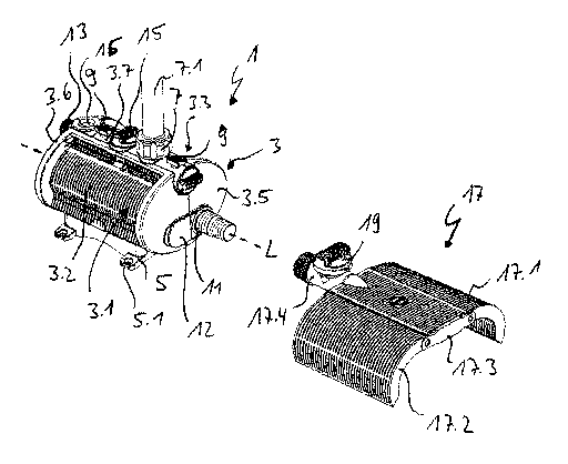
Figure 1 shows a schematic perspective view of a
fountain pump in accordance with the present invention with
the additional filter element detached.
Figure 2 shows a schematic perspective view of the
fountain pump of the invention with the additional filter
element swung out from the housing.
3

20337-616
CA 02497053 2005-02-25
Figure 1 shows a fountain pump 1, which has a
housing 3. The housing 3 has a longitudinal axis and in the
present embodiment is designed with an essentially oval
cross section. The housing 3 has a housing wall 3.1, which
is formed on both longitudinal sides of the housing 3 as
filter surface 3.2 and filter surface 3.3. The filter
surface follows the contour of the housing wall and is thus
outwardly convex, corresponding to the essentially oval
cross section of the housing 3. The filter surfaces 3.2 and
3.3 are designed with grooves and webs in such a way that
coarse material, such as leaves, small twigs, debris, and
even small animals, is retained on the filter when pond
water is drawn into the housing 3. The bottom of the
housing 3 has feet 5 with slotted holes 5.1 formed in them,
with which the housing 3 can also be mounted on mounting
plates, rocks, etc. On the upper side of the housing, a web
3.7 extends from one end face 3.5 of the housing 3 to the
opposite end face 3.6 of the housing 3. The web 3.7
spatially separates the two filter surfaces 3.2 and 3.3 from
each other in such a way that they are arranged parallel to
and symmetrically about the longitudinal axis. A first
outlet 7 is formed on the web 3.7. A telescoping extension
7.1, for example, can be mounted with a water-tight seal on
the first outlet 7. A nozzle to produce the fountain is
installed at the other end. Snap connections 9, with which
two halves of the housing 3 are held together, are also
formed on the web 3.7.
A suction connection 11 is formed on the end face
3.5. The suction connection 11 can be connected with a
threaded insert to allow a hose (not shown) to be attached.
In the absence of a threaded insert of this type, the
suction connection can be covered with a cover 12. The
4

20337-616
CA 02497053 2005-02-25
opposite end face 3.6 is provided with a second outlet 13,
from which water can emerge, for example, for a water spout
or the like. A controller 15 for this second outlet 13 is
formed on the web 3.7. A mounting 16, on which a lighting
fixture for the water spout or fountain can be mounted, is
also formed on the web 3.7.
The end faces 3.5 and 3.6 define the maximum outer
contour of the oval cross section. The filter surfaces 3.2
and 3.3 lie closer to the longitudinal axis, so that they
are positioned a certain radial distance from the outer
contour of the end faces 3.5 and 3.6. The purpose of this
design is to allow the integration of an additional filter
element 17 in the housing 3. This is more clearly
illustrated in Figure 2.
The additional filter element 17 in Figure 1
comprises two filter wings 17.1 and 17.2, which are secured
on a central filter connector 17.3. The central filter
connector 17.3 has a connection 17.4, by which a hose
coupling (not shown) with the suction connection 11 can be
produced, so that even when the additional filter element is
installed at a distance from the housing 3, the two parts
are still functionally connected. A control element 19 is
formed on the connection 17.4, with which the first outlet 7
and the second outlet 13 can be controlled in such a way
that, for example, the water spout and the height of the
fountain can be varied from a location remote from the
housing 3.
In the present embodiment, the filter wings 17.1
and 17.2 of the additional filter element can be secured on
the housing 3 in such a way that they form a continuation of
the circumference determined by the outer contour of the end
5

20337-616
CA 02497053 2005-02-25
faces 3.5 and 3.6 along the entire length of the housing 3.
The filter wings 17.1 and 17.2 thus fit into the recessed
lateral regions of the filter surfaces 3.2 and 3.3 of the
housing 3.
Furthermore, the additional filter element 17 or
the filter wings 17.1 and 17.2 in the present embodiment can
be hinged on the upper side of the housing 3 in the vicinity
of the web 3.7 in such a way that the filter wings 17.1 and
17.2 can be swung out of a first position, in which the
filter wings 17.1 and 17.2 are integrated in the housing in
such a way that they are flush with the end faces of the
housing (not shown), and into a second position (see Figure
2), in which the filter wings no longer rest against the
filter surfaces 3.2 and 3.3.
The additional filter element 17 has one filter
surface on its upper or outer side and one filter surface on
its lower or inner side. As a result, the two opposite main
surfaces of the additional filter element 17 and thus of the
filter wings 17.1 and 17.2 have their own filter
characteristics. In the state shown in Figure 2, in which
the filter wings are swung out, the filter surface is
approximately tripled.
The first outlet 7 on the web 3.7 of the housing 3
is designed in such a way that a nozzle (not shown) mounted
on it can swivel about 20° in all directions.
6

Representative Drawing
A single figure which represents the drawing illustrating the invention.
Administrative Status

2024-08-01:As part of the Next Generation Patents (NGP) transition, the Canadian Patents Database (CPD) now contains a more detailed Event History, which replicates the Event Log of our new back-office solution.

Please note that "Inactive:" events refers to events no longer in use in our new back-office solution.

For a clearer understanding of the status of the application/patent presented on this page, the site Disclaimer , as well as the definitions for Patent , Event History , Maintenance Fee  and Payment History  should be consulted.

Event History

Description Date
Revocation of Agent Requirements Determined Compliant 2008-10-17
Application Not Reinstated by Deadline 2008-08-22
Time Limit for Reversal Expired 2008-08-22
Revocation of Agent Request 2008-08-12
Deemed Abandoned - Failure to Respond to Maintenance Fee Notice 2007-08-22
Letter Sent 2007-05-24
Reinstatement Requirements Deemed Compliant for All Abandonment Reasons 2007-04-10
Inactive: Transfer reinstatement 2007-04-10
Revocation of Agent Requirements Determined Compliant 2006-10-20
Revocation of Agent Request 2006-10-06
Inactive: Status info is complete as of Log entry date 2006-09-18
Inactive: Office letter 2006-09-07
Reinstatement Requirements Deemed Compliant for All Abandonment Reasons 2006-08-22
Inactive: Abandoned - No reply to Office letter 2006-05-29
Inactive: IPC from MCD 2006-03-12
Deemed Abandoned - Failure to Respond to Maintenance Fee Notice 2005-08-22
Inactive: Courtesy letter - Evidence 2005-05-10
Inactive: Cover page published 2005-05-06
Inactive: Notice - National entry - No RFE 2005-05-04
Application Received - PCT 2005-03-17
National Entry Requirements Determined Compliant 2005-02-25
Application Published (Open to Public Inspection) 2004-03-11

Abandonment History

Abandonment Date Reason Reinstatement Date
2007-08-22
2005-08-22

Maintenance Fee

The last payment was received on 2006-08-22

Note : If the full payment has not been received on or before the date indicated, a further fee may be required which may be one of the following

  • the reinstatement fee;
  • the late payment fee; or
  • additional fee to reverse deemed expiry.

Please refer to the CIPO Patent Fees web page to see all current fee amounts.

Fee History

Fee Type Anniversary Year Due Date Paid Date
Basic national fee - standard 2005-02-25
Reinstatement 2006-08-22
MF (application, 2nd anniv.) - standard 02 2005-08-22 2006-08-22
MF (application, 3rd anniv.) - standard 03 2006-08-22 2006-08-22
Reinstatement 2007-04-10
Registration of a document 2007-04-10
Owners on Record

Note: Records showing the ownership history in alphabetical order.

Current Owners on Record
OASE GMBH
Past Owners on Record
DIETER HOFFMEIER
Past Owners that do not appear in the "Owners on Record" listing will appear in other documentation within the application.
Documents

To view selected files, please enter reCAPTCHA code :


To view images, click a link in the Document Description column. To download the documents, select one or more checkboxes in the first column and then click the "Download Selected in PDF format (Zip Archive)" or the "Download Selected as Single PDF" button.

List of published and non-published patent-specific documents on the CPD .

If you have any difficulty accessing content, you can call the Client Service Centre at 1-866-997-1936 or send them an e-mail at CIPO Client Service Centre.


Document
Description 
Date
(yyyy-mm-dd) 
Number of pages   Size of Image (KB) 
Claims 2005-02-25 2 67
Abstract 2005-02-25 2 90
Description 2005-02-25 6 223
Representative drawing 2005-02-25 1 47
Drawings 2005-02-25 2 44
Cover Page 2005-05-06 1 61
Reminder of maintenance fee due 2005-05-04 1 110
Notice of National Entry 2005-05-04 1 192
Courtesy - Abandonment Letter (Maintenance Fee) 2005-10-17 1 176
Request for evidence or missing transfer 2006-02-28 1 100
Courtesy - Abandonment Letter (Office letter) 2006-07-10 1 166
Notice of Reinstatement 2007-05-24 1 171
Courtesy - Certificate of registration (related document(s)) 2007-05-24 1 107
Courtesy - Abandonment Letter (Maintenance Fee) 2007-10-17 1 173
Reminder - Request for Examination 2008-04-23 1 126
PCT 2005-02-25 12 364
PCT 2005-02-25 1 47
Correspondence 2005-05-04 1 25
Correspondence 2006-09-07 1 21
Fees 2006-08-22 2 59
Correspondence 2006-10-06 1 29
Correspondence 2007-04-10 2 75
Correspondence 2008-08-12 1 30
Correspondence 2008-10-17 1 14
Correspondence 2008-10-17 1 20