Note: Descriptions are shown in the official language in which they were submitted.
CA 02497140 2005-02-25
Case 2183 Amended description, pages 1, 2
WATCH INCLUDING iN THE BACK OF ITS CASE AN ELECTRONIC
MODULE FOR STORING INFORMATION
The present invention relates to watches, generally wristwatches, whose
cases incorporate electronic modules for storing information that comprise an
integrated circuit or chip connected to an antenna consisting of a coil and
are able to
communicate by radio signals with a reading and/or writing device adapted at
least to
read the information contained in a memory of the integrated circuit and often
also
adapted to delete or modify at least some of that information and to add other
information.
To be more precise, the invention relates to watches in which the electronic
modules are passive, meaning that these modules do not need their own power
supply, such as batteries or rechargeable batteries, to be able to operate,
being
supplied with power by the radio signals from the reading and/or writing
device with
which they co-operate.
Some watches of the above kind merely store an access code to private or
protected premises or to ski slopes, for example. Others include electronic
modules
equipped with more complicated integrated circuits and may contain the medical
records of their owner.
In some prior art watches, the electronic module is placed in a hollow and
preferably removable bezel so that the module can be changed if necessary.
This
solution may therefore not be suitable for watches having any type of case.
Moreover, if the case actually includes a bezel or a case-bezel, this
complicates its
fabrication and consequently increases the unit cost of the watch.
The document JP 2000-339503 describes a watch of the above kind that
comprises an electronic module mounted on the outside of the watch glass. One
drawback of placing said module on the glass is that it cannot be protected
from
mechanical shock when the user is wearing the watch. Also, as it is in front
of the
watch dial, it is always visible, which degrades the aesthetics of the watch.
In other watches the module is placed in a space between the rear of the
movement of the watch and the back of the case, which necessarily increases
their
volume. If the back of the case is made from a material that is not really
amagnetic,
such as steel, the magnetic flux emitted or received by the coil of the
electronic
module suffers high losses, and even if measures are taken to limit these
losses,
they are far from negligible. Finally, even if the back of the case is made
from an
amagnetic material, for example a plastic material, radio signals emitted and
received
CA 02497140 2005-02-25
by the coil of the module, which have to pass through the whole of the
thickness of
the back, suffer high attenuation.
The object of the invention is to provide a watch, in particular a wristwatch,
that completely eliminates or at least reduces the drawbacks of the above
prior art
watches.
To achieve the above object, the watch has the features set out in claim 1.
Advantageous embodiments of the watch are defined in the dependent claims
2 to 8.
The cavity and the module preferably have an essentially cylindrical shape
and are preferably situated at the centre of the back of the case.
Accordingly, unlike a watch in which the module is placed at the back of the
case and entirely within it, in the watch of the invention signals emitted and
received
by the coil of the module have to pass only through the base of the module,
which is
much thinner than the back of the case.
It is possible to obtain a watch of the invention starting with an existing
watch
by forming in its back a blind hole with a shape adapted to that of the
electronic
module.
If the back of the case is removable, it is possible to replace it to convert
an
ordinary watch into a watch of the invention.
This being so, in one embodiment of the watch of the invention, the base of
the module is cup-shaped and has a flat bottom to which the coil and the
integrated
circuit are fixed and a lateral wall around the coil.
This embodiment is particularly suitable if the back of the case is made from
a
magnetic material such as steel.
The invention will be better understood after reading the following
description,
which is given by way of example and with reference to the appended drawings,
of
several embodiments of the invention, in which drawings:
- figure 1 is a diagrammatic view in diametral section of an analogue display
wristwatch of the invention;
- figure 2 is a view in diametral section to a larger scale of the portion of
the
back of the figure 1 case which accommodates a first embodiment of an
electronic
module incorporated into the back;
- figure 3 is an incomplete plan view of the electronic module shown in figure
2, showing how the ends of the wire of its coil are connected to respective
terminals
of the integrated circuit of the module;
CA 02497140 2005-02-25
-3-
- figure 4 is a view in section analogous to that of figure 2 of a second
embodiment in which the ends of the wire of the coil of the electronic module
are
connected in a different way to the terminals of its integrated circuit;
- figure 5 is a view analogous to that of figure 3 for the figure 4 mode of
connecting the integrated circuit and the coil; and
- figures 6 and 7 are views analogous to that of figure 2 showing other
embodiments of electronic modules that can be incorporated into the back of a
watch
case of the invention.
Although the invention is obviously not limited to this application, the
following
description applies to the situation in which the electronic module fitted to
the watch is
designed to store information that relates to the watch itself and to be
placed at a very
small distance (a few millimetres at the most) from the coil that constitutes
the send
and receive antenna of a reading and/or writing device with which it is able
to
communicate.
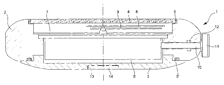
The wristwatch shown diagrammatically in figure 1 comprises a case 1 that
consists of a metal case-bezel unit 2, a metal back 3 and a glass 4 clamped to
the
case-bezel unit 2 in the conventional way by means of a gasket 5 which also
seals the
glass to the case.
Figure 1 shows the back 3 clipped to the case-bezel unit 2, but the back could
equally well be screwed to it or fixed to it by means of a bayonet system in
such a
manner as to compress a gasket 5' that seals the back to the case.
The case 1 finally comprises a wrist-band attachment system that is not
visible
in figure 1 and may comprise two pairs of horns on the case-bezel unit 2.
The case 1 houses a movement 6 which drives a minute hand 8 and an hour
hand 9 placed in front of a dial 7 and which comprises a control spindle 10
that passes
through the case-bezel unit 2 and terminates in a crown 11, an O-ring 12
sealing the
case 1 where the spindle passes through the case-bezel. If the watch is not of
the
electromechanical or self-winding type, the spindle 10 and the crown 11 are
also used
to wind the watch.
In accordance with the invention, the back 3 of the case 1 has a cavity 13
that
is open towards the exterior of the case and houses an electronic module 14,
the
cavity and the module preferably being essentially cylindrical and situated at
the
centre of the back 3.
Given that, in the application envisaged here, the electronic module 14 has a
much smaller area than the back of the case and the module can be made in
various
shapes, it is merely represented in figure 1 by a rectangle.
CA 02497140 2005-02-25
-4-
Figure 2 is a view in section to a larger scale of part of the back 3 of the
case 1
from figure 1 and shows one embodiment of the electronic module 14 that is
adapted
to be inserted permanently into the cavity 13 in the back.
In this embodiment, the module 14 comprises a base 15 made from an
amagnetic and electrically insulative material. This material may be a plastic
material
such as high-density polyethylene or a ceramic material, for example, plastic
materials
being reserved for bottom of the range watches and middle of the range watches
and
ceramic materials for top of the range watches. In the fatter case the ceramic
material
preferably has substantially the same colour and the same appearance as the
metal
that constitutes the back of the case, unless a particular aesthetic effect is
required.
As shown in figure 2, the base 15 is cup-shaped and has a flat bottom 16 and
an essentially cylindrical lateral wall 17. This figure also shows that the
thickness of
the wall 17 increases slightly and continuously from its base to its top so
that its
exterior surface 18 has a particular shape enabling it to co-operate with the
internal
wall 19 of the cavity 13, which has a complementary shape, to constitute a
dovetail
joint.
The external edge 20 of the wall 17 of the base and the rim 21 of the wall 19
of
the cavity 13 are rounded to facilitate insertion of the module 14 into the
cavity.
Figure 3 is a plan view of the electronic module 14 from figure 2 without an
adhesive filler material referred to hereinafter.
Referring to figures 2 and 3, it can be seen that the lateral wall 17 of the
base
15 has a truly cylindrical internal surface 22 which surrounds a flat and self-
supporting
annular coil 23, to be more precise a cylindrical coil. In the manner known in
the art,
the coil consists of a plurality of layers of contiguous and coaxial turns,
not visible in
the drawing, made from a very thin metal wire 28, preferably copper wire,
covered with
a sheath or an insulative and thermo-adhesive material that is partially
melted by
heating it so that all the portions of the sheath that surround the turns of
wire are
welded together when the coil is allowed to cool afterwards.
The coil 23 itself surrounds an integrated circuit 24 smaller than itself, of
rectangular parallelepiped shape, and which has on its front face 25 two
connecting
terminals or "bumps" 26 and 27 to which the two ends 29 of the metal wire of
the coil
23 are welded or fixed by means of a conductive adhesive.
The two connecting terminals 26 and 27 of the integrated circuit 24 shown in
figures 2 and 3 are disposed opposite each other in the lengthwise direction
of the
integrated circuit 24, but it is clear that they could be otherwise disposed
on the front
surface of the integrated circuit, for example side by side in its widthwise
direction.
CA 02497140 2005-02-25
-5-
In this first embodiment, the coil 23 and the integrated circuit 24 are fixed
directly to the internal face 30 of the flat bottom 16 of the base 15 by means
of a thin
layer of adhesive material 31 (see figure 2) and the space inside the coil
left free by
the integrated circuit is filled with an adhesive and insulative thermosetting
material
32, for example an epoxy resin, to protect the ends 29 of the wire of the coil
23 and
the means fixing them to the connecting terminals 26 and 27 before the module
14 is
incorporated into the back of the watch case. The adhesive material 32 is
preferably
opaque so that it also protects the integrated circuit against light before it
is
incorporated into the back of the watch case.
The base 15 has or may have three functions.
Firstly, if the back 3 of the case 1 is made from a magnetic material, for
example steel, this amagnetic material base serves as a screen between the
back and
the coil, to eliminate, if not totally, at least the majority of the magnetic
flux losses in
the back 3 when the coil sends and receives radio signals respectively to and
from a
reading andlor writing device to which it may be coupled.
Secondly, as shown in figure 2, the module 14 projects slightly from the
external face 33 of the back 3 of the case 1 to form a boss 34 adapted to
position it
optimally and quickly on a head 35 of a reading andlor writing device shown
partly and
diagrammatically in dashed outline in figure 2 and which itself comprises an
antenna
36 in the form of a coil. This head, which incorporates a recess 35' whose
shape and
dimensions correspond to those of the boss 34, may be connected via an
interface to
a device specifically designed to communicate with the memory of the watch,
preferably a fixed or portable personal computer (PC).
Obviously, the boss 34 of the module would enable the watch to be placed in
the same way on any support having a recess corresponding to the shape and
dimensions of the boss.
If the module projects from the back of the case 1, its external edge 37 is
preferably rounded to prevent the boss 34 causing discomfort to the wearer of
the
watch.
In all cases, it is clear that, because radio waves emitted and received by
the
coil 23 of the module 14 no longer have to pass through the whole of the
thickness of
the back 3 of the case 1 of the watch, but only that of the bottom 16 of the
base of the
module, which is much thinner, these radio waves will be much less attenuated
and
distorted than in prior art watches in which the electronic module is placed
at the
bottom but inside the case.
Until now, only one memory has been referred to in relation to the integrated
circuit 24. It is nevertheless clear that this circuit could comprise a
plurality of
CA 02497140 2005-02-25
-6-
memories of different types, in particular memories for storing information
that can
only be read and other memories for storing other information that can also be
deleted
and/or modified or have additional information added to it.
This is the situation in the application example previously referred to in
which
the electronic module stores information relating to the watch itself, to be
more precise
its source, its purchaser and, just like a car, its "service record"; this
information
personalises the watch, which may be of benefit on selling the watch or
facilitate the
task of a watchmaker if the watch is passed to him for inspection or repair or
simply
for him to change the battery if the watch is of the electromechanical or
electronic
type.
In the case of middle of the range and top of the range watches, the stored
information may be divided into the following four categories, for example:
1- "Brand" and model name or number under which the watch was sold,
and where applicable a code specific to the brand, and a date on which and an
address to which the watch was shipped to a retailer.
2- "Plant": name or sign of the company having manufactured the watch
movement if this is not the same as the company selling the watch, and
internal
designation of the movement.
3- "Point of sale": retailer name and address, date of purchase and name of
purchaser.
4- "Customer services": some or al! of the above information, plus the date
of and information on servicing carried out by the vendor or another retailer
(for
example adjustment, testing, battery replacement) and in the latter case the
name and
address of the other retailer.
Some of the above information may be stored in a ROM memory so that it can
only be read. This applies to the "Brand" and "Plant" information referred to
above.
The other information ("Point of sale", "Customer services") may be stored in
one or more dynamic RAM, EPROM or EEPROM memory so that it can be deleted,
modified or added to, if necessary.
The stored information depends also on the type of watch in whose case the
electronic module is incorporated. Far example, in the case of a bottom of the
range
watch whose case is of one-piece construction with a welded-on glass that
prevents
all possibility of working inside the watch, with the possible exception of
changing the
battery or having the battery changed if the watch is of the electromechanical
or digital
kind and under warranty, just the "Brand" and "Plant" information may be
stored in
read-only memory.
CA 02497140 2005-02-25
7-
In all cases, the coil of a read head or of a support may be connected via an
appropriate interface to a fixed or portable computer able to read the
information
contained in the memory or memories of the module and where applicable to
delete,
modify and add to some of that information.
This information may be sent to a protected Internet site or over an Intranet
loop to which all persons involved with the watch have access.
Figures 4 and 5 are analogous to figures 2 and 3 and show a second
embodiment of the electronic module of a watch of the invention. In these
figures, the
same and corresponding components are designated by the same reference
numbers, and only new components are indicated by new reference numbers.
One of the differences between the embodiment of figures 4 and 5 and that of
figures 2 and 3 is that the coil 23 and the circuit 24 are no longer stuck
directly to the
internal face of the bottom 16 of the module 14, but instead to the substrate
38 of a
printed circuit 39 which may itself be stuck to the bottom 16 of the base 15
of the
module 14 or merely set into the base.
The other difference is that the ends of the wire 29 of the coil 23 no longer
connect the coil to the terminals 26 and 27 of the integrated circuit 25
directly but
instead via connecting lands 40 formed on the substrate 38 of the printed
circuit 39.
To be more precise, each end of the wire 29 is welded or stuck by means of an
electrically conductive adhesive to one of the lands 40 which is in turn
connected to a
connecting terminal 26 or 27 of the integrated circuit 24 by a conductive wire
41.
Thanks to this the coil 23 and the integrated circuit 24 can be electrically
connected using the standard automated wire bonding method.
In the embodiment shown in section in figure 6, the exterior surface 18 of the
lateral wall 17 of the base 15 and the internal wall 19 of the cavity 13 in
the back 3 of
the watch case are both true cylinders and the module 14 is set into the
cavity or
adhesively bonded to the interior of the cavity. The external edge 21 of the
wall 17 and
that of the module 14 are not rounded as in the embodiment of figures 2 and 3,
but
right-angled.
This embodiment is more suitable if the back 3 of the case and/or the base 15
of the module 14 are made from very hard materials that are difficult to
machine or
shape, such as certain ceramic materials or sapphire.
In this embodiment, as in that of figures 2 and 3, the ends of the wire of the
coil
23 are fixed directly to the connecting terminals 26 and 27 of the integrated
circuit 24,
but it is obvious that these ends of the wire and these terminals 26 and 27
could be
connected in the same way as in the embodiment of figures 4 and 5.
CA 02497140 2005-02-25
_ $ _
Note that in a different embodiment, not shown in the drawings, the module 14
could be crimped into the cavity 13 in the back 3 of the case. The base 15 of
the
module would then have on the same side as its bottom 16 an external
peripheral cut-
out in which an internal rim of the back 3 would engage. This method of fixing
the
module could be used if it were not possible to set it into the case or
adhesively bond
it to the case, for example.
Unlike the figure 6 embodiment, which is reserved for top of the range
watches, that shown in section in figure 7, which is much simpler and more
economical, is very suitable for bottom of the range watches in which the back
is
made from a plastic material, for example.
In this case, the base 15 is reduced to a simple rigid plate of the same
diameter as the outside diameter of the coil 23, and which may be made from
the
same material as the back of the case, in which eventuality the module 14 may
be set
into or adhesively bonded in the cavity 13 in the back of the case.
The above remarks as to the connection between the ends of the wire of the
coil and the terminals of the integrated circuit are equally valid for this
embodiment.
Clearly the invention is not limited to the embodiments or variants that have
just been described or envisaged.
For example, instead of connecting the ends of the wire of the coil to the
terminals of the integrated circuit by means of connecting lands using the
wire
bonding technique, this connection could be obtained using another well-known
automated technique known as tape automated bonding (TAB), which is described
in
European Patent No. 0 376 062.
Although the method is described in that patent for producing electronic
modules intended to be incorporated totally into electronic keys or cards, it
is very
suitable for producing modules to be fitted to watches of the invention.
In all the embodiments described or envisaged hereinabove, the back of the
electronic module is proud of the exterior surface of the back of the case of
the watch,
but this is not obligatory.
In these embodiments and variants, the electronic module is fixed permanently
into the cavity in the back of the case, but it would be entirely feasible to
design a
module with a base provided with a lateral wall enabling it to co-operate with
an
internal wall of the cavity in the back so as to render the module removable,
and
where applicable interchangeable, for example by means of a screwing or
bayonet
fixing system.
In this eventuality, it would obviously be necessary to provide means for
extracting the module from the cavity in the back of the case and replacing
the same
CA 02497140 2005-02-25
_g_
module or substituting a replacement module. Those means could be a groove in
the
exterior face of the module, for example, like those provided for battery
compartment
covers in electromechanical or electronic watches.
Finally, another option would be to modify the characteristics of the antenna
coil, in particular its diameter and the number of turns, to enable it to
communicate
with the antenna of a reading andlor writing device not at a distance of a few
millimetres but at a distance of a few centimetres or tens of centimetres.