Some of the information on this Web page has been provided by external sources. The Government of Canada is not responsible for the accuracy, reliability or currency of the information supplied by external sources. Users wishing to rely upon this information should consult directly with the source of the information. Content provided by external sources is not subject to official languages, privacy and accessibility requirements.
Any discrepancies in the text and image of the Claims and Abstract are due to differing posting times. Text of the Claims and Abstract are posted:
| (12) Patent Application: | (11) CA 2497576 |
|---|---|
| (54) English Title: | METHOD FOR THE SEPARATION OF RESIDUAL GASES AND WORKING FLUID IN A COMBINED CYCLE WATER/STEAM PROCESS |
| (54) French Title: | PROCEDE PERMETTANT DE SEPARER DES GAZ RESIDUELS ET UN FLUIDE DE TRAVAIL LORS D'UN PROCESSUS A CYCLE COMBINE EAU/VAPEUR |
| Status: | Deemed Abandoned and Beyond the Period of Reinstatement - Pending Response to Notice of Disregarded Communication |
| (51) International Patent Classification (IPC): |
|
|---|---|
| (72) Inventors : |
|
| (73) Owners : |
|
| (71) Applicants : |
|
| (74) Agent: | SMART & BIGGAR LP |
| (74) Associate agent: | |
| (45) Issued: | |
| (86) PCT Filing Date: | 2003-07-14 |
| (87) Open to Public Inspection: | 2004-01-29 |
| Availability of licence: | N/A |
| Dedicated to the Public: | N/A |
| (25) Language of filing: | English |
| Patent Cooperation Treaty (PCT): | Yes |
|---|---|
| (86) PCT Filing Number: | PCT/DE2003/002366 |
| (87) International Publication Number: | DE2003002366 |
| (85) National Entry: | 2005-03-04 |
| (30) Application Priority Data: | ||||||
|---|---|---|---|---|---|---|
|
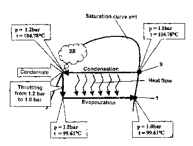
The invention relates to a method for the separation of residual gases and
working fluid in a combined cycle water/steam process, which provides for the
multi-stage compression and multi-stage expansion of the mixture of working
fluid and reaction products from the additional liquid and/or gaseous fuels,
by the use of steam. The aim of the invention is the minimisation of the
working fluid losses and minimisation of the additional necessary energy use.
Said aim is achieved, whereby the expanded exhaust gas from the high pressure
turbine stage (19) is subjected to a cooling process which cools the same to
the condensation temperature of the steam contained in the exhaust gas (6).
The non-condensed parts of the exhaust gas (6) are bled off, whereby the
condensation of the working fluid, the bleeding off of non-condensed residual
gases (25), the depressurisation of the working fluid condensate and the
evaporation of the condensed working fluid are carried out in a residual gas
separator (10).
L'invention concerne un procédé permettant de séparer des gaz résiduels et un fluide de travail lors d'un processus à cycle combiné eau/vapeur, au cours duquel la compression multiétagée et la détente multiétagée du mélange constitué par le fluide de travail et les produits de la réaction entre les autres combustibles liquides et/ou gazeux s'effectuent à l'aide de vapeur d'eau. L'objectif de cette invention est de minimiser les pertes de fluide de travail et de minimiser l'énergie supplémentaire nécessaire. A cet effet, le gaz de combustion détendu (6) issu de l'étage de turbine haute pression (19) est soumis à un processus de refroidissement jusqu'à ce qu'il parvienne à la température de condensation de la vapeur d'eau contenue dans ce gaz de combustion (6) et les fractions non condensées du gaz de combustion (6) sont évacuées, la condensation du fluide de travail, l'évacuation des gaz résiduels non condensés (25), la détente du condensat de fluide de travail ainsi que l'évaporation du fluide de travail condensé étant effectuées dans un séparateur de gaz résiduels (10).
Note: Claims are shown in the official language in which they were submitted.
Note: Descriptions are shown in the official language in which they were submitted.
2024-08-01:As part of the Next Generation Patents (NGP) transition, the Canadian Patents Database (CPD) now contains a more detailed Event History, which replicates the Event Log of our new back-office solution.
Please note that "Inactive:" events refers to events no longer in use in our new back-office solution.
For a clearer understanding of the status of the application/patent presented on this page, the site Disclaimer , as well as the definitions for Patent , Event History , Maintenance Fee and Payment History should be consulted.
| Description | Date |
|---|---|
| Application Not Reinstated by Deadline | 2008-07-14 |
| Time Limit for Reversal Expired | 2008-07-14 |
| Deemed Abandoned - Failure to Respond to Maintenance Fee Notice | 2007-07-16 |
| Letter Sent | 2006-05-23 |
| Inactive: Single transfer | 2006-04-12 |
| Inactive: IPRP received | 2005-09-16 |
| Inactive: Courtesy letter - Evidence | 2005-05-10 |
| Inactive: Cover page published | 2005-05-09 |
| Inactive: Notice - National entry - No RFE | 2005-05-03 |
| Correct Applicant Requirements Determined Compliant | 2005-05-03 |
| Inactive: Applicant deleted | 2005-05-03 |
| Inactive: Applicant deleted | 2005-05-03 |
| Inactive: Applicant deleted | 2005-05-03 |
| Inactive: Correspondence - Formalities | 2005-04-25 |
| Application Received - PCT | 2005-03-22 |
| National Entry Requirements Determined Compliant | 2005-03-04 |
| National Entry Requirements Determined Compliant | 2005-02-11 |
| Application Published (Open to Public Inspection) | 2004-01-29 |
| Abandonment Date | Reason | Reinstatement Date |
|---|---|---|
| 2007-07-16 |
The last payment was received on 2006-07-04
Note : If the full payment has not been received on or before the date indicated, a further fee may be required which may be one of the following
Patent fees are adjusted on the 1st of January every year. The amounts above are the current amounts if received by December 31 of the current year.
Please refer to the CIPO
Patent Fees
web page to see all current fee amounts.
| Fee Type | Anniversary Year | Due Date | Paid Date |
|---|---|---|---|
| Reinstatement (national entry) | 2004-03-04 | ||
| Basic national fee - standard | 2004-03-04 | ||
| MF (application, 2nd anniv.) - standard | 02 | 2005-07-14 | 2005-07-11 |
| Registration of a document | 2006-04-12 | ||
| MF (application, 3rd anniv.) - standard | 03 | 2006-07-14 | 2006-07-04 |
Note: Records showing the ownership history in alphabetical order.
| Current Owners on Record |
|---|
| RERUM COGNITIO GESELLSCHAFT FUER MARKTINTEGRATION DEUTSCHER INNOVATION UND FORSCHUNGSPRODUKTE MBH |
| Past Owners on Record |
|---|
| WOLFGANG HARAZIM |

