Note: Descriptions are shown in the official language in which they were submitted.
CA 02497865 2010-10-29
23422-191
[0001] METHOD AND DEVICE FOR INTRODUCING LIQUIDS INTO A
FLOW OF SOLIDS OF A SPOUTED BED APPARATUS
[0002] The invention relates to a process for depositing fluids in a solids
flow of a spouted bed apparatus, for which the fluids are introduced through a
nozzle into the spouted bed, and an associated apparatus for introducing
fluids
into a solids flow of a spouted bed apparatus, in which a spray nozzle opens
into a
reaction space of the spouted bed apparatus.
[0003] From DE 31 17 892 Al, a spouted bed apparatus for producing
granulates is known, for which a fluid is introduced into the solids flow of
the
spouted bed granulator. The spouted bed apparatus has a round cross section,
whose lower part is formed with a conical taper. A gas channel, where a nozzle
for injecting the fluid is arranged, opens into the central conical part of
the spouted
bed granulator. An appropriate gas is fed through the gas channel for
maintaining
the spouted bed. The centrally fed gas entrains the fluid introduced by the
nozzles and a portion of the material located in the spouted bed granulator,
wherein a stream channel is produced in which the material particles are
wetted
with the fluid. The sprayed material is fed back to the stream channel over
the
conical base, so that particle circulation is generated. After achieving an
adequate
granulate size, the granulates are discharged from the spouted bed granulator.
[0004] A disadvantage for this type of spouted bed granulator is that the
supply of gas for generating the spouted bed and the introduced fluid is
supplied
at a common location in the lower part of the spouted bed granulator. A
uniform
wetting of all material particles to be treated with fluid is hard or
impossible to
realize. Some material particles are sprayed with too much and others with too
little fluid, so that an end product with equal grain size and equal material
structure
cannot be realized. In addition, these systems are only suitable for
granulation at
low material throughputs. For greater throughputs, problems appear in terms of
generating and maintaining the spouted bed.
1
CA 02497865 2010-10-29
23422-191
[00051 Previously known from the publication DE 100 04 939 C1 is a spouted
bed apparatus for fluidization and thermal treatment of essentially
arbitrarily
shaped materials with different particle dimensions as well as particle
masses. The
spouted bed apparatus for batch or continuous process control consists of a
inlet air
chamber arranged in the lower region of the spouted bed apparatus, into which
the
fluidizing means, such as, especially air, is supplied. The fluidizing means
is fed to
the fluidization region of the spouted bed apparatus by means of a
controllable gas
flow device arranged between the inlet air chamber and the fluidization
region. The
fluidization region is formed by the gas flow device arranged in the lower
region, as
well as by a stream inlet wall, a stream return flow wall lying opposite the
stream
inlet wall, and also the side walls. The stream inlet wall and the stream
return flow
wall are inclined relative to the vertical, so that they form a cone.
Therefor:, an
expanded cross section of the spouted bed apparatus is formed above the stream
inlet wall and the stream return flow wall. This expanded section is used as
an
expansion region for the fluidizing means and is provided with an outlet for
the
exhaust air. The spouted bed apparatus can be one-sided or two-sided, i.e.; it
can be
formed with a double cone. Through the arrangement of the stream inlet wall
and
the stream return flow wall as well as through the supply of fluidizing means
through the gas flow device, a type of solids rotation is produced in the
fluidization
region, in which a corresponding material treatment is performed.
[0006] An introduction of fluids into the solids flow is not provided with
this
type of stream apparatus.
[0007] The object of some embodiments of the invention is to create for a
spouted bed apparatus a process and an associated apparatus with which a fluid
can be
selectively and adjustably deposited on the material in the spouted bed for
producing
coated granulates, for wetting material particles, and the granulation and
agglomeration
of different materials for a wide range of industrial branches, so that an end
product is
produced with approximately equal grain size and equal material properties
even for
large material throughputs.
2
CA 02497865 2010-10-29
23422-191
[0008] An aspect of the invention provides a process for introducing fluids
into a solids flow of a spouted bed apparatus, for which the fluids are
introduced
through a nozzle into the spouted bed, wherein: in a reaction space of the
spouted
bed apparatus provided with a rectangular cross section, at least one circular
solids flow in the axial direction of the reaction space is generated, a fluid
is
injected into the solids flow, the solids flow is formed with an upwards flow
with a
high flow rate, with a cross flow with a lower flow rate, and with a downwards
flow,
which has a lower flow rate than the cross flow, by the supply of inlet air
through a
gap in the lower region and in the axial direction of the reaction space and
by the
injected fluid.
[0008a] Another aspect of the invention provides an apparatus for
introducing fluids into a solids flow of a spouted bed apparatus, in which a
spray
nozzle opens into a reaction space of the spouted bed apparatus, wherein a
lower
region of the reaction space is provided with a rectangular cross section for
the
spouted bed apparatus and is limited in an axial direction by at least one
inclined
stream return flow wall and an oppositely inclined stream inlet wall with the
formation of an axial gap through the reaction space for supplying inlet air
and at
least one nozzle for introducing fluid above the gap opens into the reaction
space.
[0009] Through the formation of at least one circular solids flow in the axial
direction of the reaction space of the spouted bed apparatus, for which the
inlet air
required for forming the solids flow is fed over a gap in the lower region and
in the
axial direction of the reaction space and the fluid is introduced by means of
one or
more single and/or multiple-component nozzles at one or more positions in the
solids flow, the flow conditions in the injection region can be set so that
the fluid
can be introduced selectively and adjustably into the solids flow. The
resulting
end product distinguishes itself through approximately equal grain size with
equal
material properties. By spraying pure fluids, solutions, molten masses, or the
like
through one or more single and/or multiple-component nozzles into the solids
flow,
different end products can be produced.
3
CA 02497865 2010-10-29
23422-191
[0010] Another advantage of the solution according to some embodiments
of the invention is that with the proposed process and apparatus, the material
to
be treated can be exposed to various technologies, such as granulation,
agglomeration, wetting, and coating.
[0011] Additional advantageous configurations are described and explained
in the description together with their effect.
[0012] The invention is explained in more detail in the following with
reference to an embodiment. Shown in the associated drawings are:
[0013] Figure 1 is a sectional view of a spouted bed apparatus according to
an embodiment of the invention,
[0014] Figure 2 is a perspective view of a variant of the spouted bed
apparatus according to an embodiment of the invention,
[0015] Figure 3 is a sectional view of another variant of the spouted bed
apparatus according to an embodiment of the invention, and
[0016] Figure 4 is a perspective view of several reaction spaces arranged
one next to the other for the spouted bed apparatus according to an embodiment
of the invention.
3a
CA 02497865 2010-10-29
23422-191
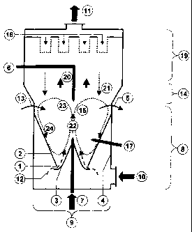
[0017] In Figure 1, a spouted bed apparatus is shown, whose apparatus cross
section 9 features a rectangular cross section. In Figure 2, a section of the
spouted
bed apparatus shown in Figure 1 is illustrated in perspective. The fundamental
construction of the spouted bed apparatus includes a inlet air chamber 8, an
expanding cross-section expansion region 14 arranged above this chamber, and a
dedusting system 19. In the housing 4 of the flow apparatus, there is a supply
port
for the inlet air 10 in the lower part of the inlet air chamber 8, while in
the upper
region of the spouted bed apparatus there is an outlet for the exhaust air 11.
The
dedusting system 19 is provided with a known filter cleaning device 18, which
feeds
the separated dust into the reaction space 26 of the spouted bed apparatus.
[0018] In the region of the inlet air chamber 8, the housing 4 of the spouted
bed apparatus, as viewed in the axial direction, has at least one stream
return flow
wall 2 and one stream inlet wall 3, which define the actual reaction space 26
of the
spouted bed apparatus. Figure 1 shows a preferred variant of the formation of
reaction space 26, for which the lower region of the reaction space 26 is
limited in
the axial direction by two inclined stream return flow walls 2, which are each
associated with an inclined stream inlet wall 3 under the formation of two
axial
gaps 1. These return flow walls are connected together in the top region.
However,
the lower region of the reaction space 26 can also be formed by only one
inclined
stream return flow wall 2 and an opposing inclined stream inlet wall 3 under
the
formation of an axial gap 1 running through the reaction space 26 for
supplying
inlet air 10. Controllable valve devices for setting the amount and the rate
of the air
flow 12 fed to the reaction space 26 are arranged in the gap 1. The gap 1 is
formed
such that the air flow 12 of the inlet air 10 is fed against the lower region
of the
stream inlet wall 3.
[0019] The material to be treated is fed into the reaction space 26 through a
material inlet 13, wherein under the effect of the supplied air flow 12, a
circular
solids flow 15 is formed in the axial direction of the reaction space 26. The
material
inlet 13 preferably opens in the region of a flow 24 of the downwards solids
flow 15
-4-
CA 02497865 2010-10-29
23422-191
into the reaction space 26. The material leaves the reaction space 26 through
a
solids outlet 5, wherein the solids outlet 5 is arranged in the region of the
transition
of the cross flow 23 to the solids flow 24 of the downwards solids flow 15.
[0020] For introducing fluid into the solids flow 15, at various positions
above
the gap 1 one or more nozzles 6, 7, 17 open into the reaction space 26. Here,
the
nozzles 7 act in the direction of the upwards flow 22, the nozzles 6 act
against the
direction of the upwards flow 22, and the nozzles 17 are arranged in the
region of
the downwards flow 24. Several nozzles 6 and/or 7 and/or 17 arranged one next
to
the other in the axial direction of the reaction space 26 open into the
reaction space
26 of the spouted bed apparatus.
[0021] As can be seen from Figure 2, an axial separating plate 16, whose
lower edge is at a distance to the stream return flow wall 2, is arranged in
the lower
region of the reaction space 26 between the stream return flow wall 2 and the
stream inlet wall 3.
[0022] In Figure 3, a spouted bed apparatus is shown without an integrated
dedusting system 19. Here, the dust-bearing exhaust air 20 is discharged as
exhaust air 11 from the spouted bed apparatus and is dedusted in a downstream,
separate dedusting system that is not shown.
[0023] In Figure 4, a multi-stage spouted bed apparatus is shown, which is
formed from several reaction spaces 26 arranged one next to the other. Here,
two
adjacent reaction spaces 26 are connected to each other over a common overflow
port, which is formed for the first reaction space as a solids discharge 5 and
for the
second reaction space as a solids inlet 13. Here, the lower region of the
inlet air
chamber 8 can be divided into several segments through the arrangement of
separating walls 25, which enclose one or more reaction spaces 26. Inlet air
10 can
be supplied in different amounts, temperatures, and flow rates into the spaces
produced here for the reaction spaces 26.
[0024] The effect of the spouted bed apparatus is explained in more detail
with reference to the following process according to the invention.
-5-
CA 02497865 2005-03-04
[0025] The process according to the invention for introducing fluid into a
solids flow of a spouted bed apparatus for producing coated granulates, for
wetting
material particles, and for the granulation and agglomeration of different
materials
for a wide range of industrial branches, generates at least one circular
solids flow 15
in the axial direction of the reaction space 26, in which a fluid is injected.
Here, the
solids flow 15 is formed with an upwards flow 22 with a high flow rate, with a
cross
flow 23 with a lower flow rate, and with a downwards flow 24, which has a
lower
flow rate than the cross flow 23, by supplying inlet air 10 through a gap 1 in
the
lower region and in the axial direction of the reaction space and by the
injected
fluid. The downwards solids flow 24 in the reaction space 26 is generated by
the
effect of gravity.
[0026] The material to be treated is transported by the circular solids flow
15
through the elongated reaction space 26 from the material inlet 13 to the
solids
outlet 5, wherein the material is sprayed with fluid by means of the nozzles 6
and/or
7 and/or 17 arranged one behind the other in the axial direction of the
reaction
space 26. Here, the fluid is introduced by means of single and/or multiple-
component nozzles 6, 7, 17 at one or more positions in the solids flow 15.
Corre-
sponding to the end product to be produced, a pure fluid, solution, molten
mass, or
the like is sprayed into the solids flow 15. Through correspondingly set flow
ratios
in the reaction space 26 and through the supply of fluids into the solids flow
15, a
wetting, coating, or a granulation or agglomeration of the material is
performed
corresponding to the end product to be produced.
[0027] For forming the solids flow 15 with a desired flow profile, the amount
and the flow rate of the inlet air 10 supplied to the reaction space 26 and/or
the air
flow 12 can be set controllably, wherein in an advantageous way, two opposing
circular solids flows 15 are generated in the reaction space 26. The formation
of the
solids flow 15 is supported by the injection of fluid and by the arranged
separating
plates 16. Through the resulting gap between the separating plate 16 and the
stream return flow wall 2, the material of the downwards directed flow 24 is
output
-6-
CA 02497865 2005-03-04
directly to the air flow 12 supplied from the gap 1, which also simultaneously
creates a stabilization of the upwards flow 22. In addition, the separating
plate 16
prevents an undesired overflow of the material between the downwards flow 24
and
the upwards flow 22, especially for a high material load in the solids flow
15.
[0028] The material supply into the reaction space 26 is performed by the
material inlet 13 in the region of the downwards solids flow 24, while the
material
discharge of the final product is performed from the reaction space 26 or a
material
transport into another downstream reaction space 26 in the region of the
transition
of the cross flow 23 to the downwards solids flow 24.
[0029] For protecting the environment or subsequent equipment from
contamination due to the material to be treated, the dedusting system 19 is an
integrated component of the spouted bed apparatus. The dedusting of the dust-
loaded discharge air 20 is performed, e.g., in a tube or cartridge filter,
while the
separated dust 21 of the solids flow 15 is fed back and thus takes part in the
further
treatment process.
[0030] In conclusion the following can be stated:
[0031] The invention relates to a process for introducing fluids into a solids
flow of a spouted bed apparatus with the features mentioned in the preamble of
Claim 1 and an associated apparatus with the features mentioned in the
preamble
of Claim 11.
[0032] The object of the invention is to create, for a spouted bed apparatus,
a
process and an associated apparatus, with which a fluid is deposited
selectively and
adjustably onto the material in the spouted bed for producing coated
granulates, for
wetting material particles, and for granulation and agglomeration of different
materials for a wide range of industrial branches, in order to produce an end
product with approximately equal grain size and equal material properties even
for
large material throughputs.
[0033] According to the invention, this is achieved by the formation of at
least
one circular solids flow in the axial direction of the reaction space of the
spouted bed
-7-
CA 02497865 2005-03-04
apparatus, for which the inlet air required for forming the solids flow is
supplied
through a gap in the lower region and in the axial direction of the reaction
space
and the fluid is introduced by means of one or more single and/or multiple-
component nozzles at one or more positions in the solids flow. Therefore, the
flow
conditions can be set in the injection region, so that the fluid can be
introduced
selectively and adjustably into the solids flow. The resulting end product
distin-
guishes itself through approximately equal grain size with equal material
proper-
ties. By spraying pure fluids, solutions, molten masses, or the like through
one or
more single and/or multiple-component nozzles into the solids flow, different
end
products can be produced.
-8-
CA 02497865 2010-10-29
23422-191
Process and apparatus for introducing fluids into a solids flow of a spouted
bed
apparatus
List of reference numbers used
1 Gap
2 Stream return flow wall
3 Stream inlet wall
4 Housing
Solids outlet
6 Nozzle
7 Nozzle
8 Inlet air chamber
9 Apparatus cross section
Inlet air
11 Exhaust air
12 Air flow
13 Material inlet
14 Expansion region
Solids flow
16 Separating plate
17 Nozzle
18 Filter cleaning system
19 Dedusting system
Dust-bearing exhaust air
21 Separated dust
22 Upwards flow
23 Cross flow
24 Downwards flow
9
CA 02497865 2010-10-29
23422-191
25 Separating walls
26 Reaction space