Note: Descriptions are shown in the official language in which they were submitted.
CA 02498156 2005-02-24
CYCLONE VESSEL DUST COLLECTOR AND VACUUM CLEANER
HAVING THE SAME
FIELD OF THE INVENTION
[0001.] The present invention relates to a vacuum cleaner. More particularly,
the present invention relates to a cyclone vessel dust collector.
BACKGROUND OF THE INVENTION
[0002] Cyclone vessel dust collectors, which remove dirt, dusts or the like
using
one or more cyclone vessel, are well known in the prior art. It is also well
known
that in a vacuum cleaner, multiple cyclone vessels are more effective in
removing
dirt and dusts than a single cyclone vessel.
[0003] Configurations for cyclone vessel dust collectors having multiple
cyclone vessels, in which a primary cyclone vessel first separates relatively
coarse
dusts or dirt and then a secondary cyclone vessel separates fine dusts, are
disclosed
in US 3, 425,192, US 4, 373,228, etc. Recently, however, various other types
of
cyclone vessel dust collectors such as those described in GB 2 360 719 and WO
02/067755 have been disclosed.
[0004] For example, the cyclone vessel dust collector described in US
3,425,192 is comprised of a primary cyclone vessel and five secondary cyclone
vessels arranged above the primary cyclone vessel and parallel to the primary
cyclone vessel. A dirt collection bin receives dirt separated in the first
cyclone
vessel. A n separate area for collecting or receiving dusts separated by the
secondary cyclone vessels is isolated from the dirt collection bit that
receives dirt
separated in the first cyclone vessel. In addition, the second cyclone vessels
have
their own respective separate inlets that are configured in such a way that
each of
1
CA 02498156 2005-02-24
the inlets guides air to one corresponding secondary cyclone vessel. Such
prior
art cyclone vessel dust collectors are large. Their size limits their use to
industrial
applications. In additio n, such prior art cyclone vessel dust collectors are
expensive to manufacture and repair.
[0005] More recently, attempts have been made to miniaturize multi-cyclone
vessel dust collectors, reduce their manufacturing cost reduce their repair
and
maintenance cost, and to facilitate their domestic, i.e., residential use,
where they
can used to remove dirt, dusts or the like from cleaning surfaces.
[0006] For example, the cyclone vessel dust collector disclosed in GB 2 360
719 is configured in such a way that plural secondary cyclone vessels are
inserted
into a primary cyclone vessel chamber. This cyclone vessel dust collector can
somewhat reduce the height of the apparatus. However, such a cyclone vessel
dust collector has at least one disadvantage in that the space for the primary
cyclone vessel chamber is reduced and the entire dust collection space is
narrowed.
Thus, the dust collection capacity is significantly reduced. The device is
also
difficult to repair and maintain.
[0007] In addition, the cyclone vessel dust collector disclosed in WO
02/067755 comprise a primary cyclone vessel and plural secondary cyclone
vessels
installed above the primary cyclone vessel, wherein an inlet/outlet unit
formed by a
separate member is interposed between the primary cyclone vessel and the
plural
secondary cyclone vessels. A lower end plate of the cyclone vessel dust
collector
is arranged to be capable of being opened and closed in such a way that if a
lever
provided on a handle on the top of the cyclone vessel dust collector is
compressed,
the lower end plate can be opened, thereby allowing collected dusts to be
dumped.
2
CA 02498156 2007-09-06
30235-41
Because of how the secondary cyclone vessels are arranged
above the primary cyclone vessel, the entire height of the
apparatus is very high and the secondary cyclone vessels are
tilted. In addition, the device is inconvenient to dump
collected dusts because the entire device must be moved to a
place where it can be emptied.
SUMMARY OF THE INVENTION
[0008] In light of the foregoing, an object of some
embodiments of the present invention is to provide a cyclone
vessel dust collector having a reduced size while having a
large dust collection capacity.
[0009] Another object of some embodiments of the present
invention is to provide a cyclone vessel dust collector
capable of being easily repaired and maintained with good
assemblability.
[0010] Still another object of some embodiments of the
present invention is to provide a cyclone vessel dust
collector, in which dusts or dirt removed by plural cyclone
vessel units can be easily and simultaneously dumped.
[0011] Yet another object of some embodiments of the
present invention is to provide a vacuum cleaner which has a
large dust collection capacity as compared to its size and
which can be easily repaired and maintained.
According to one aspect of the present invention,
there is provided a cyclone vessel dust collector
comprising: a cyclone vessel main-body including a primary
cyclone vessel unit for separating dusts from drawn in air,
the primary cyclone vessel unit having an outer
3
CA 02498156 2007-09-06
30235-41
circumference, the cyclone vessel main body having a first
wall having a first radius such that the first wall
surrounds the outer circumference of the primary cyclone
vessel unit, the cyclone vessel main body further having a
second wall having a second radius that is greater than the
first radius such that the second wall surrounds the first
wall and defines a chamber between the first wall and second
wall, one or more secondary cyclone vessel units for
separating dusts from air passing through the primary
cyclone vessel unit; and a dirt collection bin for receiving
dust separated from drawn-in air, wherein the cyclone main
body has an outer circumference with a non-constant radius.
According to another aspect of the present
invention, there is provided a cyclone vessel dust collector
comprising: a cyclone vessel main-body including a primary
cyclone vessel unit for separating dusts from drawn-in air,
the primary cyclone vessel unit having an outer
circumference, the cyclone vessel main body having a first
wall having a first radius such that the first wall
surrounds the outer circumference of the primary cyclone
vessel unit, the cyclone vessel main body further having a
second wall having a second radius that is greater than the
first radius such that the second wall surrounds the first
wall and defines a chamber between the first wall and second
wall, three or more secondary cyclone vessel units for
separating dusts from the air passing through the primary
cyclone vessel unit, the secondary cyclone vessel units
being arranged to surround at least a part of the primary
cyclone vessel unit; and a dirt collection bin, operatively
coupled to the cyclone vessel main body, for receiving
particles of dust separated in the cyclone vessel main-body,
4
CA 02498156 2007-09-06
30235-41
the dirt collection bin including a separation membrane,
which reduces air rotation in the dirt collection bin.
According to another aspect of the present
invention, there is provided a cyclone vessel dust collector
comprising: a cyclone vessel main-body including a primary
cyclone vessel unit for separating dusts from dust
containing air, and plural secondary cyclone vessel units
installed to surround at least a part of the primary cyclone
vessel unit, wherein the cyclone vessel main-body has a non-
uniform outer circumference; and a dirt collection bin for
collecting dusts or the like separated in the cyclone vessel
main-body; wherein the cyclone vessel main-body comprises:
a body unit enclosing at least a part of the primary cyclone
vessel unit and the secondary cyclone vessel units; and an
inlet/outlet unit mounted on the body unit, for distributing
the air discharged from the primary cyclone vessel unit to
the secondary cyclone vessel units and for discharging the
air introduced from the secondary cyclone vessel units.
According to another aspect of the present
invention, there is provided a cyclone vessel dust collector
comprising: a cyclone vessel main-body including a primary
cyclone vessel unit for separating dusts from dust-
containing air, and three or more secondary cyclone vessel
units for separating dusts from the air passing through the
primary cyclone vessel unit, the secondary cyclone vessel
units being located within a chamber defined as a space
between a first wall that has a first radius and which
surrounds the primary cyclone vessel unit and, a second wall
having a second radius larger than the first radius and
surrounding the first wall, the secondary cyclone vessel
units being circumferentially arranged to be placed around
4a
CA 02498156 2007-09-06
30235-41
the primary cyclone vessel unit in order to surround at
least a part of the primary cyclone vessel unit, wherein the
cyclone vessel main-body has a non-uniform outer
circumference; and a dirt collection bin for collecting
dusts or the like separated in the cyclone vessel main-body,
wherein the cyclone vessel main body has a first inlet,
which decreases in cross-sectional area while being curved
along an inner wall of the primary cyclone vessel unit.
[0012] Embodiments of the invention provide a cyclone
vessel dust collector comprising a cyclone vessel main-body
including a primary cyclone vessel unit for separating dusts
from dust containing air, and one or more secondary cyclone
vessel units for separating dusts from the air passing
through the primary cyclone vessel unit. In at least one
embodiment, the cyclone main body has an outer circumference
with a non-constant radius, and the secondary cyclone vessel
units are arranged to surround at least a part of the
primary cyclone vessel unit. A dirt collection bin receives
dust separated in the cyclone vessel main-body. The outer
circumference of the cyclone vessel main-body has a first
wall and a second wall having a radius larger than that of
the first wall.
[0013] The cyclone vessel main-body includes a primary
cyclone vessel unit for separating dusts from drawn in air,
and one or more secondary cyclone vessel units for
separating dusts from the air passing through the primary
cyclone vessel unit, and a dirt collection bin for receiving
dusts or the like separated in the cyclone vessel main-body.
The cyclone vessel main-body has an outer circumference with
a non-constant radius. With this arrangement, it is
possible to construct the dust collector in a compact size
4b
CA 02498156 2007-09-06
30235-41
while increasing the size of the chamber of the primary
cyclone vessel unit.
[0014] The secondary cyclone vessel units may be arranged
to surround about a half of the outer circumference of the
primary cyclone vessel unit. In particular, there may be
provided up to nine secondary cyclone vessel units.
According to another aspect of the invention,
there is provided a vacuum cleaner comprising: a vacuum
cleaner body including a vacuum source; a brush assembly in
communication with the vacuum cleaner body and provided with
a suction port for inhaling air; and a cyclone vessel dust
collector installed in the vacuum cleaner body to remove
dusts or the like from the air inhaled through the brush
assembly, wherein the cyclone vessel dust collector
comprises: a cyclone vessel main-body including a primary
cyclone vessel unit for separating dusts from dust
containing air, the primary cyclone vessel unit having an
outer circumference, the cyclone vessel main body having a
first wall having a first radius such that the first wall
surrounds the outer circumference of the primary cyclone
vessel, the cyclone vessel main body further having a second
wall having a second radius that is greater than the first
radius such that the second wall surrounds the first wall
and defines a chamber between the first wall and second wall
wherein there are located three or more secondary cyclone
vessel units for separating dusts from the air passing
through the primary cyclone vessel unit, the secondary
cyclone vessel units being arranged to surround at least a
part of the primary cyclone vessel unit, wherein the cyclone
vessel main-body has a non-uniform outer circumference; and
4c
CA 02498156 2007-09-06
30235-41
a dirt collection bin for collecting dusts or the like
separated in the cyclone vessel main-body.
BRIEF DESCRIPTION OF THE DRAWINGS
[0015] Examples of embodiments of the present invention
will now be described with reference to the accompanying
drawings, in which:
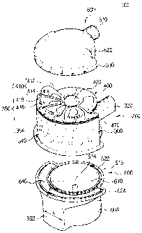
[0016] FIG. 1 is a perspective view of a cyclone vessel
dust collector according to at least one embodiment of the
present invention;
4d
CA 02498156 2005-02-24
[0017] FIG. 2 is an exploded perspective view of the cyclone vessel dust
collector shown in FIG 1;
[0018] FIG. 3 is a schematic view showing the body unit of the cyclone vessel
dust collector shown in FIG. 1;
[0019] FIG. 4 is a schematic view showing the inlet flow passage of the
cyclone
vessel dust collector shown in FIG. 1;
[0020] FIG. 5 is a perspective view showing the filter unit of the cyclone
vessel
dust collector shown in FIG. 1;
[0021] FIG. 6 is an exploded perspective view showing the inlet/outlet unit of
the cvclone vessel dust collector shown in FIG 2;
[0022] FIG. 7 is a top plan view of the inlet/outlet unit shown in FIG 6;
[0023] FIG. 8 is a bottom view of the inlet/outlet unit shown in FIG. 6;
[0024] FIG. 9 is a top plan view of the dirt collection bin shown in FIG. 2;
[0025] FIG. 10 is a cross-sectional view taken along the line 10-10of FIG 9;
[0026] FIG. 11 is a top plan view of the cyclone vessel dust collector shown
in
FIG l ;
[0027] FIG. 12 is a cross-sectional view taken along the line 12-12 of FIG. 1;
[0028] FIG. 13 is a perspective view showing an embodiment of the inventive
vacuum cleaner;
[0029] FIG 14 is a cross-sectional view taken along the line 14-14of FIG 13;
and
[0030] FIG. 15 is a perspective view for describing an operation for
separating
the dirt collection bin from the vacuum cleaner of FIG 13.
CA 02498156 2007-09-06
30235-41
DETAILED DESCRIPTION OF EMBODIMENTS
[0031] Certain embodiments of the present invention will
be described in greater detail with reference to the
accompanying drawings.
[0032] In the following description, drawing reference
numerals are used for the same elements even different
drawings. The embodiments described herein are only
examples and are not intended to limiting the invention
disclosed herein. Rather, the invention disclosed herein is
defined by set forth in the appurtenant claims. Also, well-
known functions or constructions are not described in detail
since they would obscure the invention in unnecessary
detail.
[0033] FIGS. 1 to 3 are perspective and exploded
perspective views showing an embodiment of the inventive
cyclone vessel dust collector. As shown in FIG. 1 and
FIG. 2, the cyclone vessel dust collector 100 of the present
embodiment comprises a cyclone vessel main-body 200, a dirt
collection bin 600 below the main body 200 and a cover 500
over the main body 200.
[0034] As shown in FIG. 2 and FIG. 3, the cyclone vessel
main-body 200 includes a primary cyclone vessel unit 310
(See FIG. 3), and multiple secondary cyclone vessel
units 350 (See FIG. 2).
[0035] A cover 500 is assembled to the top of the cyclone
vessel main-body 200 (See FIG. 2) and a dirt collection
bin 600 is assembled to the bottom of the cyclone vessel
main-body 200 (See FIG. 2). In addition, the cyclone vessel
6
CA 02498156 2007-09-06
30235-41
main-body 200 comprises an external wall (i.e., the outer
circumference) which consists of a first wall 311 with a
first radius and a second wall 340 with a second radius
greater than that of the first wall 311, such that the
external wall comprised of the first wall 311 and the second
wall 340 provide a non-uniform external wall with a first
6a
CA 02498156 2005-02-24
section (311) of a first radius and a second section (340) with a second,
greater
radius.
[0036] Referring to FIGS. 2 and 3, the primary cyclone vessel unit 310 is
enclosed in a cyclone vessel body unit 300. The body unit 300 has a first
inlet
330, a first outlet 320, a filter unit 314, and a first chamber 312. As can be
seen in
FIG. 4, which provides an isolated view of the first inlet 330, the first
inlet 330 has
a straight section 330-1, the terminal end of which 330-2 opens into a curved
section 330-4 from which the air flowing therein is helically curved along the
inner
surface of the first wall 311. As can be seen from FIC-L 4, the front end 330-
5 of
the first inlet 330 takes the form of a substantially rectangular cross-
section with a
domed top side. From the terminal end 330-2 of the first inlet 330, the cross-
sectional area of the first inlet 330 gradually decreases and turns along a
radius
substantially equal to the inner surface of the first wa11311. A substantially
cylindrically-shaped first outlet 320 is located at the center of a first
chamber 312,
which is a space formed by the first wall 311.
[0037] Referring to FIGS. 4, 5 and 12, a filter unit 314 is installed at the
bottom
of the first outlet 320. Air drawn into the first inlet 330 rotates or curls
around the
inner surface of the first wall 311 and produces a cyclonic wind, thereby
causing
dust in the air to experience a centrifugal force that separates suspended
dust
partices within the first chamber 312. The cyclonic-flowing air is drawn
through
the filter unit 314, travels vertically or upwardy is then discharged from the
first
outlet 320 of the filter unit 314.
[0038] As can be seen in FIG. 5, the filter unit 314 has a filter body 319 and
a
downwardly tapered and sloping anti-backflow member 3161ocated at the bottom
7
CA 02498156 2005-02-24
of the filter body 319. As can be seen in more detail from FIG 5, numerous
small
holes "h" extend through the filter body 319 wall. A "L" shaped locking groove
315 at the top of the filter body 319 is sized and shaped to accept a
complementary
and mating locking projection (not shown) formed on the first outlet 320 in
the
circumferential direction.
[0039] The anti-backflow member 316 is preferably integrally molded with the
filter body 319 although at least one alternate embodiment uses an anti-back
flow
member 316 that is separately molded and sized, shaped and arranged to engage
the filter body 319. As shown in FIG. 5, part of the anti-backflow member 316
has a downwardly inclined part 317, ends of which form a cutoff part 318. The
anti-backflow member 316 is substantially "C-shaped" when it is viewed from
the
top.
[0040] Many dust particles are removed from the cyclonic wind in the first
chamber 312 by centrifugal force. Larger particles that are not separated by
centrifugal force are filtered when the air that carries them passes through
the fine
holes "h" of the filter body 319.
[00411 Referring again to FIG. 2, several cone-shaped secondary cyclone vessel
units 350 are arranged to surround almost half of the external wall of the
primary
cyclone vessel unit 310 (see FIG. 2). Each of the secondary cyclone vessel
units
350 comprises a second inlet 410, a second outlet 416, and a second cyclone
vessel
body 354. As can be seen in the figure, the cross-section of each of the cone-
shaped second cyclone vessel bodies 354 decreases as approaches its lower end.
[0042] As shown in FIG. 6, FIG 7 and FIG. 12, each of the second inlets 410 of
a secondary cyclone vessel unit 350 has a substantially linear part 412 that
extends
8
CA 02498156 2005-02-24
from the top of the filter unit 314. The linear part 412 flows into a curved
part
414 by which air flowing into the second inlet 410 changes its direction as it
is
turned downwardly to flow through the curved second part 414 into a
corresponding second cyclone vessel body 354, as shown in FIG. 2.
[0043] Each of the second outlets 416 of a secondary cyclone vessel unit 350
is
formed at the center of the curved part 414 of a corresponding second inlet
410.
A plate 418 is provided at the center of each of the second outlets 416 to
stabilize
the discharged air.
[0044] The second inlets 410 and the second outlets 416 of each of the cone-
shaped second cyclone vessel bodies 354 are integrally formed with each other
on
an inlet/outlet unit 400. The inlet/outlet unit 400 consists of an
inlet/outlet
member 430 and a gasket member 470.
[0045] By arranging the several secondary cyclone vessel units 350 around the
outer circumference of the primary cyclone vessel unit 310, additional
cyclonic
filtration stages can be added while keeping the height of the cyclone vessel
dust
collector 100 minimized. With the foregoing in mind, those of ordinary skill
in
the art will recognize that if the cyclone vessel main-body 200 comprises a
first
wal1311 with a first radius and a second wall 340 with a second radius larger
than
that of the first wall 311, thus forming a non-uniform contour, cyclonic dust
collection efficiency can be enhanced and the entire volume for installing
such a
cyclone vessel dust collector can be saved when it is installed in a vacuum
cleaner.
[0046] Referring again to FIG. 3, the body unit 300 comprises a primary
cyclone vessel unit 310 and plural second cyclone vessel bodies 354, which, in
the
preferred embodiment, are integrally formed with each other by injection
molding
9
CA 02498156 2005-02-24
techniques, well-known to those of ordinary skill in the art of injection
molding.
Those of ordinary skill in the injection molding art will recognize however
that the
body unit 300 can also be assembled from two or more separate and
independently
injection-molded parts which are then assembled together after being molded.
[0047] As can be seen in FIG. 3, the body unit 300 comprises a first chamber
321 having an exterior wall that is defined substantially by the first
wa11311. A
second chamber 342 that receives the second cyclone vessel bodies is
substantially
defined by the second wall 340. The first chamber 312 and the second chamber
342 are partitioned into separate spaces by the first wall 311. With this
arrangement, it is possible to prevent fine dusts separated in the secondary
cyclone
vessel units 350 from flowing into the first chamber 312 of the primary
cyclone
vessel unit 310 and then into the secondary cyclone vessel units 350 again.
[0048] Referring to FIGS. 6 to 8 and FIG. 12, the inletloutlet unit 400 is
formed
by assembling two separate members, i.e., an inlet/outlet member 430 and a
gasket
member 470. As can be seen from FIG. 8 and FIG 12, the second inlets 410
form a complete inlet flow passage when they are assembled with a gasket
member
470 at the bottom surface of the inlet/outlet member 430. That is, air flowing
from the first outlet 330 of the primary cyclone vessel unit 310 runs into an
air
receiving section 420, passes through opened sections 415 of the linear parts
212
of the second inlets 410, turns along closed sections 415 of the linear parts
212
covered by the gasket member 470, and then enters the second cyclone vessel
bodies 354. (See FIG. 2, FIG. 6 and FIG. 12.)
[0049] Referring to FIGS. 6, 7 and 12, the second outlets 416 are provided at
the centers of the curved parts 414 of the second inlets 410, respectively, in
which
CA 02498156 2005-02-24
a pipe "P" is provided in each of the second outlets in such a way that the
pipe
member P extends above and below the inlet/outlet member 430 as shown in FIG.
12. The gasket member 470 is interposed between the inlet/outlet member 430
and the body unit 300, thereby serving to seal the gap between the
inlet/outlet
member 430 and the body unit 300 beyond finishing the flow passages of the
second inlets 416 as described above.
[0050] Referring to FIGS. 2, 9, 10 and 12,a dirt collection bin 600 comprises
a
first dust collection chamber 610 and a second dust collection chamber 640.
The
first dust collection chamber 610 is cylindrical. As best shown in FIG. 2 and
FIG.
9, the second dust collection chamber 640 is a partial annulus, formed to
surround
a part of the outer circumference of the first dust collection chamber 610. It
is
connected to a side of the first dust collection chamber 610. The inner
circuinference of the second dust collection chamber 640 is defined by a third
wall
615 that also defines the circumference of the first dust collection chamber
610.
The outer circumference of the second dust collection chamber 640 is
determined
by a fourth wall 664 with a diameter larger than that of the third wall 615.
[0051] As best seen in FIG. 2, the fourth wal1664 includes a protrusion or
raised part 662, which extends outwardly and away from the dust collection bin
600 and which can be used as a handle for a user. The raised part 662 has a
width
L that is substantially narrower than the span of a hand of an ordinary adult
thus
allowing the dust collection bin 600 to be easily grasped.
[0052] As can be seen in FIG.. 12, when the dirt collection bin 600 is
installed
to the bottom of the body unit 300, the first dust collection chamber 610 is
in fluid
communication with the first chamber 312. The second dust collection chamber
11
CA 02498156 2005-02-24
640 is communicated with the second chamber 342. As can be seen in FIG. 10,
which is a sectional view of the dust collection bin 600 as shown in FIG. 9
but
taken through section lines 10-10, the top of the dirt collection bin 600 is
formed
with grooves 622 that are sized and shaped to accept a gasket or sealing
member
625, the location of which is shown in FIG. 9. When a gasket or sealing is
inserted
into the grooves 622 and the dust collection bin 600 is attached to the body
unit
300, the gasket/sealing member 625 provides a substantially air-tight seal.
(See FIG
12.)
[00531 As can be seen in FIGs. 2, 9, 10 and 12, the first dust collection
chamber
610 is provided with a central shaft 614 and a separation membrane 617. The
central shaft 614 provides a rotation center for the cyclonic air currents
that can
develop in the dust first dust collection chamber 610. The separation membrane
617, however, serves to suppress or impede cyclonic air rotation or turning at
the
bottom of the first dust collection chamber 610, so as to prevent or control
dust
particles that lie at the bottom of the chamber 610 from being lifted by
cyclonic air
currents.
[0054J Referring now to FIGS. 2, 11 and 12, a cover 500 is mounted on the top
of the cyclone vessel main-body 200 to enclose the top of the input/output
unit 400.
A pipe-shaped outlet 510 is formed to project sideways on a "side" of the
cover
500 as shown in FIG. 11. Clean air escaping from the second outlets 416 is
collected in the cover chamber 550 (See FIG. 12.) of the cover 500 and
discharged
through the cover outlet 510. As can be seen in FIGs. 2 and 11, the outer
circumference of the cover 500 that is defined by the sixth wa 530, is
segmented or
"divided" by a fifth wall 520 having a radius less than the sixth wall 530.
12
CA 02498156 2005-02-24
[0055] Operation of the cyclone vessel dust collector 100 as described above
is
hereinafter described in detail with respect to the various figures.
[0056] Referring to FICx 12, the surrounding air, which enters the first inlet
330
with dirt, dusts or the like contained in the air, flows into the first
chamber 312 of
the primary cyclone vessel unit 310 while turning along a semicircular passage
provided by the curved section 330-4 that begins at the terminal end 330-2 of
the
straight section 330-1 of the first inlet 330, as shown in FIG. 5. Heavy dirt,
coarse
dusts or the like are dropped downwardly from the inflow air by centrifugal
force
and finally dropped into the bottom of the first dust collection chamber 610
communicated with the first chamber 312. The air, from which dirt, dusts,
etc.,
are removed to some extent, passes through the fine holes h of the filter unit
314,
whereby the dusts, dirt, etc. coarser than the fine holes are filtered again.
[0057] The anti-backflow member 316 of the filter unit 314 shown in FIG. 5
and FIG. 12, acts to hinder dirt particles lying at the bottom of the first
dust
collection chamber 610 from being lifted by cyclonic air streams.
[0058] Air that passes through the filter unit 314, runs into the air
receiving
section 420 and disperses in all directions and then flows into the second
inlets 410.
Air that flows into the second inlets is cyclonically rotated again while
passing the
linear parts 412 and the curved parts 414 of the second inlets 410 causing
fine
dusts to drop into the second dust collection chamber 640. Air that is
filtered in
this manner flows through the second outlets 416 of the secondary cyclone
vessel
units 350 and into the cover chamber 550 from where it is discharged through
the
cover outlet 510.
[0059] Because the cyclone vessel dust collector 100 as described above is
13
CA 02498156 2005-02-24
arranged in such a way that the secondary cyclone vessel units 350 surround
the
outer circumference (external wall) of the primary cyclone vessel unit 310,
multiple cyclonic flows can be created while keeping the height of the cyclone
dust
collector 100 minimized.
[0060] FIG. 13 is a perspective view showing an embodiment of a vacuum
cleaner 800, in which the aforementioned cyclone vessel dust collector 100 is
used.
FIG. 14 is a cross-sectional view of the vacuum cleaner 800 taken along the
section
line 14-14 of FIG. 13. FIG. 15 shows how the dirt collection bin is installed
into
and removed from the vacuum cleaner 800.
[0061] The vacuum cleaner 800 shown in FIG. 13 and 15 is commonly known
as an "upright" cleaner. However, the present invention is not limited to use
in
such upright vacuum cleaners and those of ordinary skill in the art will
recognize
that cyclone dust collector 100 can be applied to other types of cleaners such
as
canister cleaner.
[0062] Referring to FIGS. 13 to 15, the vacuum cleaner 800 comprises a brush
assembly 820, a vacuum cleaner body 830, the cyclone vessel dust collector
100,
and a cleaner frame 810. As shown in FIG. 13, the cyclone vessel dust
collector
100 is installed in the vacuum cleaner body 830. That is, as can be seen from
FIG.
14, the fifth wall (FIG. 2) of the cover 500 of the cyclone vessel dust
collector 100,
the first wall 311 (FIG. 3) of the cyclone vessel main-body 200 and the third
wall
615 of the first dust collection chamber of the dirt collection bin 600 (FIG.
9) are
partially inserted into the vacuum cleaner body 830, and the sixth wall 530 of
the
dirt collection bin 600, the second wall 340 (FIG. 3) of the cyclone vessel
main-
body 200, and the fourth wall 664 (FIG. 9) of the second dust collection
chamber
14
CA 02498156 2005-02-24
640 of the dirt collection chamber 600 outwardly project.
[00631 Referring to FIG. 14, a projection 355 extending from the lower end of
the body unit 300 of the dust collector 100 is substantially flush with the
outer
circumference of the vacuum cleaner body 630. Accordingly, it is possible to
reduce the size of the vacuum cleaner body 830 while increasing the dust
collection capacity of the cyclone vessel dust collector 100. In operation,
the first
inlet 330 of the cyclone vessel dust collector 100 is inserted into a first
opening
837 of the vacuum cleaner body 830 and in fluid communication with a suction
port (not shown) formed in the brush assembly 820 to draw in surrounding air.
In addition, the cover outlet 510 is inserted into a second opening 835 of the
vacuum cleaner body 830, connected to a vacuum source (not shown) of the
cleaner and in fluid communication with an air discharge port (not shown) of
the
vacuum cleaner. Because the other components are same with those generally
known in the art, the description thereof is omitted.
[0064] With the vacuum cleaner 800 constructed in this manner, when the
vacuum source (not shown) provided in the vacuum cleaner body 830 is operated,
surrounding air is introduced into a suction port (not shown) of the brush
assembly
820 and then into the first inlet 330 connected to the first opening 837 of
the
vacuum cleaner body 830. As the drawn-in air passes the primary cyclone vessel
unit 310 (FIG. 3), coarse dusts or dirt are removed from the air and the air
is
introduced into the secondary cyclone vessel units 350 through the first
outlet 320.
The secondary cyclone vessel units 350 remove fine dusts or the like and then
discharges purified air through the second outlets 416 and the cover outlet
510 to
the discharge port (not shown) of the vacuum cleaner. The dusts or dirt
separated
CA 02498156 2005-02-24
in this manner are accumulated in the first dust collection chamber 610 and
the
second collection chamber 640 of the dirt collection bin 600. Therefore, the
user
can grip and simply separate the raised part 662 of the dirt collection bin
600 and
dump the dirt collected in the first dust collection chamber 610 and the dusts
in the
second dust collection chamber 640 at the same time.
[0065] While the preferred embodiments of the present invention have been
shown and described with reference to the representative embodiments thereof
in
order to exemplify the principle of the present invention, the present
invention is
not limited to the embodiments. It will be understood that various
modifications
and changes can be made by those skilled in the art without departing from the
spirit and scope of the invention as defined by the appended claims.
Therefore, it
shall be considered that such modifications, changes and equivalents thereof
are all
included within the scope of the present invention.
16