Note: Descriptions are shown in the official language in which they were submitted.
CA 02498412 2005-03-09
SF-973
1
DESCRIPTION
Apparatus and Method for Identifying Concentration of Urea and
Apparatus and Method for Reducing Exhaust Gas of Car using the
Same
TECHNICAL FIELD
The present invention relates to an apparatus and method
for identifying the concentration of the urea of a urea solution,
and an apparatus and method for reducing the exhaust gas of a
car using the apparatus and method.
BACKGROUND ART
Conventionally, the exhaust gas of a car contains pollutants
such as unburned hydrocarbon (HC), an NOx gas and an SOx gas.
In order to reduce the pollutants, therefore, Sulfur (S) in a
gasoline or light oil is removed for the Sox or unburned Hydrocarbon
(HC) is burned by a catalyst, for example.
More specifically, as shown in Fig. 13, a car system 100
takes air in through an automatic element (filter) 102 and feeds
the air into an engine 106 through an air flow sensor 104 . Moreover,
the car system 100 feeds a fuel in a fuel tank 108 into the engine
106 through a fuel pump 110.
Based on the result of the detection of an A/F sensor 112,
the injection of the fuel in the engine 106 is controlled by a
CA 02498412 2005-03-09
SF-97;3
2
fuel inj ection control device 114 in order to have a predetermined
theoretical air fuel ratio.
For an exhaust gas fed from the engine 106, hydrocarbon
(HC) in the exhaust gas is burned by a catalytic device 116 and
is then discharged as the exhaust gas through an oxygen
concentration sensor 118.
In consideration of the influence of the NOx in the exhaust
gas on an environment, recently, there has been proposed a method
of supplying a urea solution to the catalytic device 116, thereby
reducing the NOx to be non-toxic as an N2 gas in order to decrease
the NOx in the exhaust gas discharged from the fuel of a car,
for example, a gasoline or light oil.
More specifically, as shown in Fig. 13, the car system 100
has such a structure as to supply a urea solution to the upstream
side of the catalytic device 116 through a urea solution supplying
mechanism 130 constituted by a urea solution tank 132 for storing
a urea solution, a urea pump 134 and a urea spraying device 136
for spraying the urea solution fed from the urea pump 134 onto
the upstream side of the catalytic device 116.
In such a car system, it is suitable that 32 . 5 ~ by weight
of urea and 67.5° by weight of H-~0 should be set in order to
efficiently generate a reducing reaction at the upstream side
of the catalytic device 116 without causing the urea solution
to cake, for example.
CA 02498412 2005-03-09
SF-973
3
For this reason, conventionally, NOx sensors 140 and 142
have been provided at the upstream and downstream sides of the
catalytic device 116 respectively to measure the concentration
of NOx in order to decide whether or not the concentration of
a urea sprayed onto the upstream side of the catalytic device
116 is constant.
However, the NOx sensors 140 and 142 measure the
concentration of the urea as a result of the reducing rate of
NOx. For this reason, it is impossible to previously identify
the concentration of the urea which is contained in the urea
solution tank 132 or is sprayed. Moreover, the NOx sensors 140
and 142 do not have very high sensitivities.
The present inventors have already proposed a fluid
identifying method in Japanese Laid-Open Patent Publication No.
11-153561 (particularly see paragraphs [0042] to [0049]). This
method is to cause a heating member to generate heat by carrying
electricity, heating a temperature detector through the heat
generation,thermallyinfluencingaheattransferfromthe heating
member to the temperature detector through a fluid to be identified,
and distinguishing the type of the identified fluid based on an
electrical output corresponding to the electric resistance of
the temperature detector, thereby periodically carrying the
electricity to the heating member,
In the fluid identifying method, however, it is necessary
CA 02498412 2005-03-09
SF-973
9
to periodically carry the electricity to the heating member ( in
a multipulse) . For this reason, a long time is required for the
identification so that it is hard to identify a fluid
instantaneously. In this method, moreover, it is possible to
identify a fluid based on a central value for substances having
very different properties such as water, air and oil. However,
it is hard to identify the concentration of the urea of the urea
solution accurately and immediately.
In consideration of such circumstances, it is an object
of the present invention to provide an apparatus and method for
identifying the concentration of the urea of a urea solution which
can identify the concentration of the urea of the urea solution
accurately and immediately.
Moreover, it is an obj ect of the present invention to provide
an apparatus and method for reducing the exhaust gas of a car
using the apparatus and method for identifying the concentration
of the urea of a urea solution which can efficiently reduce the
exhaust gas and can enhance a mileage.
DISCLOSURE OF THE INVENTION
The present invention has been made to solve the problems
and to attain the obj ects in the prior art described above, and
provides an apparatus for identifying a concentration of a urea
of a urea solution, comprising:
CA 02498412 2005-03-09
SF-973
a urea concentration identifying chamber for causing an
identified urea solution introduced into a urea concentration
identifying apparatus body to stay temporarily;
a urea concentration identifying sensor heater provided
5 in the urea concentration identifying chamber; and
a liquid temperature sensor provided in the urea
concentration identifying chamber apart from the urea
concentration identifying sensor heater at a constant interval;
theurea concentrationidentifyingsensor heaterincluding
a heater and an identifying liquid temperature sensor provided
in the vicinity of the heater, and
theapparatusfurther comprising anidentification control
portion for applying a pulse voltage to the urea concentration
identifying sensor heater for a predetermined time, heating the
identified urea solution staying temporarily in the urea
concentration identifying chamber by the heater and identifying
the concentration of the urea with a voltage output difference
VO corresponding to a temperature difference between an initial
temperature and a peak temperature in the identifying liquid
temperature sensor.
Moreover, the present invention provides a method for
identifying a concentration of a urea of a urea solution,
comprising the steps of:
applying a pulse voltage for a predetermined time to a urea
CA 02498412 2005-03-09
SF-973
G
concentration identifying sensor heater including a heater and
an identifying liquid temperature sensor provided in the vicinity
of the heater;
heating an identified urea solution by the heater; and
identifying the concentration of the urea with a voltage
output difference VO corresponding to a temperature difference
between an initial temperature and a peak temperature in the
identifying liquid temperature sensor.
By such a structure, it is sufficient that the pulse voltage
is applied for the predetermined time. Consequently, it is
possible to identify the concentration of the urea of the urea
solution accurately and immediately through heating for a short
time.
More specifically, there are utilized the correlation of
the kinetic viscosity of the urea solution with a sensor output,
a natural convection, and furthermore, an applied voltage having
one pulse. Therefore, it is possible to identify the
concentration of the urea of the urea solution accurately and
immediately.
Furthermore,thepresentinventionischaracterizedinthat
the voltage output difference VO is equal to a voltage difference
between an average initial voltage V1 obtained by sampling an
initial voltage before application of the pulse voltage at a
predetermined number of times and an average peak voltage V2
CA 02498412 2005-03-09
SF-973
7
obtained by sampling a peak voltage after the application of the
pulse voltage at a predetermined number of times, that is,
VO = V2 - V1.
By such a structure, it is possible to accurately obtain
the voltage output difference VO based on the average value of
the sampling at the predetermined number of times for the applied
voltage having one pulse. Consequently, it is possible to
identify the concentration of the urea of the urea solution
accurately and immediately.
In addition, the present invention provides the apparatus
for identifying a concentration of a urea of a urea solution,
wherein the identification control portion identifies a
concentration of a urea of a urea solution with the voltage output
difference VO obtained for the identified urea solution based
on calibration curve data to be a correlation of a voltage output
difference with a temperature for a predetermined reference urea
solution prestored in the identification control portion.
Moreover, the present invention provides the method for
identifying a concentration of a urea of a urea solution, wherein
a concentration of a urea of a urea solution is identified with
the voltage output difference VO obtained for the identified urea
solution based on calibration curve data to be a correlation of
a voltage output difference with a temperature for a predetermined
reference urea solution which is prestored.
CA 02498412 2005-03-09
SF-97:3
8
By such a structure, the concentration of the urea of the
urea solution is identified with the voltage output difference
VO obtained for the identified urea solution based on the
calibration curve data, which is correlated with the voltage
output difference with the temperature for the predetermined
reference urea solution which is prestored. Therefore, it is
possible to identify the concentration of the urea of the urea
solution more accurately and immediately.
Furthermore, the present invention provides the apparatus
for identifying a concentration of a urea of a urea solution,
wherein the identification control portion correlates a liquid
type voltage output Vout for the voltage output difference VO
at a measuring temperature of the identified urea solution with
an output voltage for a voltage output difference at a measuring
temperaturefor a predeterminedthreshold referenceureasolution
and thus carries out a correction.
In addition, the present invention provides the method for
identifying a concentration of a urea of a urea solution, wherein
a liquid type voltage output Vout for the voltage output difference
VO at a measuring temperature of the identified urea solution
is correlated with an output voltage for a voltage output
difference at a measuring temperature for a predetermined
threshold reference urea solution and is thus corrected.
By such a structure, the liquid type voltage output Vout
CA 02498412 2005-03-09
SF-973
9
for the voltage output difference VO at the measuring temperature
of the identified urea solution is correlated with the output
voltage for the voltage output difference at the measuring
temperature for the predetermined threshold reference urea
solution and is thus corrected. Consequently, it is possible
to eliminate the influence of the temperature on the voltage output
difference V0, thereby giving the correlation of the liquid type
voltage output Vout with the properties of the urea solution more
accurately. Thus, it is possible to identify the concentration
of the urea of the urea solution further accurately and
immediately.
Moreover, the present invention is characterized in that
the urea concentration identifying sensor heater is a laminated
urea concentration identifying sensor heater in which a heater
and an identi fying liquid temperature sensor are laminated through
an insulating layer.
By such a structure, a mechanism portion for carrying out
a mechanical operation is not present. Therefore, an operation
failure is not caused by a deterioration with the passage of time,
foreign matters in the urea solution or the like. Thus, it is
possible to identify the concentration of the urea of the urea
solution accurately and immediately.
In addition, the sensor portion can be constituted to be
very small-sized. Consequently, it is possible to identify the
CA 02498412 2005-03-09
SF-97
l.0
concentration of the urea of the urea solution accurately with
a very excellent thermal responsiveness.
Furthermore,the presentinventionischaracterizedinthat
the heater and the identifying liquid temperature sensor in the
urea concentration identifying sensor heater are constituted to
come in contact with the identified urea solution through a
metallic fin, respectively.
By such a structure, the heater and the identifying liquid
temperature sensor in the urea concentration identifying sensor
heater do not directly come in contact with the identified urea
solution. Therefore, an operation failure is not caused by a
deterioration with the passage of time, foreign matters in the
urea solution or the like. Thus, it is possible to identify the
concentration of the urea of the urea solution accurately and
immediately.
Moreover, the present invention is characterized in that
the liquid temperature sensor is constituted to come in contact
with the identified urea solution through the metallic fin.
By such a structure, the liquid temperature sensor does
~0 not directly come in contact with the identified urea solution.
Therefore, an operation failure is not caused by a deterioration
with the passage of time, foreign matters in the urea solution
or the like. Thus, it is possible to identify the concentration
of the urea of the urea solution accurately and immediately.
CA 02498412 2005-03-09
SF-97:3
11
In addition, the present invention provides an apparatus
for reducing an exhaust gas of a car, comprising
a urea solution supplying mechanism for supplying a urea
solution to an upstream side of a catalytic device,
wherein the urea solution supplying mechanism is
constituted by a urea solution tank for storing the urea solution,
a urea pump and a urea spraying device for spraying the urea solution
fed from the urea pump to the upstream side of the catalytic device,
and
any of the apparatuses for identifying a concentration of
a urea of a urea solution described above is provided in the urea
tank or on an upstream side or a downstream side of the urea pump.
Furthermore, the present invention provides a method for
reducing an exhaust gas of a car, comprising the steps of supplying
25 a urea solution to an upstream side of a catalytic device through
a urea solution supplying mechanism constituted by a urea solution
tank for storing the urea solution, a urea pump and a urea spraying
device for spraying the urea solution fed from the urea pump onto
the upstream side of the catalytic device, and
identifying a concentration of a urea of the urea solution
in the urea tank or on an upstream side or a downstream side of
the urea pump by using any of the methods for identifying a
concentration of a urea of a urea solution described above.
By such a structure, it enables to accurately and immediately
CA 02498412 2005-03-09
SF-9 r3
12
decide the amount of urea concentration, for example, whether
or not 32.50 by weight of urea and 67.50 by weight of HBO are
set in order to efficiently generate a reducing reaction at the
upstream side of the catalytic device 116 without causing the
urea solution to cake.
Accordingly, the urea of the urea solution in the urea tank
can be maintained to have a predetermined concentration.
Consequently, NOx in the exhaust gas can be greatly decreased
by a reduction.
BRIEF DESCRIPTION OF THE DRAWINGS
Fig. 1 is a schematic top view showing an example of an
apparatus for identifying the concentration of the urea of a urea
solution according to the present invention,
Fig. 2 is a sectional view taken along an A - A line in
Fig. 1,
Fig. 3 is a right side view of Fig. 1,
Fig. 4 is a left side view of Fig. l,
Fig. 5 is a partially enlarged sectional view showing a
state in which a urea concentration identifying sensor is attached
in Fig. 2,
Fig. 6 is a sectional view showing the urea concentration
identifying sensor,
Fig. 7 is a partially enlarged exploded perspective view
CA 02498412 2005-03-09
SF-973
1:3
showing a state in which the thin film chip portions of the urea
concentration identifying sensor are laminated,
Fig. 8 is a schematic diagram showing the structure of a
circuit according to the example of the apparatus for identifying
the concentration of the urea of a urea solution according to
the present invention,
Fig. 9 is a graph showing a relationship between a time
and a voltage, illustrating a method for identifying the
concentration of a urea using the apparatus for identifying the
concentration of the urea of a urea solution according to the
present invention,
Fig . 10 is a graph showing a calibration curve, illustrating
the method for identifying the concentration of a urea using the
apparatus for identifying the concentration of the urea of a urea
solution according to the present invention,
Fig. 11 is a graph showing an output correcting method in
the method for identifying the concentration of a urea using the
apparatus for identifying the concentration of the urea of a urea
solution according to the present invention,
Fig. 12 is the same schematic diagram as Fig. 13,
illustrating an example in which an apparatus 10 for identifying
the concentration of the urea of a urea solution according to
the present invention is applied to a car system, and
Fig. 13 is a schematic diagram showing a conventional car
CA 02498412 2005-03-09
SF-973
l.4
system.
BEST MODE FOR CARRYING OUT THE INVENTION
Embodiments (examples) of the present invention will be
described below in more detail with reference to the drawings.
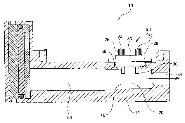
As shown in Figs. 1 and 2, an apparatus 10 for identifying
the concentration of the urea of a urea solution according to
the present invention comprises a urea concentration identifying
apparatus body 12, and a first passage 14 and a second passage
16 which are formed in the urea concentration identifying
apparatus body 12.
As shown in an arrow of Fig. 1, aureasolutiontobe identified
which flows from a urea solution inlet 18 into the first passage
14 passes through an intermediate chamber 56. Then, the
identified ureasolution passes throughthe intermediatechamber
56, and thereafter, enters the second passage 16 to temporarily
stay in a urea concentration identifying chamber 20.
The urea concentration identifying chamber 20 is provided
with an opening portion 22 for a urea concentration identifying
sensor taking the shape of an almost truck in an upper part thereof .
As shown in Fig. 2, a urea concentration identifying sensor
24 is attached to the opening portion 22 for the urea concentration
identifying sensor.
As shown in Fig. 5, the urea concentration identifying sensor
CA 02498412 2005-03-09
SF-9'7:3
24 includes a urea concentration identifying sensor heater 25
and a liquid temperature sensor 28 provided apart from the urea
concentrationidentifyingsensorheater25ata constantinterval.
Then, the urea concentration identifying sensor heater 25 and
5 the liquid temperature sensor 28 are formed integrally by a mold
resin 30.
As shown in Fig. 6, moreover, the urea concentration
identifying sensor heater 25 includes a lead electrode 32 and
a thin film chip portion 34. Moreover, the urea concentration
10 identifying sensor heater 25 is provided with a metallic fin 36
protruded into the urea concentration identifying chamber 20 to
directly come in contact with the identified urea solution through
the opening portion 22 for the urea concentration identifying
sensor from the mold resin 30. Then, the lead electrode 32, the
15 thin film chip portion 34 and the fin 36 are mutually connected
electrically through a bonding wire 38.
On the other hand, the liquid temperatures sensor 28 also
has the same structure as that of the urea concentration
identifying sensor heater 25, and includes the lead electrode
32, the thin film chip portion 34, the fin 36 and the bonding
wire 38 respectively.
As shown in Fig. 7, the thin film chip portion 34 is
constituted by a thin film=shaped chip in which a substrate 40
formed of Al=O~, a temperature sensor (temperature detector) 42
CA 02498412 2005-03-09
SF-973
16
formed of PT, an interlayer insulating film 44 formed of SiO~,
a heater (heating member) 46 formed of TaSiO~, a heating member
electrode 48 formed of Ni, a protective film 50 formed of SiO~,
and an electrode pad 52 formed of Ti/Au are provided in order,
for example.
While the thin film chip portion 34 of the liquid temperature
sensor 28 also has the same structure, it is so constituted as
not to cause the heater (heating member) 46 to act but to cause
only the temperature sensor (temperature detector) 42 to act.
After the liquid type of the identified urea solution is
identified by the urea concentration identifying sensor 24, the
identified ureasolutionisdischargedfromtheureaconcentration
identifying chamber 20 to an outside through a urea solution
discharge port 54.
In Figs . 1 and 2, moreover, a circuit board member connected
to the urea concentration identifying sensor 24 and a lid member
for covering the circuit board member are not shown.
The apparatus 10 for identifying the concentration of the
urea of a urea solution according to the present invention has
the structure of a circuit shown in Fig. 8.
In Fig. 8, an identifying liquid temperature sensor 26 of
the urea concentration identifying sensor heater 25 and the liquid
temperaturesensor28intheurea concentrationidentifyingsensor
24 are connected to each other through two resistors 64 and 66,
CA 02498412 2005-03-09
SF-973
17
thereby constituting a bridge circuit 68 . The output of the bridge
circuit 68 is connected to the input of an amplifier 70, and the
output of the amplifier 70 is connected to the input of a computer
72 constituting an identification control portion.
Moreover, the applied voltage of a heater 74 of the urea
concentration identifying sensor heater 25 is controlled under
the control of the computer 72.
In the apparatus 10 for identifying the concentration of
the urea of a urea solution which has such a structure, thus,
the concentration of the urea of the urea solution is identified
in the following manner.
First of all, the identified urea solution is caused to
flow from the urea solution inlet 18 of the first passage 14 of
the apparatus 10 for identifying the concentration of the urea
of a urea solution and is caused to stay temporarily in the urea
concentration identifying chamber 20 of the second passage 16.
As shown in Figs. 8 and 9, a pulse voltage P is applied
to the heater 74 of the urea concentration identifying sensor
heater 25 under the control of the computer 72 for a predetermined
time, that is, four seconds in the present example, and a change
in the temperature of the analog output of a sensing portion,
that is, the sensor bridge circuit 68 shown in Fig. 8 is measured.
Morespecifically, as shown in Fig. 9, the voltagedifference
of the sensor bridge circuit 68 is sampled at a predetermined
CA 02498412 2005-03-09
SF-9?3
18
number of times, for example, 256 times in the present example
for one second before the pulse voltage P is applied to the heater
74 of the urea concentration identifying sensor heater 25, and
an average value thereof is set to be an average initial Voltage
V1. The value of the average initial voltage V1 corresponds to
the initial temperature of the identifying liquid temperature
sensor 26.
As shown in Fig. 9, the predetermined pulse voltage P, that
is, a Voltage of lOV in the present example is applied to the
heater 74 of the urea concentration identifying sensor heater
25 for four seconds . Subsequently, a value obtained by sampling
a peak voltage at a predetermined number of times, for example,
256 times in the present example for one second after a
predetermined time, for example, 3 seconds in the present example
is set to be an average peak voltage V2. The average peak voltage
V2 corresponds to the peak temperature of the identifying liquid
temperature sensor 26.
A voltage output difference VO is obtained from a Voltage
difference between the average initial voltage Vl and the average
peak voltage V2, that is,
VO = V2 - V1.
By such a method, as shown in Fig. 10, calibration curve
data to be the correlation of a voltage output difference with
a temperature are previously obtained for a predetermined
CA 02498412 2005-03-09
SF-973
19
reference urea solution, that is, 0 ~ by weight of urea, 40°~ by
weight of urea and 20° by weight of urea in the present example,
and are stored in the computer 72 constituting the identification
control portion.
Based on the calibration curve data, a proportional
calculation is carried out in the computer 72 and the concentration
of the urea of the urea solution is identified with the voltage
output difference VO obtained for the identified urea solution.
More specifically, as shown in Fig. 11, a liquid type voltage
output Vout for the voltage output difference VO at a measuring
temperature T of the identified urea solution is correlated with
an output voltage for a voltage output difference at a measuring
temperaturefor a predetermined threshold referenceureasolution
(20 o by weight of urea and 40 o by weight of urea in the present
example) and is thus corrected.
In other words, as shown in Fig. 11(A), a voltage output
difference VO-20 of 20° by weight of urea, a voltage output
difference VO-40 of 40'~ by weight of urea and a voltage output
difference VO-S of the identified urea solution are obtained at
the temperature T based on the calibration curve data.
As shown in Fig. 11 (B) , the liquid type voltage output Vout
of the identified urea solution is obtained by setting the liquid
type output of the threshold reference urea solution, so that
a correlation with the properties of the urea can be acquired.
CA 02498412 2005-03-09
SF-97:3
In this case to have a predetermined voltage, that is, by setting
the liquid type output of 40~ by weight of urea to be 3.5V and
the liquid type output of 20o by weight of urea to be 0.5V in
the present example.
5 The liquid type voltage output Vout of the identified urea
solution is previously compared with data stored in the computer
72 based on the calibration curve data. Consequently, it is
possible to identify the concentration of the urea of the urea
solution accurately and immediately (instantaneously).
10 The method for identifying the concentration of the urea
of a urea solution described above utilizes a natural convection
and a principle in which the kinetic viscosity of the urea and
the sensor output have a correlation.
Fig. 12 is the same schematic diagram as Fig. 13,
15 illustrating an example in which the apparatus 10 for identifying
the concentration of the urea of a urea solution having such a
structure is applied to a car system.
The same components as those in Fig. 13 have the same
reference numerals and detailed description thereof will be
20 omitted.
In a car system 100, the apparatus 10 for identifying the
concentration of the urea of a urea solution is provided in a
urea solution tank 132 or on the upstream side of a urea pump
134.
CA 02498412 2005-03-09
SF-97:3
21
The apparatus 10 for identifying the concentration of the
urea of a urea solution identifies the concentration of the urea
of the urea solution in the urea solution tank 132 or on the upstream
or downstream side of the urea pump 134 (the case of the upstream
side will be described in the present example for convenience
of explanation) and sets the concentration of the urea to be sprayed
onto the upstream side of a catalytic device 116 into a constant
state, for example, 32 . 5 o by weight of urea and 67 . 5 o by weight
of H20 in order to efficiently generate a reducing reaction at
the upstream side of the catalytic device 116 without causing
the urea solution to cake.
Accordingly, the urea of the urea solution in the urea tank
can be maintained to have a predetermined concentration.
Therefore, it is possible to greatly decrease NOx in an exhaust
gas by a reduction.
While the preferred examples of the present invention have
been described above, the present invention is not restricted
thereto but various changes can be made without departing from
the obj ects of the present invention, for example, a pulse voltage
z0 P, the number of sampling operations and the like can be changed
properly.
(Effect of the Invention)
According to the present invention, it is sufficient that
CA 02498412 2005-03-09
SF-9'73
22
a pulse voltage is applied for apredetermined time . Consequently,
it is possible to identify the concentration of the urea of a
urea solution accurately and immediately through heating for a
short time.
More specifically, there are utilized the correlation of
the kinetic viscosity of the urea solution with a sensor output,
a natural convection, and furthermore, an applied voltage having
one pulse. Therefore, it is possible to identify the
concentration of the urea of the urea solution accurately and
immediately.
According to the present invention, moreover, it is possible
to accurately obtain a voltage output difference VO based on the
average value of sampling at a predetermined number of times for
the applied voltage having one pulse. Consequently, it is
possible to identify the concentration of the urea of the urea
solution accurately and immediately.
According to the present invention, furthermore, the
concentration of the urea of the urea solution is identified with
the voltage output difference VO obtained for the identified urea
solution based on calibration curve data to be the correlation
of a voltage output difference with a temperature for a
predetermined reference urea solution which is prestored.
Therefore, it is possible to identify the concentration of the
urea of the urea solution more accurately and immediately.
CA 02498412 2005-03-09
SF-973
23
According to the present invention, moreover, a liquid type
voltage output Vout for the voltage output difference VO at the
measuringtemperature oftheidentified ureasolutioniscorrected
to be correlated with the output voltage for the voltage output
difference at the measuring temperature for a predetermined
threshold reference ureasolution. Consequently, itispossible
to eliminate the influence of the temperature on the voltage output
difference V0, thereby giving the correlation of the liquid type
voltage output Vout with the properties of the urea solution more
accurately. Thus, it is possible to identify the concentration
of the urea of the urea solution further accurately and
immediately.
According to the present invention, furthermore, a
mechanism portion for carrying out a mechanical operation is not
present. Therefore, an operation failure is not caused by a
deterioration with the passage of time, foreign matters in the
urea solution or the like. Thus, it is possible to identify the
concentration of the urea of the urea solution accurately and
immediately.
In addition, the sensor portion can be constituted to be
very small-sized. Consequently, it is possible to identify the
concentration of the urea of the urea solution accurately with
a very excellent thermal responsiveness.
According to the present invention, moreover, the heater
CA 02498412 2005-03-09
SF-973
24
of the urea concentration identifying sensor heater, the
identifying liquid temperature sensor and the liquid temperature
sensor do not directly come in contact with the identified urea
solution. Therefore, an operation failure is not caused by a
deterioration with the passage of time, foreign matters in the
urea solution or the like. Thus, it is possible to identify the
concentration of the urea of the urea solution accurately and
immediately.
According to the present invention, furthermore, it is
possible to accurately and immediately decide whether or not 32 . 5°>
by weight of urea and 6'7.50 by weight of H~0 are set in order
to efficiently generate a reducing reaction at the upstream side
of the catalytic device 116 without causing the urea solution
to cake.
Accordingly, the urea of the urea solution in the urea tank
can be maintained to have a predetermined concentration.
Consequently, the NOx in the exhaust gas can be greatly decreased
by a reduction. Thus, the present invention can produce various
remarkable and peculiar functions and effects, which is very
excellent.