Note: Descriptions are shown in the official language in which they were submitted.
CA 02498516 2005-03-10
WO 2004/024453 PCT/SG2003/000142
-1-
"INK TANK (INKJET INK CARTRIDGE)"
TECFINICAL FIELD
The invention relates generally to an ink cartridge and related methods of
manufacture or use and related assemblies or combinations.
BACKGROUND ART
As used herein the term "ink cartridge" includes a cartridge which of itself
may
incorporate or may be adapted to connect to inkjet printing apparatus or part
thereof.
The term also includes an ink cartridge, the sole function of which is, to
refill a printer
cartridge and therefore the term "ink cartridge", except where otherwise
specified, is
generic to both applications plus any other application of an ink cartridge.
Figure 1 of the accompanying drawing illustrates a conventional ink cartridge
100 for an inkjet printer comprising two sections i.e. an ink supply section
110
contaal~ing an ink bag 111 and ~. waste .i.nl~ .recovery. sertirax~ 120-
having sb~nrhPnt
material 121 to hold waste ink return from the printing process. Sections 110
and 120
are partitioned by an inner wall 101 forming separated housing chambers. The
ink bag
112 in section 110 is coupled to an outlet port 113 and the absorbent material
121 is in
contact with an inlet port 123 forming a close fluid communication circuit
when
inserted into the inkjet printer.
The problem encountered in connection with the two sections of ink cartridge
100 in Figurel is that it is necessary to have a sufficiently large waste ink
recovery
section 110 to contain an absorbent material having a capability of recovering
the entire
volume of ink supply contained in the ink bag 111. This capability is provided
to cover
the unlikely event of its being required to recover all ink that could be
dispensed from
ink bag 111. This means the volume of waste ink recovery section 120 has to be
substantially the same as the volume of ink supply section 110. As a result,
the volume
of the entire cartridge 100 is large in order to accommodate the entire ink
supply
volume in either section of the cartridge.
US patent 5,157,421 addresses a reduction in the overall size of the ink
cartridge. Figure 2 illustrates the cartridge of this US Patent where the
design of the ink
CA 02498516 2005-03-10
WO 2004/024453 PCT/SG2003/000142
cartridge 200 allows a smaller overall size. The ink cartridge 200 has ink
supply means
(in a form of an ink bag 210) and a waste ink recovery means for recovering
waste ink,
which are both housed within the same cartridge chamber 201. The waste ink
recovery
means has a waste ink bag 220 including a polymeric absorber 221 therein. The
polymeric absorber 221 has great absorption capabilities with a volume
requirement
of about one-half to one-tenth of that compared to conventional absorbent
material used
in the conventional ink cartridge. Therefore, a smaller volume of polymer
absorber 221
can be used in the waste ink bag 220. Further, in employing a single chamber
201 for
both the ink bag 210 and the waste ink bag 220, the volume increase in the
waste ink
bag 220 upon recovery of waste ink can be offset by the volume decrease in the
ink
supply bag 210 in supplying ink to a printer jet printing mechanism. This
enables a
remarkable reduction in the size and volume of the ink cartridge as compared
to the
conventional ink cartridge.
The improved design of cartridge as in US patent 5,157,421 may achieve overall
small cartr2.dge size, l~ovc~ever,. it is rraorP ~liffiGnlt to rnanu:~ac*~~rP
au~a~..i~F~rPaE~~, the
cartridge cost. Particularly, the cartridge uses two ink bags: one for
supplying ink and
one for recovering waste ink. There is the cost of the two ink bag rather than
one. High
capacity polymer absorbent material is also of higher cost as compared to
conventional
absorbent material. Further, the ink bag and waste recovery bag are made of
mufti-layer
material such as nylon film, polyethylene film and thin metal film laminated
together.
This costly mufti-layer laminated material is then sealed at all sides and
welded to the
inlet port 230 and outlet port 240 (commonly made of hard plastic e.g. high
density
polyethylene if the contact layer of the laminated material is polyethylene
film)
respectively using technology such as heat welding. Welding a laminated film
material
onto a hard plastic is both difficult and risky as the rejection rate for
quality assure
purposes is high if leakage between laminated film and hard plastic is to be
avoided.
Further, depending on the inkjet printer mechanism, some of the waste ink may
be
returned into the ink supply bag and can contaminate the unused ink in the ink
cartridge.
The problems that exist in ink cartridge as illustrated in US patent 5,157,421
translate into extremely high product cost.
CA 02498516 2005-03-10
WO 2004/024453 PCT/SG2003/000142
-3-
A object of the present invention is to provide an ink cartridge wherein the
size
of the cartridge is reduced using less costly components and using simpler and
less
costly manufacturing processes.
A further or alternative object to provide an ink cartridge less likely to
allow
waste ink contamination of unused ink.
SUMMARY OF THE INVENTION
The ink cartridge of the present invention is of a kind having both an ink
supply
and recovery system. It will have application with printer cartridge filling
apparatus
as disclosed in the patent specification being filed simultaneously herewith.
In a first aspect the present invention consists in an ink cartridge
comprising
or including
a housing defining an interior space and having two ports to that space,
a collapsable reservoir containing ink positioned within the interior space
within
. . the housing and,having its outlet ("ink supply ~ut~et") at. or adjacent
o~.~ ~f sand porn
("the ink supply port"),
optionally, a one way valve at or adjacent said outlet to allow only ink
egress
from the reservoir,
(whether forming part of the optional one way valve or distinct therefrom) a
needle or cannula penetratable resilient seal sealing the optional one way
valve and/or
the ink supply outlet,
optionally, a dip tube from said optional one way valve or said ink supply
outlet,
said dip tube having its inlet at or adjacent that internal periphery of the
collapsible
reservoir that will be lowermost when the ink cartridge is orientated to its
in use
condition, and
a needle or cannula penetratable seal sealing the second port (the "waste ink
recovery port") of the housing,
wherein said housing about the collapsible reservoir, and more so as the
reservoir collapses as ink is taken therefrom, defines an ink receiver capable
progressively as the reservoir collapses of taking into the space outside of
the
CA 02498516 2005-03-10
WO 2004/024453 PCT/SG2003/000142
-4-
collapsible reservoir but wholly within the housing at least substantially all
of the ink
content of the collapsible reservoir.
Preferably said housing is formed at least essentially from two moulded parts,
a first moulded part being able to receive and locate at least the collapsible
reservoir
containing ink and any optional one way valve prior to assembly of the two
moulded
parts together.
Preferably a said one way valve and a dip tube is present.
Preferably an assembly of the collapsible reservoir containing ink, the one
way
valve and the dip tube has been located in one part of the housing prior to
the other
component of the housing being sealed thereto.
Preferably one or both of the seals is or are inserted in the ports after the
otherwise sealing together of the components of the housing.
Preferably the collapsible reservoir containing ink is a blow moulded plastics
container having a neck or a head at or adjacent the ink supply outlet, such
neck or head
being_less_di_sposedto collapse than much c~i~tbe rPrna~nder of the
coll~psil~l_P rasPxvoir..=~,;.~
Preferably the collapsible reservoir containing ink is of a kind having a body
with the ink supply outlet offset from any central access of the body and
where there
is a truncation or chamfer of part of the reservoir periphery to improve
uptake of ink
by a said dip tube inlet from within the collapsible reservoir.
The ink cartridge of the present invention supply means in the form of thin
wall
plastic bottle housed in a cartridge, and, a waste recovery chamber in the
same ,
cartridge. Preferably the cartridge housing is of two moulded sealed together
using any
suitable jointing technology, such as ultrasonic welding, adhesion, etc.
The ink supply bottle preferably is blow moulded to a thin wall form from a
preform or parison in low density polyethylene. The preform can have, if
desired, only
a momentary existence without ever having been cooled to ambient temperatures.
A blow moulded bottle is perhaps the most perfect means to store liquid
material such as ink. Unlike the ink bag which is heat sealed at all sides
thereby
increasing the risk of leakage of ink, a blow moulded bottle, despite its low
cost, has
a homogeneous wall all round and allows only a small opening in the form of an
inj ection moulded bottle neck that provides communication of ink in an out of
the
CA 02498516 2005-03-10
WO 2004/024453 PCT/SG2003/000142
-S-
bottle. The homogeneous wall of the bottle means no leakage is possible. The
wall of
the bottle is thin and relatively soft. In the event any ink is dispensed out
of the bottle
with a cannula through a properly seal bottle neck (e.g. seal with a bottle
plug), the wall
of the bottle collapses as the amount of ink dispensed out reduces the
internal pressure
in the bottle. The choice of the material and wall thickness of the bottle
preferably
enables it to fully collapse when ink is completely depleted.
Therefore, as the bottle is preferably housed in a welded together two moulded
component housing, the collapse of the bottle wall translates into space for
the waste
ink in the same chamber. The peripherally welded cartridge includes a supply
port and
a waste ink return port. The supply port and waste ink return port are each
plug sealed
with a rubber seal plug capable of being pierced to enable a fluid tight
communication
to and from both (i) the ink cartridge and the inkjet printer, printer
cartridge or the like
requiring ink.
In the inlc cartridge the internal chamber of the cartridge housing is able to
contain all the waste ink recovered, .In the tmlikcly worst case scenaxio
where all irx~<, ,
from the ink bottle is recovered into the waste ink recovery chamber, the
bottle would
have been fully collapsed and waste ink chamber space correspondingly
increased to
be able to fully contain the full amount of waste ink. Effectively, the size
of the
cartridge in this invention can be smaller than has been conventional and
preferably can
be smaller than that of the cartridge illustrated in US patent 5,157,421 as
neither ink
bag nor absorber material is needed in the cartridge.
It is a well known problem in the inkjet industries that the ink quality is
very
important in ensuring both good print functionality as well as printout
quality. The
waste ink may contain dirt particles and excessive air bubbles, both are,
effectively, the
biggest enemy to high quality inkjet printing. Therefore, preferably a one-way
valve
within the ink supply port allows ink to flow only in an outwards direction
thereby
precluding the possibility of waste ink flowing back into the ink bottle and
contaminating the unused ink.
CA 02498516 2005-03-10
WO 2004/024453 PCT/SG2003/000142
-6-
BRIEF DESCRIPTION OF THE DRAWINGS
Figure 1 is a cross sectional illustration of a conventional ink cartridge
known
in the prior art.
Figure 2 is a cross sectional illustration of an improved ink cartridge known
in
the prior art.
Figure 3 is a cross sectional illustration of the ink cartridge of this
invention.
Figure 4a and Figure 4b are diagrammatic views illustrating the collapsible
bottle used in the cartridge of Figure 3.
Figure Sa to Figure Sd are diagrammatic views illustrating various design
considerations given to ensure a minimum amount of unused ink will be left in
the ink
cartridge in this invention.
DETAILED DESCRIPTION OF THE INVENTION
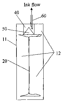
Reference is .row made . ta. Figure. 3 wherein tk~exe i.s deceribed . the ~xst
embodiment of this invention.
Ink cartridge 10 has a housing component 11 closeable with a complementary
housing component to define a single chamber 12 containing ink supply means
(in the
form of plastic ink bottle 20) and ink recovery means built-in in the same
chamber 12
of cartridge 10.
The ink bottle 20 which contains ink has a plastic needle or tube (ie; dip
tube)
30 that is assembled onto the offset bottle neck area. The plastic tube 30
allows ink to
be dispensed out of the ink bottle and thus the cartridge effectively. A one-
way valve
50 is associated with (eg; inserted onto) the bottle neck as well. A rubber
seal plug 40
is plug on to the bottle neck 21 to seal up the bottle, preventing ink leakage
and forming
the supply port 14 of the ink cartridge.
The pre-assembled ink bottle assembly is then assembled onto one half of the
ink cartridge housing 11 as shown. At the waste ink return port 15, another
rubber seal
plug 41 is plugged onto the ink cartridge housing 11.
The other half or complementary housing component of the ink cartridge
housing is then closed and sealed using for example, ultrasonic welding.
CA 02498516 2005-03-10
WO 2004/024453 PCT/SG2003/000142
In use the ink cartridge is associated by insertion into a device (whether or
the
ink jet printer itself or otherwise) so that two cannulas will penetrate
through the rubber
seal plugs 40 and 41 of both the supply port 14 and waste ink return port 1 S
respectively. Upon full penetration, the rubber seal plug 40 and 41 is capable
of self
sealing on the penetrating cannula thus closing fluid communication between
the
cartridge 10 and the device (eg; printer cartridge that requires ink filling
or the inkjet
printer itself) that is using it. The device has normally a suction mechanism
that draw
ink from the supply port 14 and any waste ink resulted from the device is
returned into
the waste ink recovery chamber 12 through the waste ink return ink port 15.
The built in one-way valve 50 is able to ensure better print functionality and
printout quality by restricting waste ink from contaminating the ink in the
ink supply
bottle of the ink cartridge.
The plastic ink bottle 20 is a thin wall bottle made by a blow moulding
process.
It is of a plastic material such as low density polyethylene or other similar
flexible
. material. The bottle wall, being flexible witb. a. careful ~;hoice of mate~-
,ia.l, a~n~ wall ..
thickness, is capable of collapsing when ink is drawn out from the ink bottle
20. When
the ink amount reduces in the ink bottle 20, as a result of being dispensed
out by a
suction mechanism from the device that is using it, the internal pressure will
drop, thus
causing the bottle wall to collapse.
Now, reference is made to Figure 4a and Figure 4b. When the ink bottle 20 is
full of ink, it occupies almost the entire volume of the ink cartridge 10,
leaving a small
amount of empty space to serve as waste ink recovery chamber 12. When ink is
dispensed out through the cannula 60 that penetrates through the rubber seal
plug 40,
ink bottle 20 collapses. In the normal working scenario, where all the ink is
being
depleted and the majority of the ink is being used by the device, the ink
bottle 20 will
fully collapse as shown in Figure 4b. Nevertheless some amount of ink will
return to
the waste ink recovery chamber 12 which is now increased in size due to the
collapse
of ink bottle 20. In the unlikely event of the worst case scenario where all
ink supplied
is returned as waste ink, the waste ink recovery chamber is also sufficient to
contain all
the waste ink within the now fully increased in space waste ink recovery
chamber 12.
Reference is now back to Figure 3.
CA 02498516 2005-03-10
WO 2004/024453 PCT/SG2003/000142
_$_
As opposed to normal blow bottle where the bottle neck is normally at the
center
of the bottle body, ink bottle 20 preferably has a bottle neck 21 offset to
one side of the
bottle body. The body of the ink bottle preferably also has a chamfer or
truncation 22
at the bottom corner on the same side as the bottle neck 21.
The ink cartridge housing 11 preferably has a corresponding chamfered or
truncated comer 13.
The chamfers allows the ink cartridge 10 and thus the ink bottle 20 to be
seated
at an angle, at around 45°. The plastic needle 30 is also specifically
designed to have
a chamfered end 31 facing towards the chamfer 22 area of the ink bottle 20.
The
purpose of this arrangement is to reduce amount of unused ink as illustrated
in Figure
a to Figure 5 d.
Before examining the amount of ink that will remain in the bottle (i.e. ink
that
is unable to be fully dispensed out), it is required to note that there needs
to be
sufficient clearance H between the end of the plastic needle 30 and the wall,
=p~rifcaal,r the ,hamfPr ~.r~a. ??. of the 3n1~ bottle 2~=, fir grope.- ani._
f!o~. ~. '!'~~ 1;~,~
clearance H is undesirable as it will slow down the ink flow rate.
Figure Sa and Figure Sb show that if the plastic needle is either located at
the
center or one side of the bottle, but the bottle is made without a chamfer,
the amount
of unused ink is Ll x H x T. In Figure Sc, if the chamber if added to allow
the cartridge
to be seated in an angle, but the plastic needle has a flat end, the amount of
ink left is
approximately (L2)(H+Y) x T. Figure Sd shows that if the chamber is added to
allow
the cartridge to be seated in an angle, and the end of the plastic needle is
also
chamfered to the same angle, the amount of unused ink is approximately L2 x H
x T.
Since L1 is greater than L2 (L1>L2), the least amount of unused ink will
result from
the design as shown in Figure Sd which is preferably employed in the design of
the
preferred embodiment of the present invention.
Thus, the invention described herein is capable of achieving smaller overall
cartridge size and lower product cost.