Language selection

Search

Patent 2498714 Summary

Third-party information liability

Some of the information on this Web page has been provided by external sources. The Government of Canada is not responsible for the accuracy, reliability or currency of the information supplied by external sources. Users wishing to rely upon this information should consult directly with the source of the information. Content provided by external sources is not subject to official languages, privacy and accessibility requirements.

Claims and Abstract availability

Any discrepancies in the text and image of the Claims and Abstract are due to differing posting times. Text of the Claims and Abstract are posted:

  • At the time the application is open to public inspection;
  • At the time of issue of the patent (grant).
(12) Patent Application: (11) CA 2498714
(54) English Title: SCRUBBER
(54) French Title: EPURATEUR
Status: Deemed Abandoned and Beyond the Period of Reinstatement - Pending Response to Notice of Disregarded Communication
Bibliographic Data
(51) International Patent Classification (IPC):
  • A61B 05/097 (2006.01)
  • A62B 23/00 (2006.01)
  • B01D 53/02 (2006.01)
  • B01D 53/04 (2006.01)
  • G01N 33/497 (2006.01)
(72) Inventors :
  • NILSSON, MIKAEL (Sweden)
  • HEMMINGSSON, TRYGGVE (Sweden)
(73) Owners :
  • AEROCRINE AB
(71) Applicants :
  • AEROCRINE AB (Sweden)
(74) Agent: GOWLING WLG (CANADA) LLP
(74) Associate agent:
(45) Issued:
(86) PCT Filing Date: 2003-08-21
(87) Open to Public Inspection: 2004-03-25
Examination requested: 2008-06-03
Availability of licence: N/A
Dedicated to the Public: N/A
(25) Language of filing: English

Patent Cooperation Treaty (PCT): Yes
(86) PCT Filing Number: PCT/SE2003/001299
(87) International Publication Number: SE2003001299
(85) National Entry: 2005-03-11

(30) Application Priority Data:
Application No. Country/Territory Date
0202741-5 (Sweden) 2002-09-16
0202905-6 (Sweden) 2002-10-02

Abstracts

English Abstract


A scrubber for eliminating NO from air flowing through the scrubber,
comprising a housing (1) having at least one inlet hole (2) and an outlet hole
(4) and which is comprising filtering material (6). A second outlet hole (9)
is provided in the housing (1) at a position situated at a distance from the
first outlet hole (4) and any inlet hole (2) so that the air leaving the
second outlet hole (9) will have flown at least through a depth of the
filtering material (6) substantially corresponding to the depth of the
filtering material (6) for the air flowing from the inlet hole (2) to the
first outlet hole (4).


French Abstract

Cette invention se rapporte à un épurateur servant à éliminer le NO de l'air traversant l'épurateur, lequel comprend un logement (1) comportant au moins un orifice d'admission (2) et un orifice d'émission (4) et constitué par un matériau filtrant (6). Un second orifice d'émission (9) est ménagé dans le logement (1) dans une position située à une certaine distance du premier orifice d'émission (4) et du ou des orifices d'admission (2), pour que l'air quittant le second orifice d'admission (9) ait traversé au moins une épaisseur du matériau filtrant (6) correspondant sensiblement à l'épaisseur du matériau filtrant (6) traversé par l'air s'écoulant de l'orifice d'admission (2) jusqu'au premier orifice d'émission (4).

Claims

Note: Claims are shown in the official language in which they were submitted.

7
Claims
1. A scrubber for eliminating a component from air
flowing through the scrubber, comprising a housing
(1) having at least one inlet hole (2) and an outlet
hole (4) and which is comprising filtering material
(6), characterised in that a second outlet hole (9)
is provided in the housing (1) at a position situated
at a distance from the first outlet hole (4) and any
inlet hole (2) so that the air leaving the second
outlet hole (9) will have passed at least through a
depth of the filtering material (6) substantially
corresponding to the depth of the filtering material
(6) for the air flowing from the inlet hole (2) to
the first outlet hole (4).
2. A scrubber according to claim 1, wherein the second
outlet hole (9) is intended for a smaller throughput
of air than the first outlet hole (4).
3. A scrubber according to claim 1 or 2, wherein several
inlet holes (2) are provided in the housing (1) in an
end side (3) opposite an end side (5) comprising the
first outlet hole (4).
4. A scrubber according to claim 1, 2 or 3, wherein the
second outlet hole (9) is provided at the wall (8) of
the housing (1) between the two end sides (3, 5).
5. A scrubber according to any one of the previous
claims, wherein no inlet holes are present in the end
side (5) comprising the first outlet hole (4) in the
vicinity of the second outlet hole (9) so that the

8
air will flow at least through a depth of the
filtering material substantially corresponding to the
depth of the filtering material (6) for the air
flowing through the first outlet hole (4).
6. A scrubber according to any one of the previous
claims, wherein a non-return valve (11) is provided
in the first outlet hole (4).
7. A scrubber according to any one of the previous
claims, wherein the scrubber is provided for
filtering NO.
8. A scrubber according to claim 7, wherein the filter
material (6) is potassium permanganate KMnO4 or
potassium permanganate in combination with a suitable
grade of carbon.
9. A scrubber according to claim 7 or 8, wherein the
scrubber eliminates NO to a level less than 5 ppb.
10.A scrubber according to any one of the previous
claims, wherein a particle filter (7) is provided
inside the housing (1) at least at the inlet holes
(2) and at the first and second outlet holes (4, 9)
in order to stop the filter material (6) to escape
from the scrubber.
11.A scrubber according to any one of the previous
claims, wherein the flow rate through the first
outlet hole (4) is about 1-10 1/s and the flow rate
through the second outlet hole (9) is about 0,5-50
ml/s.

9
12.A scrubber according to any one of the previous
claims, wherein the size of the particles of the
filtering material is in the range of 1/8-1/128 of an
inch and preferably 1/32-1/64 of an inch.

Description

Note: Descriptions are shown in the official language in which they were submitted.


CA 02498714 2005-03-11
WO 2004/023998 PCT/SE2003/001299
1
Scrubber
The present invention relates to a scrubber for
eliminating a component from air flowing through the
scrubber.
Technical background
Known scrubbers comprise a housing having at least one
inlet hole and an outlet hole and comprising filtering
material. A scrubber may for example be used in any
equipment where for example NO-free air is needed, e.g.
for calibration, as in an equipment for measuring the
level of nitric oxide in air, especially exhalation air,
or any other gas mixture. In such a case a test person
inhales air through the scrubber so that NO will be
filtered from the air. The air flow may for example be
about 1-10 litre/second.
Preferably a return valve is positioned between the
inlet/outlet of the equipment, through which inlet/outlet
the test person inhales/exhales, and the outlet of the
scrubber so that the exhaled air does not pass the
scrubber but reaches any sensing portion of the equipment.
When taking a zero reference for the sensing portion of
the equipment or making a function control, a small flow
of component-free air, for example NO-free air, is used
and taken between the outlet of the scrubber and the
return valve. One problem with this is that the
possibility exists that the zero reference will be mixed
with a leakage back flow through the return valve. This
would compromise the accuracy of. the zero measurement.

CA 02498714 2005-03-11
WO 2004/023998 PCT/SE2003/001299
2
This is of course true for any filtering of a component
from air. Therefore, it is an object of the present
invention to provide a scrubber, which safely makes sure
that the zero reference flow actually comes from the
scrubber and is identical to the component-free air
inhaled by the test person.
Summary of the invention
This object is met by a scrubber according to claim 1.
An advantage with this solution is, in the case of a
leakage or breakage of a return valve, the depth of the
filtering material will still be large enough for
filtering the air, making the system safe. This also gives
the advantage that the return valve may be an ordinary
mechanical one suitable for large flow rates, which is
less expensive, instead of an electrically controlled
valve needed for handling low flow rates.
Another problem with known scrubbers is that the outlet is
designed for large flow rates, which means that there is a
large "dead space" in the outlet with air that has been
stagnant in this space and the zero reference or function
control flow will have to go on for a long time before you
may be sure that the air has flown through the scrubber.
According to an embodiment of the present invention this
second outlet is smaller than the first outlet, whereby
the "dead space" in the second outlet is minimal forming a
very effective system where less air needs to flow through
the scrubber and the system in order to make sure that a
zero reference has been safely registered.

CA 02498714 2005-03-11
WO 2004/023998 PCT/SE2003/001299
3
Preferably the scrubber is provided for filtering NO from
air.
A problem with known NO-scrubbers is that they comprise
carbon filters for the elimination of NO. However, these
scrubbers are not suitable for long-term use. They lose
their capability of eliminating NO quickly when exposed to
humidity even at commonly existent ambient humidity
levels. Another drawback is that they need to be
voluminous to be able to eliminate NO at high flows and
concentrations commonly encountered in urban environments.
Therefore it is also an object of the present invention to
provide a small scrubber, which is suitable for long-term
use. The solution to this is a scrubber comprising
potassium permanganate KMn09 or potassium permanganate in
combination with a suitable grade of carbon. An advantage
with this material is that it binds NO and forms manganese
dioxide. This retains its filtering capability in
moisturous environments, actually better than in dry
environments.
Short description of the drawings
The present invention will be described showing an
embodiment of a scrubber according to the present
invention together with drawings, in which:
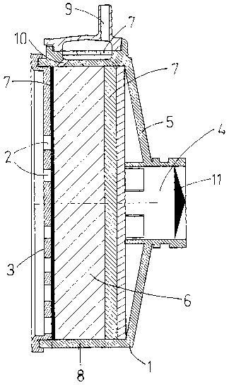
Fig. 1 illustrates a cross section view of an embodiment
of a scrubber according to the present invention.
Fig. 2 illustrates the scrubber of Fig. 1 in a view
showing an end side having inlet holes.

CA 02498714 2005-03-11
WO 2004/023998 PCT/SE2003/001299
4
Fig. 3 illustrates the scrubber of Fig. 1 in a
perspective view.
Detailed description of a preferred embodiment
The scrubber of the present invention comprises a housing
1 having at least one inlet hole 2, in the shown
embodiment several small inlet holes 2 spread over an end
side 3, and a first outlet hole 4 in the end side 5
opposite the inlet end side 3. Within the housing 1 is a
filtering material 6 present.
Between the housing 1 and the filtering material 6 at the
inlet holes 2 and the first outlet hole 4 is a particle
filter 7 present to stop particles of the filtering
material 6 from leaving the scrubber through the holes 2,
4.
The scrubber of the shown embodiment has a cylindrical
wall 8 between the two end sides 3, 5 but of course other
shapes are conceivable. At the wall 8 a second outlet hole
9 is present. Also this hole 9 is protected on the inside
with a particle filter 7 to stop particles of the
filtering material 6 from leaving the scrubber through the
second hole 9. In the shown embodiment the air flowing
through the filtering material 6 from the inlet holes 2 to
the second outlet 9 passes via a channel 10.
The first outlet hole 4 is designed for a throughput of
about 1-10 litres/second of air and the second outlet hole
9 is designed for a throughput of about 0,5-50
millilitres/second, preferably.

CA 02498714 2005-03-11
WO 2004/023998 PCT/SE2003/001299
In order to make sure that the air leaving the second
outlet hole 9 has passed a sufficient depth of the
filtering material 6, there are not any inlet holes 2 in
the inlet end side 3 in the vicinity of the second outlet
5 hole 9. In such way the air must travel a depth in the
filtering material 6, for example at least corresponding
substantially to the depth for the air to travel between
the inlet holes 2 and the first outlet hole 4, making sure
that the component, for example N0, will be filtered from
the air.
In order to make the air flow from the inlet holes 2 to
the second outlet hole 9 and not from the first outlet
hole 4 to the second outlet hole 9 a return valve 11 may
be arranged in the first outlet hole 4 or outside in the
extension of the outlet hole 4.
As a safety measure, in case of leakage in the return
valve 11, the second outlet 9 should be provided at a
distance from the first outlet valve 4 also. Thus the air
must travel a depth in the filtering material 6 at least
corresponding substantially to depth for the air to travel
between the inlet holes 2 and the first outlet hole 4,
making sure that the component, for example N0, will be
filtered from the air.
The filtering material 6 is preferably potassium
permanganate KMn04 or potassium permanganate in combination
with a suitable grade of carbon in granular form if the
component to be removed is N0. The granules may have the
size 1/8-1/128 of an inch and preferably 1/32-1/64 of an
inch. Preferably the air leaving the scrubber from any of
the outlet holes 4, 9 has a content of NO less than 5 ppb,
in general in urban environments.

CA 02498714 2005-03-11
WO 2004/023998 PCT/SE2003/001299
6
The present invention is not limited to the shown and
described embodiments but can be varied and amended within
the scope of the attached claims.

Representative Drawing
A single figure which represents the drawing illustrating the invention.
Administrative Status

2024-08-01:As part of the Next Generation Patents (NGP) transition, the Canadian Patents Database (CPD) now contains a more detailed Event History, which replicates the Event Log of our new back-office solution.

Please note that "Inactive:" events refers to events no longer in use in our new back-office solution.

For a clearer understanding of the status of the application/patent presented on this page, the site Disclaimer , as well as the definitions for Patent , Event History , Maintenance Fee  and Payment History  should be consulted.

Event History

Description Date
Application Not Reinstated by Deadline 2011-08-22
Time Limit for Reversal Expired 2011-08-22
Deemed Abandoned - Failure to Respond to Maintenance Fee Notice 2010-08-23
Amendment Received - Voluntary Amendment 2008-09-22
Letter Sent 2008-08-18
Request for Examination Received 2008-06-03
All Requirements for Examination Determined Compliant 2008-06-03
Request for Examination Requirements Determined Compliant 2008-06-03
Inactive: IPC from MCD 2006-03-12
Letter Sent 2005-06-06
Inactive: Cover page published 2005-05-30
Inactive: Notice - National entry - No RFE 2005-05-24
Inactive: Single transfer 2005-05-02
Application Received - PCT 2005-04-04
National Entry Requirements Determined Compliant 2005-03-11
Application Published (Open to Public Inspection) 2004-03-25

Abandonment History

Abandonment Date Reason Reinstatement Date
2010-08-23

Maintenance Fee

The last payment was received on 2009-08-07

Note : If the full payment has not been received on or before the date indicated, a further fee may be required which may be one of the following

  • the reinstatement fee;
  • the late payment fee; or
  • additional fee to reverse deemed expiry.

Patent fees are adjusted on the 1st of January every year. The amounts above are the current amounts if received by December 31 of the current year.
Please refer to the CIPO Patent Fees web page to see all current fee amounts.

Fee History

Fee Type Anniversary Year Due Date Paid Date
Basic national fee - standard 2005-03-11
Registration of a document 2005-05-02
MF (application, 2nd anniv.) - standard 02 2005-08-22 2005-07-28
MF (application, 3rd anniv.) - standard 03 2006-08-21 2006-07-24
MF (application, 4th anniv.) - standard 04 2007-08-21 2007-08-07
Request for examination - standard 2008-06-03
MF (application, 5th anniv.) - standard 05 2008-08-21 2008-08-01
MF (application, 6th anniv.) - standard 06 2009-08-21 2009-08-07
Owners on Record

Note: Records showing the ownership history in alphabetical order.

Current Owners on Record
AEROCRINE AB
Past Owners on Record
MIKAEL NILSSON
TRYGGVE HEMMINGSSON
Past Owners that do not appear in the "Owners on Record" listing will appear in other documentation within the application.
Documents

To view selected files, please enter reCAPTCHA code :


To view images, click a link in the Document Description column. To download the documents, select one or more checkboxes in the first column and then click the "Download Selected in PDF format (Zip Archive)" or the "Download Selected as Single PDF" button.

List of published and non-published patent-specific documents on the CPD .

If you have any difficulty accessing content, you can call the Client Service Centre at 1-866-997-1936 or send them an e-mail at CIPO Client Service Centre.


Document
Description 
Date
(yyyy-mm-dd) 
Number of pages   Size of Image (KB) 
Abstract 2005-03-10 2 73
Description 2005-03-10 6 181
Representative drawing 2005-03-10 1 27
Drawings 2005-03-10 2 52
Claims 2005-03-10 3 68
Reminder of maintenance fee due 2005-05-23 1 110
Notice of National Entry 2005-05-23 1 192
Courtesy - Certificate of registration (related document(s)) 2005-06-05 1 104
Reminder - Request for Examination 2008-04-21 1 126
Acknowledgement of Request for Examination 2008-08-17 1 176
Courtesy - Abandonment Letter (Maintenance Fee) 2010-10-17 1 175
PCT 2005-03-10 3 88
Correspondence 2006-10-22 1 28
Fees 2007-08-06 1 39
Fees 2008-07-31 1 40
Fees 2009-08-06 1 42