Note: Descriptions are shown in the official language in which they were submitted.
CA 02499104 2005-03-O1
Docket 2000.129A
DIRECT METHANOL FUEL CELL
Related Application
This application is a continuation-in-part of co-pending U.S.
Patent application serial No. 10/798,032 filed March 11, 2004.
Field of the Invention
The application is directed to a direct methanol fuel cell
(DMFC) .
Background of the Invention
The direct methanol fuel cell (DMFC) catalytically oxidizes
methanol to generate electricity. The DMFC differs from PEM
(proton exchange membrane) or solid polymer fuel cells, which use
hydrogen gas for generating electricity. One major advantage of
the DMFC over the PEM fuel cell is its ability to use methanol, a
relatively inexpensive and easily handled material when compared to
hydrogen gas. One major disadvantage of the DMFC, when compared to
the PEM fuel cell, is methanol crossover. Methanol crossover
occurs when methanol from the anode crosses to the cathode. This
causes the loss of efficiency of the cell. Nevertheless, the DMFC
appears to be a viable portable power source for devices such as
cellular or mobile telephones, and handheld or laptop computers.
- 1 -
CA 02499104 2005-03-O1
"Types of Fuel Cells," Fuel Cells 2000, www.fuelcells.org; Thomas,
et al, "Fuel Cells-Green Power," Los Alamos National Laboratory,
LA-VR-99-3231.
The DMFC is an electrochemical device. The anodic catalyzed
reaction is:
CH30H + H20 > C02 + 6H+ + 6e-
The cathodic catalyzed reaction is:
3 /2 Oz + 6H+ + 6e- > 3H20
The overall cell reaction is:
CH30H + 3 / 2 Oz > C02 + 2 H20
These cells operate at efficiencies of about 40~ at temperatures of
50-100°C, the efficiencies will increase at higher operating
temperatures. Fuel Cells 2000, Ibid; Thomas, Ibid.
As with any chemical reaction, reactants, products, and
unwanted products (by-products) become mixed as the reaction
proceeds, and separation of these materials is an engineering
challenge. So, at the anode, methanol, water, and carbon dioxide
will be mixed together. One must be careful that excess methanol
not accumulate at the anode because it will crossover the proton
conducting membrane (PCM) and decrease the cell's efficiency.
Water is good for the PCM, which needs water to maintain its proton
conductivity, but if water accumulates, it can prevent methanol
- 2 -
CA 02499104 2005-03-O1
from reaching the catalyst, or it can be recycled back into fuel
mixture where it can dilute the fuel. Both can decrease the
efficiency of the cell. Carbon dioxide (or COXs) must be removed
to allow room for the fuel at the anode. Otherwise, cell
efficiency can suffer.
Likewise, at the cathode, oxygen typically from air, must
reach the cathode and water must be removed. If oxygen cannot
reach the cathode, efficiency drops because the cathode half cell
reaction is impeded. If water, which can be used to moisten the
PCM, is allowed to accumulate, it will prevent oxygen from reaching
the cathode.
One challenge related to the foregoing is managing the
reactant/product issues without greatly increasing the size or
weight of the DMFC. DMFC is targeted, in part, at a portable power
source for cellular or mobile telephones and handheld or laptop
computers.
In WO 02/45196 A2, a DMFC is disclosed. Referring to Figure 3,
the DMFC 40 has proton conducting membrane (PCM) 80 with C02
conducting elements 52. On the anode side 41, there is a
conducting plate 23 that has a flow field 25, a gas diffusion layer
44, and an anodic catalyst 42. On the cathode side 31, there is a
- 3 -
CA 02499104 2005-03-O1
conducting plate 33 with a flow field 35, a gas diffusion layer 48,
and a cathode catalyst 46. The catalyst, anode or cathode, is
applied to either a surface of the PCM 80 or to the gas diffusion
layers 44, 48. The respective flow fields are in communication
with their respective gas diffusion layers and the combined action
of these flow fields and diffusion layers is intended to ensure the
even distribution of reactants to the catalyst and the efficient
removal of unwanted products, by-products, and unreacted reactants
for the reaction. The gas diffusion layers are made of carbon
fiber paper and/or carbon fiber cloth and may be "wet-proofed" with
PTFE polymer. Note that the gas diffusion layer, catalyst, and PCM
are in close contact to promote electrons or protons conductivity.
On the anode side, fuel (methanol, methanol/water in either
liquid or vapor form) is introduced at one end of the flow field
25, and by products (water, COz, and un-reacted fuel) are removed
at other end of the flow field 25. COz produced at the anode is
intended to cross the PCM 80 via COZ conductors 52. Water produced
at the anode is not meant to remain in the gas diffusion layer 42
as is apparent from the use of the PTFE. On the cathode side, air
(the source of OZ) is introduced at one end of flow field 35, and
water, unreacted air, and C02 are removed at the other end of flow
field 35. Water produced at the cathode is not intended to remain
- 4 -
CA 02499104 2005-03-O1
in the gas diffusion layer 48 as is apparent from the use of the
PTFE.
In U.S. Patent Application Publication 2002/0192537 A1,
another DMFC is disclosed. This DMFC is similar to the foregoing
DMFC, except the carbon paper or carbon cloth gas diffusion layers
are replaced with a porous metal layer. See paragraphs [0022-
0024] .
Accordingly, there is a need to improve reactant, product, and
by-product management at both the anode and cathode of DMFC while
not significantly increasing the size or weight of the DMFC.
Summary of the Invention
A direct methanol fuel cell has a proton conducting membrane
(PCM), a catalyst in contact with the PCM, a gas diffusion layer in
contact with the catalyst, and a conducting plate in contact with
the gas diffusion membrane. The gas diffusion layer comprises a
non-metallic microporous membrane. The non-metallic microporous
membrane may be a microporous membrane, a laminate of a microporous
membrane, and a skinned microporous membrane.
- 5 -
CA 02499104 2005-03-O1
Description of the Drawings
For the purpose of illustrating the invention, there is shown
in the drawings a form that is presently preferred; it being
understood, however, that this invention is not limited to the
precise arrangements and instrumentalities shown.
Figure 1 is a schematic illustration of a direct methanol fuel
cell (DMFC) made according to the present invention.
Figure 2 is a photomicrograph (SEM X5000) of an asymmetric
membrane showing the side with the large pores.
Figure 3 is a photomicrograph (SEM X5000) of the asymmetric
membrane of Figure 2 showing the side with the small pores.
Figure 4 is a photomicrograph (SEM X1000) of the asymmetric
membrane of Figure 2 showing a cross-sectional view of the
membrane.
Figure 5 is a photomicrograph (SEM X15000) of a skinned
membrane showing the side with the large pores.
Figure 6 is a photomicrograph (SEM X15000) of the skinned
membrane of Figure 5 showing the side with the no pores.
- 6 -
CA 02499104 2005-03-O1
Figure 7 is a photomicrograph (SEM X15000) of the skinned
membrane of Figure 5 showing a cross-section of the side with no
pores.
Figure 8 is a schematic illustration of a plurality of DMFC's
connected in series.
Figure 9 is a schematic illustration of a plurality of DMFC's
connected in parallel.
Description of the Invention
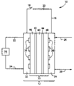
Referring to the drawings, wherein like elements have like
numerals, there is shown in Figure 1 a direct methanol fuel cell
system 10.
DMFC system 10 includes a DMFC 12, a fuel source 14, and an
electrical circuit 16. DMFC may include one or more DMFC. Fuel
source 14 is a storage vessel that contains the fuel, methanol, or
a mixture of methanol and water. Electrical circuit 16 includes a
switch 18 and a load 20. Load 20 may be any device that requires
electricity, such as a cellular or mobile telephone, or a handheld
or laptop computer, or the like. Fuel is supplied to DMFC 12 via
line 22 from source 14 and is returned to source 14 via line 24
CA 02499104 2005-03-O1
from DMFC 12. Air is supplied to DMFC 12 via line 26 and vented
from DMFC 12 via line 28.
DMFC 12 includes a membrane electrode assembly (MEA) 30
preferably sandwiched between a pair of collection plates 32, 34.
Collection plates are electrically conductive and are coupled to
electrical circuit 16. Collection plate 32 includes a fuel
distribution channel 36. One end of channel 36 is in fluid
communication with line 22 and the other end of channel 36 is in
fluid communication with line 24. Collection plate 34 includes an
oxidant distribution channel 38. One end of channel 38 is in fluid
communication with line 26 and the other end is in fluid
communication with line 28. The geometry of channels 36 and 38 is
such that fuel or oxidant is evenly distributed to the catalysts of
the DMFC 12.
MEA 30 includes a proton conducting membrane (PCM) 40 with an
anode catalyst 42 on one side thereof and a cathode catalyst 44 on
the other side thereof and all sandwiched between gas diffusion
layers 46 and 48. PCM 40 is conventional, for example NAFION° from
DuPont, Wilmington, DE or the hybrid set forth in WO 02/45196A2,
incorporated herein by reference. Anode catalyst 42 may be adhered
to a face of PCM 40 or adhered to the fiber surfaces of a carbon
fiber mat or cloth. Likewise, cathode catalyst 44 may be adhered
_ g _
CA 02499104 2005-03-O1
to the other face of PCM 40 or adhered to fiber surfaces of a
carbon fiber mat or cloth. The anode and cathode catalyst are
conventional and the methods of adhering same are also
conventional.
The gas diffusion layers 46 and 48 may comprise a non-metallic
microporous membrane. Non-metallic microporous membrane, as used
herein, includes a microporous membrane, a laminate of a
microporous membrane (e.g., one or more membranes, or membranes and
coatings), and a skinned microporous membrane. Optionally, the
non-metallic microporous membrane may include a fiber substrate,
e.g., a carbon fiber substrate. Such membranes may be further
characterized as flat sheet membranes having a thickness from 1 to
300 microns.
The non-metallic microporous membrane may take on several
different forms, the ultimate form being dependent upon the desired
function of the membrane. Functions of the membrane will be
dependent upon whether it is located on the anode side or the
cathode side. Functions for membranes at the anode side may
include, alone or in combination: allowing the fuel to pass to the
catalyst; preventing accumulation of water at the catalyst; removal
of water from the catalyst, but not to the fuel source; preventing
accumulation of MeOH at the catalyst thereby reducing the chance
_ g _
CA 02499104 2005-03-O1
for methanol crossover, allowing MeOH to return to the fuel source,
preventing accumulation of C02 at the catalyst. Functions for
membranes at the cathode side may include, alone or in combination:
removal of unnecessary water; removal of COz.
Non-metallic membranes suitable to address these functions
include polymeric or ceramic microporous or nonporous membranes,
skinned membranes, symmetric or asymmetric membranes, single or
multi-layered membranes, and combinations thereof. Such membranes
are known, see for example, Kesting, R., Synthetic Polymeric
Membranes, 2nd Edition, John Wiley & Sons, New York, NY (1985),
incorporated herein by reference. Such membranes can be made of
various polymers, for example, polyolefins (e. g., polyethylene,
polypropylene, poly-3-methylbutene-1, poly-4-methylpentene-1),
vinyl polymers (e. g., polystyrene, poly(methyl methacrylate),
fluorine-containing polymers (e. g., polyvinylidene,
polyvinyltrimethylsilane, fluorovinylethylene/tetrafluoroethylene
copolymer), polyamides (e. g., nylon 6, nylon 66, nylon 12),
polyesters (e. g., polyester terphthalate, polybutylene
terephthalate, polyethylene-2,6-naphthalate), polycarbonates (e. g.,
poly-4,4'-dihydroxydiphenyl-2,2-propane carbonate), polyethers
(e. g., polyoxymethylene, polymethylene sulfide), polyphenylene
chalcogenides (e. g., polythioether, polyphenylene oxide,
polyphenylene sulfide), polyether ether ketones (PEEK), polysulfone
- 10 -
CA 02499104 2005-03-O1
(PS), polyethersulfone (PES), polyimides, polyetherimides (PEI),
cellulose acetate (CA), polydimethylsiloxane, blends of the
foregoing, compositions including other materials wherein the
foregoing polymer comprises a majority of the composition, and
copolymers thereof.
Asymmetric membranes include membranes with diameters that
vary from one surface to another (e. g., pores with decreasing
diameters from one surface of the membranes to the other; pores
with decreasing diameters from one surface to a point between the
membrane surfaces and increasing diameters to the opposite surface;
pores with increasing diameters from one surface to a point between
the membrane surfaces and decreasing diameters to the opposite
surface) .
Skinned microporous membranes include microporous membranes,
symmetric or asymmetric, that have at least one "dense" gas
separation layer. Typically, this dense layer is located at one or
both of the membrane's surfaces, but may be located within the
membrane's interior (i.e., between the surfaces). Additionally,
the dense layer may be hydrophobic or hydrophilic. The dense layer
may be characterized as non-porous, but may include nanopores. The
dense layer may have a gas selectivity, i.e., the ability to
diffuse one material preferentially over another. Exemplary dense
- 11 -
CA 02499104 2005-03-O1
layers may have 02/Nz gas selectivities of 1.2 or greater or 2.0 or
greater. Exemplary dense layers may have COz/N2 selectivities of
6.0 or greater or 8.0 or greater.
Additionally, the membranes may have functional
coatings/additives, for example, hydrophobic or hydrophilic
materials. Such materials are conventional. The membranes may
also include perm-selective gels or polymers that preferably pass
one or more of the reactants, products, or by-products. Such perm-
selective gels or polymers are conventional. Such a perm-selective
material could, for example, coat one or more sides of the membrane
or be sandwiched between membranes.
As an example of the foregoing, one may use an asymmetric
membrane (pores with decreasing diameters from one surface of the
membranes to the other) that is coated with a hydrophobic material
on the surface with the narrow pores. This membrane, which could
be used at either the anode or cathode, would be placed in the MEA
with the coated face toward the PCM. Thereby, water, a reactant at
the anode and a product at the cathode, and retained around the
PCM, is available to moisten the PCM so that its proton
conductivity is maintained.
- 12 -
CA 02499104 2005-03-O1
By way of further example of asymmetric membranes reference is
made to U.S. Patent No. 4,664,681 which discusses asymmetric
membranes, incorporated herein by reference. Such membranes can be
made of various polymers, note the list of polymers set forth
above. These membranes are further characterized as having an
apparent oxygen permeability coefficient at room temperature (25°C)
that is at least 3 times greater than the apparent oxygen
permeability coefficient (Q25°C) for the corresponding homogeneous
(symmetrical) membrane, and having an oxygen-nitrogen separation
coefficient (Q25°C) of at least 1.2.
By way of still further example of asymmetric membranes,
reference is made to Figures 2, 3, and 4, photomicrographs of a PMP
(polymethylpentene) asymmetric membrane. Figures 2 - 4 illustrate
an asymmetric membrane having pores that have decreasing diameters
from one surface to the other. In Figure 2, the surface having
large pores is illustrated. In Figure 3, the surface with small
pores is illustrated. Figure 4 is a cross-sectional view of the
membrane with the large pore side at the bottom and the small pore
side at the top.
By way of yet another example of non-metallic microporous
membranes, reference is made to Figures 5, 6, and 7,
photomicrographs of a PMP (polymethylpentene) skinned membrane.
- 13 -
CA 02499104 2005-03-O1
Figures 5 - 7 illustrate skinned membrane having pores that have
decreasing diameters from one surface to no pores at the other. In
Figure 5, the surface having large pores is illustrated. In Figure
6, the surface with no pores is illustrated. Figure 7 is a cross-
sectional view of part of the membrane with the dense layer at the
right.
Figures 8 and 9 illustrate further embodiments of the
invention. In these embodiments, a plurality of DMFC's are joined
together to form a stack 50. In Figure 8, the DMFC's 12 are joined
in series. In Figure 9, the DMFC's 12 are joined in parallel.
The present invention may be embodied in other forms without
departing from the spirit and the essential attributes thereof,
and, accordingly, reference should be made to the appended claims,
rather than to the foregoing specification, as indicated the scope
of the invention.
- 14 -