Note: Descriptions are shown in the official language in which they were submitted.
CA 02499122 2011-07-21
ACTIVATOR FOR A DISPENSER SWITCH
Background of the Invention
1. Field of the invention
The present invention relates to a product dispenser having a combination
push button and bottle lever for activating a water valve in the product
dispenser to
dispense the product.
2. Inscription of the Prior Art
Product dispensers including an aspirator to dilute a concentrate with a
diluent to form a use solution, which is dispensed from the dispenser, are
well
known. A typical prior art dilution dispenser includes a product concentrate
reservoir, a diluent source, and an aspirator. A container, such as a bottle
or a
bucket, receives the use solution dispensed from the dispenser. The diluent
(e.g.
water) is passed through the aspirator, and a venturi in the aspirator draws
the
concentrate into contact with the diluent and mixes them together to create
the use
solution. Many configurations of these components are possible.
A hose or conduit may be operatively connected to the dispensing end of the
aspirator to carry the use solution to the desired container. When activating
the
dispenser, it is oaten necessary to place the hose or conduit in the container
and then
manually activate a push button on the dispenser. Alternatively, some
dispensers
include a push button that is activated by pressing a bottle against a lever
proximate
the dispensing end of the aspirator. However, these types of dispenser do not
readily
accommodate both bottles and buckets.
Sru mwoLqf tF e, Invention
In a preferred embodiment actuator for use with a dispenser for dispensing a
product concentrate into a container, the dispenser includes an aspirator, a
valve, and
an activation switch. The aspirator has a liquid diluent inlet, a product
concentrate
inlet, and a use solution outlet. The valve is operatively connected to the
aspirator,
and the valve controls flow of liquid diluent from a liquid diluent source to
the
liquid diluent inlet. The activation switch has an end portion and is
operatively
connected to the valve. The activation switch controls the valve. The actuator
I
CA 02499122 2005-03-16
WO 2004/033359 PCT/US2003/029592
includes a first end, an extension portion, an angled portion, and a second
end. The
angled portion interconnects the first end and the extension portion, and the
second
end is operatively connected to and extends from the extension portion. The
second
end is configured and arranged to be contacted by the container. A slot
extends
from the first end to the angled portion, and the end portion of the
activation switch
extends through the slot, wherein the slot does not interfere with the end
portion.
The actuator has a first position wherein the activation switch is in a first
state and a
second position wherein the angled portion contacts the activation switch and
moves
the activation switch to a second state. The slot does not interfere with the
end
portion of the activation switch
In a preferred embodiment dispenser for dispensing a product concentrate, an
aspirator has a liquid diluent inlet, a product concentrate inlet, and a use
solution
outlet. A valve is operatively connected to the aspirator, and the valve
controls flow
of liquid diluent from a liquid diluent source to the liquid diluent inlet. An
activation switch is operatively connected to the valve, and the activation
switch
controls the valve. An actuator has a first end, a second end, an intermediate
portion, and a slot. The first end is proximate the activation switch, the
intermediate
portion interconnects the first end and the second end, and the slot extends
from the
first end to the intermediate portion and allows access to the activation
switch
without interfering with the activation switch. The activation switch is
activated by
one of two ways. The first way is by moving the actuator in a first direction
with a
container thereby moving the activation switch in a second direction, and the
second
way is by moving the activation switch in the second direction.
In a preferred embodiment apparatus for diluting a liquid concentrate with a
liquid diluent to form a dilute use solution for dispensing the dilute use
solution into
a container, an aspirator has a liquid diluent inlet, a product concentrate
inlet, and a
use solution outlet. A valve is operatively connected to the aspirator, and
the valve
controls flow of liquid diluent from a liquid diluent source to the liquid
diluent inlet.
An activation switch is operatively connected to the valve, and the activation
switch
controls the valve. An actuator has a first end and a second end. The first
end has
an aperture through which the activation switch extends and the second end is
proximate the use solution outlet, wherein movement of the actuator in a first
2
CA 02499122 2005-03-16
WO 2004/033359 PCT/US2003/029592
direction presses the activation switch in a second direction to create the
dilute use
solution, and wherein movement of the activation switch in the second
direction
creates the dilute use solution.
In a preferred embodiment dispensing system for supplying a plurality of use
solutions, a dispenser has an aspirator, a valve, and an activation switch.
The
aspirator includes a liquid diluent inlet, a product concentrate inlet, and a
use
solution outlet. The valve is operatively connected to the aspirator, and the
valve
controls flow of liquid diluent from a liquid diluent source to the liquid
diluent inlet.
The activation switch is operatively connected to the valve, and the
activation switch
controls the valve. An actuator has a first end, a second end, an intermediate
portion, and a slot. The first end is proximate the activation switch, the
intermediate
portion interconnects the first end and the second end, and the slot extends
from the
first end to the intermediate portion. The activation switch extends through
the slot
and the slot does not interfere with the activation switch. The activation
switch is
activated one of two following ways. The first way is by moving the actuator
in a
first direction with a container thereby moving the activation switch in a
second
direction, and the second way is by moving the activation switch in the second
direction. A conduit is operatively connected to the use solution outlet, and
a
container is configured and arranged to receive the conduit and to contain one
of the
plurality of use solutions.
In a preferred embodiment method of dispensing a use solution into a
container from a dispenser, the dispenser has an aspirator, a conduit, a
valve, an
activation switch, and an actuator. The aspirator has a liquid diluent inlet,
a product
concentrate inlet, and a use solution outlet. The conduit is in fluid
communication
with the use solution outlet. The valve is operatively connected to the
aspirator to
control flow of liquid diluent from a liquid diluent source into the liquid
diluent
inlet. The activation switch is operatively connected to the valve, and the
activation
switch activates the valve. The actuator is configured and arranged to
activate the
activation switch thereby activating the valve, and the activation switch
extends
through the actuator. The conduit is inserted into the container. The
activation
switch is activated by one of two following ways. The first way is by moving
the
actuator in a first direction with a container thereby moving the activation
switch in
3
CA 02499122 2005-03-16
WO 2004/033359 PCT/US2003/029592
a second direction, and the second way is by moving the activation switch in
the
second direction. The use solution is then dispensed into the container.
In a preferred embodiment method of dispensing a use solution into a
container from a dispenser, the dispenser has an aspirator, a conduit, a
valve, an
activation switch, and a actuator. The aspirator has a liquid diluent inlet, a
product
concentrate inlet, and a use solution outlet. The conduit is in fluid
communication
with the use solution outlet and has a longitudinal axis. The valve is
operatively
connected to the aspirator to control flow of liquid diluent from a liquid
diluent
source into the liquid diluent inlet. The activation switch is operatively
connected to
the valve, and the activation switch activates the valve. The actuator is
configured
and arranged to activate the activation switch thereby activating the valve. A
bottle
is placed under the dispenser, and the conduit is inserted into the bottle.
The bottle
is moved along a line substantially parallel to the longitudinal axis of the
outlet
conduit to activate dispensing of the use solution. The bottle is removed from
under
the dispenser. A bucket is placed proximate the dispenser, and the conduit is
inserted into the bucket. The activation switch is pressed to activate
dispensing of
the use solution.
In a preferred embodiment method of dispensing a use solution into a
container from a dispenser, an activation switch is provided, and the
activation
switch activates a valve, which controls an aspirator. An actuator having a
first end,
a second end, an intermediate portion, and a slot is provided. The first end
is
proximate the activation switch, the intermediate portion interconnects the
first end
and the second end, and the slot extends from the first end to the
intermediate
portion. The slot allows access to the activation switch and does not
interfere with
the activation switch. The activation switch is activated in one of two
following
ways. The first way is by moving the actuator in a first direction with a
container
thereby moving the activation switch in a second direction, and the second way
is by
moving the activation switch in the second direction.
Brief Description of the Drawings
Figure 1 is a partially exploded perspective view of a dispenser constructed
according to the principles of the present invention;
4
CA 02499122 2011-07-21
Figure 2 is a side view'of the dispenser drown in Figure 1 not activated;
Figure 3 is a side view of the dispenser shown in Figure 1 activated to
dispense product;
Figure 4a is a front view of a push button of the dispenser shown in Figure 1
not activated;
Figure 4b is a side view of a push button and a bottle lever of the dispenser
shown in Figure 1 not activated;
Figure Sa is a front view of a push button of the dispenser shown in Figure 1
activated to dispense product; and
Figure 5b is a side view of a push button and a bottle lever of the dispenser
shown in Figure I activated to dispense product.
Detailed Description of a Preferred Fm. `meat
A dispenser constructed according to the principles of the present invention
is designated by the numeral 100 in the drawings.
The dispenser 100 is a dispenser for filling both spray bottles and mop
buckets or other suitable containers well known in the art with a diluted
product,
The present invention is a modification of the dispenser disclosed in U.S.
Patent
5,832,972 by `T`homas et at. The present
invention modifies the slide actuator by adding a slot through which the
activation
switch extends. 3"herefore, the activation switch may be activated in two
different
ways. One way is to simply manually press the push button operatively
connected
to the activation switch. The second way is to use a spray bottle to press the
member or bottle lever in an upward direction thereby sliding the actuator
upward to
press the activation switch. The activation switch activates the water valve
of the
dispenser to fill the container.
A more detailed
description of the present invention follows.
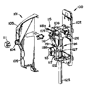
As shown in Figure 1, the dispenser 100 includes a housing 101, which has a
base 102 and a cover 103. The base 102 provides a mounting surface for
mounting
the dispenser 100 to a surface such as a wall and for operatively connecting
other
components of the dispenser 100. The cover 103 is configured and arranged to
5
CA 02499122 2005-03-16
WO 2004/033359 PCT/US2003/029592
engage the base 102 and to cover the other components. The cover 103 includes
an
opening 104 and an opening 105.
The housing 101 houses a valve 107, which is activated by an activation
switch 108. A slide or guide member 109 is operatively connected to the
activation
switch 108 and an extender 110 is operatively connected to the guide member
109.
The guide member 109 includes a flange member 109a. The extender 110 extends
through opening 104 in the cover 103. A knob 111 is operatively connected to
the
extender 110 and provides a push button to activate the activation switch 108
when
pressed. The knob 111 allows for manual activation of the activation switch
108.
Although the preferred embodiment shows the activation switch 108, the guide
member 109, the extender 110, and the knob 111 as separate pieces, it is
recognized
that these components could be one piece or several pieces. The single
component
activation switch has an end portion extending through the opening 104.
The valve 107 controls the diluent input into an aspirator 114. The aspirator
114 includes a venturi driven by water pressure to draw in the product
concentrate as
the diluent flows through the aspirator 114. The aspirator 114 includes a
diluent
inlet 126, a product concentrate inlet 127, and a use solution outlet 128. As
shown
in Figures 1-3, there are two product concentrate inlets 127 on each side, two
of
which are not shown. This allows four different product concentrates to be
utilized
with the dispenser 100. A use solution outlet conduit 125 is operatively
connected
to the use solution outlet 128. The velocity of the diluent through the
diluent inlet
126 and the venturi causes a reduction in pressure, draws the product
concentrate
into the aspirator 114 through the product concentrate inlet 127, generally
causing a
mixing of the product concentrate and diluent. Once the product concentrate
and the
diluent are mixed, a use solution is formed, which exits the aspirator 114
through the
use solution outlet 128 and the use solution outlet conduit 125.
An air gap 112 should also be used to conform with plumbing code
requirements, and the present invention utilizes an aspirator including an air
gap
such as a F1exGapTM aspirator manufactured by Knight, INC. of Lake Forest,
California. The air gap 112 should be used to separate the outlet of the
potable
water supply from any potential contamination to ensure reliable back-flow
protection. An Air Gap Proportioner, 4 gpm, number 10070400, manufactured by
6
CA 02499122 2005-03-16
WO 2004/033359 PCT/US2003/029592
Hydro Systems Company of Cincinnati, Ohio could also be used. Typically a 1
gpm
aspirator is used to fill bottles and a 4 gpm aspirator is used to fill mop
buckets. The
preferred embodiment utilizes a 1 gpm aspirator to readily accommodate both
bottles and buckets along with other suitable containers. However, it is
recognized
that any size aspirator may be used with the dispenser to correspond with the
desired
use of the dispenser. A suitable aspirator may even be swapped with an
existing
aspirator to accommodate different uses of the dispenser, and the dispenser
may be
retrofitted for such different uses.
In the preferred embodiment, water is used as the diluent. A water supply is
connected to the diluent inlet 126 and a concentrated product is connected to
the
product concentrate inlet 127. The preferred embodiment utilizes a liquid
product
concentrate, however, it is understood that solid product concentrates could
also be
utilized with appropriate dilution apparatus and methods well known in the
art.
Generally, the product concentrate could be general purpose cleaning and
sanitizing
compositions and other useful institutional or industrial liquid concentrate
compositions such as window cleaners, hand soap, surface cleaners,
disinfectants,
floor finishes, and air fresheners. However, this list is for illustrative
purposes only
and is not exhaustive.
A product selector 113 extends through the opening 105 in the cover 103,
and the product selector 113 rotates to select which of the four products is
to be
dispensed. The product selector 113 activates the desired product concentrate
inlet
127.
A slide actuator 115 is a thin, elongate member including a first end 115a, an
angled portion 115b, an extension portion 115c, and a second end 115d. An
intermediate portion includes the angled portion 11 5b and the extension
portion
115c. The preferred embodiment slide actuator 115 is made of metal, but any
suitable material known in the art may be used. The first end 115a extends
generally
in an upward direction proximate the top of the dispenser, and the extension
portion
115c also extends generally in an upward direction, parallel to the first end
115a and
proximate the bottom of the dispenser. The angled portion 115b slants from the
first
end 115a toward the extension portion 115c and interconnects these two
portions.
The second end 115d extends generally horizontally from the extension portion
115c
7
CA 02499122 2005-03-16
WO 2004/033359 PCT/US2003/029592
at approximately a 90 angle. It is also possible for the intermediate portion
to be
one portion and interconnect the first end 11 5a and the second end 11 5d at
an angle.
The first end 11 5a and the angled portion 115b include a first slot 116
extending proximate the middle of the first end 11 5a to proximate the middle
of the
angled portion 115b. The guide member 109 extends through the first slot 116
and
the first slot 116 does not interfere with the guide member 109 as the slide
actuator
115 moves upward and downward. Alternatively, should the guide member 109 not
extend though the first slot 116, the first slot 116 allows access to the
activation
switch 108 in the second, lateral direction B. The extension portion 115c
includes a
second slot 117 through which the product selector 113 extends, and the second
slot
117 does not interfere with the operation of the product selector 113 as the
slide
actuator 115 moves upward and downward.
A U-shaped bracket 118 including two slits 118a and 11 8b, one at each end,
is operatively connected to the dispenser 100 proximate the activation switch
108.
Each of the slits 11 8a and 11 8b is configured and arranged to position the
slide
actuator 115 without interfering with the upward and downward movement of the
actuator 115. The first end 11 5a fits within the first slit 11 8a and the
extension
portion 115c fits within the second slit 11 8b. On the extension portion 115c
proximate the juncture of the angled portion 115b and the extension portion
115c is
a tab 119. The tab 119 extends outward from the actuator 115 and acts as a
stop
member to prevent the actuator 115 from sliding through the slit 118b.
However,
tab 119 is optional.
A bottle 120 includes a neck 121, and a receiving aperture 122 configured
and arranged to accept the neck 121 of the bottle 120. The receiving aperture
122
surrounds the conduit 125. When the conduit 125 is placed within the bottle
120,
the neck 121 fits within the receiving aperture 122 to activate the actuator
115
thereby dispensing use solution into the bottle 120.
As shown in Figures 4a and 4b, the actuator 115 is in a first position 131
wherein the actuator 115 is not activating the activation switch 108 and the
activation switch 108 is in a first state. As shown in Figures 5a and 5b, the
actuator
is in a second position 132 wherein the actuator 115 is activating the
activation
switch 108 and the activation switch 108 is in a second state. Although these
figures
8
CA 02499122 2005-03-16
WO 2004/033359 PCT/US2003/029592
show the first end 115a contacting the guide member 109, contact is not
necessary
between these components.
In operation, the dispenser 100 includes both button-activated and bottle-
activated dispensing options that automatically dilute and dispense cleaning
and
5: sanitizing solutions mixed to the correct ratios. When button-activation is
utilized,
the water valve 107 is activated by the activation switch 108 which is
activated
when the knob 111 is manually pressed in a lateral direction. When the knob
111 is
pressed, the valve 107 allows water to flow through the venturi in the
aspirator 114
and the aspirator 114 then concurrently draws in a concentrated product. The
water
mixes with the concentrated product within the aspirator 114 to the correct
ratio to
form a use solution. The use solution is then dispensed through the use
solution
outlet 128 and the conduit 125 into a container such as a mop bucket.
When bottle-activation is utilized, the conduit 125 is placed inside the
bottle
120 and the bottle neck 121 is inserted into the receiving aperture 122. This
is
shown in Figure 2. The bottle 120 is then moved in a first, upward direction A
to
contact the second end 115d of the slide actuator 115. As the bottle 120 is
moved
further in the first direction A, the bottle 120 pushes against the second end
115d
and moves the slide actuator 115 upward. As the slide actuator 115 moves
upward
with the bottle 120, the guide member 109 remains stationary and slides within
the
slot 116 along the angled portion 115b. The flange member 109a of the guide
member 109 contacts the angled portion 115b. The angled portion 115b pushes
against the flange member 109a and as the slide actuator 115 moves upward the
guide member 109 is pressed inward in the second, lateral direction B thereby
activating the activation switch 108. In other words, the angled portion 115b
pushes
the activation switch 108 in a second, lateral direction B, and the activation
switch
108 in turn activates the valve 107. This is shown in Figure 3. Although the
guide
member 109 extends through the slot 116, the slot 116 does not interfere with
the
guide member 109 as the actuator 115 moves upward and downward.
The above specification, examples and data provide a complete description
of the manufacture and use of the composition of the invention. Since many
embodiments of the invention can be made without departing from the spirit and
scope of the invention, the invention resides in the claims hereinafter
appended.
9