Note: Descriptions are shown in the official language in which they were submitted.
CA 02499165 2007-12-05
27175-133
-1-
TUBULAR REDUCER FITTING FOR ELECTRICAL NONMETALLIC TUBING (ENT)
BACKGROUND
This application relates to the art of electrical fittings and, nzore
particularly, to
an electrical fitting in the form of a male to female reducer having a barbed
male end
portion and an opposite end portion with a female socket therein for receiving
an end
portion of an electrical conduit. The application particularly concerns
reducer fittings
for ixansitioning from an exisling electncal nornnetallic tubing (ENT) socket
of one size to an ENT socket of a
smaller size. However, it will be appreciated that certain features of the
fitting may
be used for other purposes.
SUMMARY
A fitting for electrical conduit is molded in one-piece of plastic material
and
has a barbed male end portion and a female socket on its opposite end portion.
The barbed male end portion has a pair of longitudinally-spaced
circumferential rings projecting outwardly therefrom for cooperation with
latch
fingers on a female ENT socket.
A first of the rings on the barbed male end portion forms a barrier to block
flow of concrete toward the end of the male end portion when the second ring
is in
locking engagement with a pair of opposite latch fingers on an ENT socket.
The female socket on the fitting is configured for receiving a corrugated ENT
tube, and is provided with opposed latch fingers for latching with a
circumferential
groove in the exterior of the corrugated ENT tube.
CA 02499165 2007-12-05
27175-133
- la -
According to one aspect of the present invention,
there is provided apparatus for transitioning from an
existing electrical nonmetallic tubing socket of one size to
an electrical nonmetallic tubing socket of a smaller size,
the existing socket having latch fingers for reception in an
external circumferential groove of a first electrical
nonmetallic tube that is closely receivable in the existing
socket for locking reception therein, said apparatus
comprising: a reducer fitting having generally cylindrical
male and female opposite end portions; said male end portion
having a cylindrical outer surface and a terminal end; a
shoulder extending outwardly from said outer surface between
said male and female end portions; a pair of axially-spaced
first and second circumferential projections extending
outwardly from said outer surface intermediate said terminal
end and said shoulder; said second projection being located
between said first projection and said shoulder; at least
said second projection having a sloping cam surface that
slopes outwardly from said outer surface in a direction away
from said terminal end; said female end portion having a
generally cylindrical electrical nonmetallic tubing socket
therein that is smaller than the existing socket for
receiving an end portion of a second electrical nonmetallic
tube that is smaller than the first electrical nonmetallic
tube; said male end portion being configured for locking
reception in the existing electrical nonmetallic tubing
socket by way of cooperation between at least one of said
projections and the latch fingers on the existing socket;
and said electrical nonmetallic tubing socket on said
fitting being one size smaller than the existing electrical
nonmetallic tubing socket.
According to another aspect of the present
invention, there is provided apparatus for transitioning
CA 02499165 2007-12-05
27175-133
- lb -
from an existing electrical nonmetallic tubing socket to a
smaller electrical nonmetallic tubing socket, said apparatus
comprising: a reducer fitting having generally cylindrical
male and female opposite end portions; said male end portion
having a cylindrical outer surface and a terminal end; a
shoulder extending outwardly from said outer surface between
said male and female end portions; a pair of axially-spaced
first and second circumferential projections extending
outwardly from said outer surface of said male end portion
intermediate said terminal end and said shoulder; said
second projection being located between said first
projection and said shoulder; at least said second
projection having a sloping cam surface that slopes
outwardly from said outer surface in a direction away from
said terminal end; said female end portion having a
generally cylindrical electrical nonmetallic tubing socket
with a peripheral wall; resilient latch fingers projecting
into said electrical nonmetallic tubing socket from said
peripheral wall and having latch finger end portions
receivable in an external circumferential groove of an
electrical nonmetallic tube that is receivable in said
electrical nonmetallic tubing socket; an inwardly extending
circumferential divider between said male and female end
portions; said male end portion being configured for locking
reception within a first size electrical nonmetallic tubing
socket; and said electrical nonmetallic tubing socket in
said female end portion being configured for locking
reception of a second size electrical nonmetallic tube
therein that is at least one size smaller than said first
size.
According to still another aspect of the present
invention, there is provided apparatus for transitioning
from an existing nonmetallic tubing socket to a smaller
CA 02499165 2007-12-05
27175-133
- ic -
electrical nonmetallic tubing socket, said apparatus
comprising: a reducer fitting having generally cylindrical
male and female opposite end portions; said male end portion
having a cylindrical outer surface and a terminal end; a
shoulder extending outwardly from said outer surface between
said male and female end portions; a circumferential
projection extending outwardly from said outer surface of
said male end portion intermediate said terminal end and
said shoulder; said projection having a sloping cam surface
that slopes outwardly from said outer surface in a direction
away from said terminal end; said female end portion having
a generally cylindrical electrical nonmetallic tubing socket
with a peripheral wall; resilient latch fingers projecting
into said electrical nonmetallic tubing socket from said
peripheral wall and having latch finger end portions
receivable in an external circumferential groove of an
electrical nonmetallic tube that is receivable in said
electrical nonmetallic tubing socket; an inwardly extending
circumferential divider between said male and female end
portions; said male end portion being configured for locking
reception within a first size electrical nonmetallic tubing
socket; and said electrical nonmetallic tubing socket in
said female end portion being configured for locking
reception of a second size electrical nonmetallic tube
therein that is at least one size smaller than said first
size.
BRIEF DESCRIPTION OF THE DRAWING
FIG. 1 is a perspective illustration of a fitting
in accordance with the present application;
FIG. 2 is a side elevational view thereof;
FIG. 3 is an end elevational view thereof;
CA 02499165 2007-12-05
27175-133
- 1d -
FIG. 4 is an end elevational view of the opposite
end thereof;
CA 02499165 2005-03-01
-2-
FIG. 5 is a cross-sectional elevational view taken generally on line 5-5 of
FIG.
3;
FIG. 6 is a perspective illustration of the fitting of FIGS. 1-5 combined with
a
snap-in ENT adapter;
FIG. 7 is a cross-sectional elevational view of the fitting of FIGS. 1-5
combined with an ENT adapter; and
FIG. 8 is a cross-sectional elevational view similar to FIG. 7, but taken 90
from the section of FIG. 7.
DESCRIPTION OF EMBODIlVIENTS
In this application, ENT is an acronym for electrical nonmetallic tubing of
the
type formed by a flexible corrugated tube that is made of plastic material
such as
PVC.
Referring now to the drawings, wherein the showings are for purposes of
illustrating representative embodiments only and not for purposes of limiting
same,
FIGS. 1-5 show a tubular reducer fitting B is that molded in one-piece of
plastic
material for transitioning from an existing ENT socket of one size to an ENT
socket
of a smaller size. Fitting B has a generally cylindrical barbed male end
portion 50 and
a generally cylindrical female connector portion 52 that intersect at an
outwardly
extending circumferential radial shoulder 54.
Barbed male end portion 50 has a terminal end 50a, and a pair of
longitudinally-spaced outwardly projecting circumferential rings 60, 62. Each
ring
60, 62 has an inclined cam surface 60a, 62a facing toward end 50a and a radial
surface 60b, 62b facing toward shoulder 54. Second ring 62 is located between
shoulder 54 and first ring 60 that is located closest to end 50a.
Female connector 52 has a generally cylindrical ENT socket 52a therein for
receiving an end portion of an ENT tube. Opposite arcuate latch finger
supports 66,
68 bulge outwardly from the cylindrical peripheral wall of female connector 52
adjacent the open end thereof and support resilient latch fingers 70, 72 that
project
into opposite openings 74, 76 in the peripheral wall of female connector 52.
Each
CLI-1208740v1
CA 02499165 2005-03-01
-3-
opening 74, 76 is generally U-shaped around a finger as shown for opening 74
and
finger 70 in FIG. 6.
Each resilient latch finger 70, 72 has a hook end portion 70a, 72a that
projects
inwardly of the inner peripheral surface of socket 52a. Intersecting cam
surfaces 70b,
70c, 72b, 72c face toward the open end of socket 52a for engaging the end of
an ENT
tube as it is inserted into socket 52a for camming latch fingers 70, 72
outwardly so
that the externally corrugated ENT tube can ratchet past hook end portions
70a, 72a.
The end of the ENT tube engages a shoulder 80 on an inwardly extending
circumferential divider 82 between barbed male connector end portion 50 and
female
ENT socket end portion 52, and latch finger hook end portions 70a, 72a are
received
in an external circumferential groove in the corrugated ENT tube. Radial
surfaces
70d, 72d on the latch fingers then engage a radial groove sidewall on the ENT
tube
when a pulling force is applied tending to remove the tube from socket 52a.
This
causes resilient latch fingers 70, 72 to bend inwardly for more firmly holding
the ENT
tube within the socket.
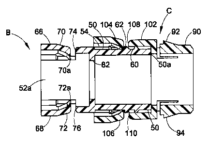
FIGS. 6-8 show a snap-in ENT adapter C having a cylindrical male end
portion 90 and a pair of resilient opposite snap fingers 92, 94. Cylindrical
end portion
90 is closely receivable through a circular hole in the wall of an outlet box
or the like,
and snap fingers 92, 94 snap through the hole for securing adapter C to the
box wall.
Adapter C has a female ENT socket portion 102 that has the same configuration
as
described with reference to reducer fitting B. Thus, ENT socket 102 has
opposite
resilient latch fingers 104, 106 that are the same as latch fingers 70, 72 and
project
into opposite openings 108, 110 in the peripheral wall of ENT socket 102.
Male end portion 50 on reducer fitting B is receivable in socket 102 on
adapter
C as shown in FIGS. 7 and 8, and ring 62 is shown locked behind latch fingers
104,
106 to prevent removal of male end portion 50 from within socket 102. Openings
108, 110 in the peripheral wall of socket 102 normally provide a possible path
for
entry of poured concrete into socket 102 where it may flow along the clearance
between the inner peripheral wall of the socket and the outer peripheral
surface of
male end portion 50 to enter the passage within the fittings.
CLI-1208740v1
CA 02499165 2007-12-05
27175-133
-4-
In the configuration of the present application, ring projection 60 provides a
barrier against the flow of concrete through openings 108, 110 to the interior
of the
fittings. Thus, ring projection 60 can have other configurations and does not
require
the same configuration as ring projection 62 when it is used solely as a
barrier against
the flow of concrete.
Sockets 102 may be of different depths, and ring projection 60 performs the
same locking function as ring proj ection 62 when used with a shallower
socket. In a
shallower socket, ring projection 60 locks behind latch fingers 104, 106 and
ring
projection 62 is on the opposite side of latch fingers 104, 106 from the
position shown
in FIG. 7. In that configuration, an additional projecting ring that forms a
barrier
against flow of concrete may be provided between ring projection 60 and the
terminal
end of male end portion 50.
It will be recognized that female socket 102 may be on a threaded adapter or
on a socket that is molded integrally with a box sidewall instead of being on
a snap-in
adapter. Fitting B is configured for transitioning from one size of ENT socket
to the
next smaller size. For example, socket 102 may be configured for receiving a
one
inch trade size ENT tube while it is desired or necessary to use three-quarter
inch
trade size ENT tube. Male end portion 50 is configured for locking reception
within
the one inch ENT socket while ENT socket 52a on fitting B is configured for
locking
reception of an end portion of a three-quarter inch corrugated ENT tube
therein.
Fitting B may be configured for transitioning from three-quarter inch to one-
half inch
and other sizes as well.
Socket 52a in fitting B is configured for receiving either a one-half inch or
a
three-quarter inch trade size ENT tube. It will be recognized that other sizes
also can
be provided. One-half inch trade size ENT tubing has an outside diameter of
0.832-
0.848 inches. Three-quarter inch trade size ENT tubing has an outside diameter
of
1.040-1.060 inches. One inch trade size ENT tubing has an outside diameter of
1.305-1.325 inches.
The length of male end portion 50 of fitting B from terminal end 50a to
shoulder 54 is not critical because shoulder 54 is so small that it passes
into a
CA 02499165 2005-03-01
-5-
conventional trade size ENT socket. However, when shoulder 54 is radially
larger so
that it will not pass into a conventional ENT socket, the length of male end
portion 50,
from shoulder 54 to terminal end 50a is approximately 0.940 inches.
Radial rear surface 60b on ring projection 60 is spaced approximately 0.260
inches from terminal end 50a. Radial rear surface 62b on ring projection 62 is
spaced
approximately 0.410 inches from terminal end 50a. Thus, projections 60, 62 are
located much closer to terminal end 50a than to shoulder 54.
Although the improvements of this application have been shown and described
with reference to a representative embodiment, it is obvious that alterations
and
modifications will occur to others skilled in the art upon the reading and
understanding of this disclosure. Therefore, it is to be understood that the
improvements may be practiced otherwise than as specifically described herein
while
remaining within the scope of the claims.
CLI-1208740v1