Language selection

Search

Patent 2499217 Summary

Third-party information liability

Some of the information on this Web page has been provided by external sources. The Government of Canada is not responsible for the accuracy, reliability or currency of the information supplied by external sources. Users wishing to rely upon this information should consult directly with the source of the information. Content provided by external sources is not subject to official languages, privacy and accessibility requirements.

Claims and Abstract availability

Any discrepancies in the text and image of the Claims and Abstract are due to differing posting times. Text of the Claims and Abstract are posted:

  • At the time the application is open to public inspection;
  • At the time of issue of the patent (grant).
(12) Patent Application: (11) CA 2499217
(54) English Title: SURGICAL TOOL FOR REMOVAL OF BRAIN STEM
(54) French Title: OUTIL CHIRURGICAL POUR L'ENLEVEMENT DU TRONC CEREBRAL
Status: Deemed Abandoned and Beyond the Period of Reinstatement - Pending Response to Notice of Disregarded Communication
Bibliographic Data
Abstracts

English Abstract


A method for extracting at least a sample of the brain stem of an
animal for testing is carried out using a metal tool having a tubular handle
portion of
the metal body and a part tubular operating portion of the metal body defining
a
blade and scoop, inserting the operating portion while holding the handle into
the
cranial cavity of the head of the animal through the foramen magnum, rotating
the
tool to sever the cranial nerves and withdrawing the tool with the brain stem
cradled
in the operating portion.


Claims

Note: Claims are shown in the official language in which they were submitted.

7
CLAIMS:
1. ~A tool for extracting at least a sample of the brain stem of an
animal for testing comprising:
a metal body;
the metal body being formed from a metal tube;
a handle portion of the metal body being tubular to define a circular
end face at one end of the metal body onto which hammering force can be
applied;
and an operating portion of the metal body defining a blade and scoop
for cutting the brain stem sample and carrying the brain stem sample from the
animal;
the operating portion being defined by cutting an part of the cylinder
defining the tube from the tube and along the length of the operating portion
up to an
end of the handle portion such that the operating portion is part cylindrical
and
integral with the handle part;
a part circular cutting end face of the operating portion and at least a
part of the length of the side edges extending from the end face toward the
handle
portion of the operating portion being sharpened to form a cutting edge.
2. ~The tool according to Claim 1 wherein the operating portion
tapers from the handle portion to the end face.
3. ~The tool according to Claim 1 wherein the operating portion
tapers from the handle portion to the end face such that at the end of the
handle
portion the operating portion subtends and angle of the order of 180 degrees
and at

8
the cutting end face the operating portion subtends and angle of the order of
120
degrees.
4. The tool according to Claim 1 wherein the side edges of the
operating portion are sharpened approximately half way from the end cutting
face to
the handle portion.
5. A method for extracting at least a sample of the brain stem of an
animal for testing comprising:
providing a metal body having;
the metal body being formed from a metal tube;
a handle portion of the metal body being tubular to define a
circular end face at one end of the metal body onto which hammering force can
be
applied;~
and an operating portion of the metal body defining a blade and
scoop for cutting the brain stem sample and carrying the brain stem sample
from the
animal;
the operating portion being defined by cutting an part of the
cylinder defining the tube from the tube and along the length of the operating
portion
up to an end of the handle portion such that the operating portion is part
cylindrical
and integral with the handle part;
a part circular cutting end face of the operating portion and at
least a part of the length of the side edges extending from the end face
toward the
handle portion of the operating portion being sharpened to form a cutting
edge;

9
inserting the operating portion while holding the handle into the cranial
cavity of the head of the animal through the foramen magnum;
rotating the tool to sever the cranial nerves;
and withdrawing the tool with the brain stem cradled in the operating
portion.
6. The method according to Claim 5 wherein the operating portion
tapers from the handle portion to the end face.
7. The method according to Claim 5 wherein the operating portion
tapers from the handle portion to the end face such that at the end of the
handle
portion the operating portion subtends and angle of the order of 180 degrees
and at
the cutting end face the operating portion subtends and angle of the order of
120
degrees.
8. The method according to Claim 5 wherein the side edges of the
operating portion are sharpened approximately half way from the end cutting
face to
the handle portion.

Description

Note: Descriptions are shown in the official language in which they were submitted.


r~9
CA 02499217 2005-03-03
SURGICAL TOOL FOR REMOVAL OF BRAlN STEM
This invention relates to a tool for removing the brain stem of an animal
for testing for example for BSE.
BACKGROUND OF THE INVENTION
In testing for various diseases in slaughtered animals, it is common
that samples are required. For testing for BSE, only the brain stem (most
importantly the obex) is required to be submit#ed for BSE diagnosis.
Typically the sample is removed using a post mortem knife in which
the head is disarticulated from the carcass at the atlanto-occipital joint.
The head is
oriented on a table or work surface with the dorsal side down and with the
foramen
magnum facing the operator. Using scissors and forceps, the dura matter is
removed through the foramen magnum opening to expose the medulla.
A brain knife is inserted into the cranial cavity through the foramen
magnum using a side to side slicing motion until a tip of the knife contacts
bone.
The knife blade is maintained parallel to the dorsal surface of the brain stem
but
ventral to the cerebellum. The knife blade is rotated and carefully pushed
aside the
cerebellum and the knife removed. A spatula is inserted through the foramen
magnum with the spatula blade facing laterally. The blade is pushed until the
staff of
the spatula is approximately 2/3 into the cranial cavity and the blade is
rotated
ventrally and then dorsally severing the brain stem. The cordal end of the
brain
stem is grasped using forceps and pulled with the spatula and the forceps thus
removing the brain stem.

CA 02499217 2005-03-03
2
A tool specifically designed for this process is shown in US Patent
application 2002/0002375 published January 23, 2002. This provides a spatula
formed of plastic with a handle and the spoon section with a sharpened leading
edge. The spoon has proven to be generally unsatisfactory and is unpopular
with
persons required to carry out this function. The spoon cannot operate on
frozen or
partially frozen heads due to the weakness of the plastics material, bearing
in mind
that the carcass can be frozen in many cases due to the surrounding cold
weather.
SUMMARY OF THE INVENTION
It is one object of the invention to provide an improved tool and method
for removing the brain stem of an animal for testing.
According to one aspect of the invention there is provided a tool for
extracting at least a sample of the brain stem of an animal for testing
comprising:
a metal body;
the metal body being formed from a metal tube;
a handle portion of the metal body being tubular to define a circular
end face at one end of the metal body onto which hammering force can be
applied;
and an operating portion of the metal body defining a blade and scoop
for cutting the brain stem sample and carrying the brain stem sample from the
animal;
the operating portion being defined by cutting an part of the cylinder
defining the tube from the tube and along the length of the operating portion
up to an
end of the handle portion such that the operating portion is part cylindrical
and

CA 02499217 2005-03-03
3
integral with the handle part;
a part circular cutting end face of the operating portion and at least a
part of the length of the side edges extending from the end face toward the
handle
portion of the operating portion being sharpened to form a cutting edge.
Preferably the operating portion tapers from the handle portion to the
end face.
Preferably the operating portion tapers from the handle portion to the
end face such that at the end of the handle portion the operating portion
subtends
and angle of the order of 180 degrees and at the cutting end face the
operating
portion subtends and angle of the order of 120 degrees.
Preferably the side edges of the operating portion are sharpened
approximately half way from the end cutting face to the handle portion.
According to a second aspect of the invention there is provided a
method for extracting at least a sample of the brain stem of an animal for
testing
comprising:
providing a metal body having;
the metal body being formed from a metal tube;
a handle portion of the metal body being tubular to define a circular
end face at one end of the metal body onto which hammering force can be
applied;
and an operating portion of the metal body defining a blade and scoop
for cutting the brain stem sample and carrying the brain stem sample from the
animal;

CA 02499217 2005-03-03
4
the operating portion being defined by cutting an part of the cylinder
defining the tube from the tube and along the length of the operating portion
up to an
end of the handle portion such that the operating portion is part cylindrical
and
integral with the handle part;
a part circular cutting end face of the operating portion and at least a
part of the length of the side edges extending from the end face toward the
handle
portion of the operating portion being sharpened to form a cutting edge;
inserting the operating portion while holding the handle into the cranial
cavity of the head of the animal through the foramen magnum;
rotating the tool to sever the cranial nerves;
and withdrawing the tool with the brain stem cradled in the operating
portion.
BRIEF DESCRIPTION OF THE DRAWINGS
One embodiment of the invention will now be described in conjunction
with the accompanying drawings in which:
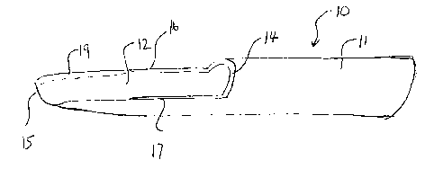
Figure 1 is an isometric view of a tool according to the present
invention.
Figure 2 is a top plan view of the tool of Figure 1.
Figure 3 is a side elevational view of the tool of Figure 1.
In the drawings like characters of reference indicate corresponding
parts in the different figures.

CA 02499217 2005-03-03
DETAILED DESCRIPTION
The tool according to the present invention is shown in Figures 1 2 and
3 and comprises a tubular body 10 including a handle portion 11 and an
operating
portion 12. The tubular body is cut from a single piece of pipe or tube of
stainless
5 steel or other suitable non corrosive metal so that the handle portion 11
and the
operating portion 12 are integral. The handle portion 11 forms a full
periphery of the
tubular member so that it is cylindrical in shape with a circular end face 13.
The
operating portion is formed by cutting partway across the tube to form a face
14
which is part circular and extends around approximately 180° of arc of
the tubular
member. From that face 14, a further cut extends along the tube from the face
14 to
an end cutting face 15 of the operating portion.
Thus the operating portion 12 is formed as a part cylindrical portion
which tapers slightly from 180° of arc at the face 14 to the end
cutting face 15 which
is arranged to be approximately 120° of arc.
Thus the cutting action forms two side edges 16 and 17 of the part
cylindrical portion which forms a scoop and a blade for the cutting action.
The edges
16 and 17 are then sharpened by grinding as indicated at 19 and 20 to form
sharpened edges along the sides 16 and 17 and through the cutting end face 15.
The sharpening action is applied on the inside surface so that the outside
surface is
sharp and forms a part cylindrical cutting blade extending approximately one
half
way along the operating portion to a mid line generally indicated at 21.
The tool is used on the head with the ventral side down such that the

CA 02499217 2005-03-03
6
foramen magnum is facing the operator. Using forceps and scissors, a single
cut is
made down the center of the exposed dura matter creating two flaps. Holding
the
dura mater with the forceps to expose the cranial nerves exiting the spinal
cord, the
cranial nerves are severed from the spinal cord thus freeing the spinal cord
and
facilitating the removal of the obex using the tool herein.
With the tool having the channel or receptacle facing downwardly, it is
inserted through the foramen magnum moving it forwardly and lodging the tip
between the cerebellum and the brain stem-spinal cord. Applying downward
pressure on the tool, it is moved from side to side as a rotating action over
the spinal
cord to sever it from the rest of the brain. The channel is used to pull the
severed
portion of the brain stem from the foramen magnum.
The tool with the metal sharp edges provides an effective cutting action
to ensure that the nerves are properly cut and the required part removed. Even
in a
frozen condition, the tool can be inserted and if necessary a hammering force
can be
applied onto the end face of the handle to drive the tool using the cutting
edge into
the required position.
Since various modifications can be made in my invention as herein
above described, and many apparently widely different embodiments of same made
within the spirit and scope of the claims without department from such spirit
and
scope, it is intended that all matter contained in the accompanying
specification shall
be interpreted as illustrative only and not in a limiting sense.

Representative Drawing
A single figure which represents the drawing illustrating the invention.
Administrative Status

2024-08-01:As part of the Next Generation Patents (NGP) transition, the Canadian Patents Database (CPD) now contains a more detailed Event History, which replicates the Event Log of our new back-office solution.

Please note that "Inactive:" events refers to events no longer in use in our new back-office solution.

For a clearer understanding of the status of the application/patent presented on this page, the site Disclaimer , as well as the definitions for Patent , Event History , Maintenance Fee  and Payment History  should be consulted.

Event History

Description Date
Application Not Reinstated by Deadline 2011-03-03
Time Limit for Reversal Expired 2011-03-03
Inactive: Abandon-RFE+Late fee unpaid-Correspondence sent 2010-03-03
Deemed Abandoned - Failure to Respond to Maintenance Fee Notice 2010-03-03
Small Entity Declaration Determined Compliant 2007-09-12
Inactive: Cover page published 2006-09-03
Application Published (Open to Public Inspection) 2006-09-03
Inactive: IPC assigned 2005-04-26
Inactive: First IPC assigned 2005-04-26
Application Received - Regular National 2005-04-07
Filing Requirements Determined Compliant 2005-04-07
Inactive: Filing certificate - No RFE (English) 2005-04-07

Abandonment History

Abandonment Date Reason Reinstatement Date
2010-03-03

Maintenance Fee

The last payment was received on 2009-01-30

Note : If the full payment has not been received on or before the date indicated, a further fee may be required which may be one of the following

  • the reinstatement fee;
  • the late payment fee; or
  • additional fee to reverse deemed expiry.

Please refer to the CIPO Patent Fees web page to see all current fee amounts.

Fee History

Fee Type Anniversary Year Due Date Paid Date
Application fee - small 2005-03-03
MF (application, 2nd anniv.) - small 02 2007-03-05 2007-01-22
MF (application, 3rd anniv.) - small 03 2008-03-03 2008-02-04
MF (application, 4th anniv.) - small 04 2009-03-03 2009-01-30
Owners on Record

Note: Records showing the ownership history in alphabetical order.

Current Owners on Record
ADRIEN GRENIER
Past Owners on Record
None
Past Owners that do not appear in the "Owners on Record" listing will appear in other documentation within the application.
Documents

To view selected files, please enter reCAPTCHA code :


To view images, click a link in the Document Description column. To download the documents, select one or more checkboxes in the first column and then click the "Download Selected in PDF format (Zip Archive)" or the "Download Selected as Single PDF" button.

List of published and non-published patent-specific documents on the CPD .

If you have any difficulty accessing content, you can call the Client Service Centre at 1-866-997-1936 or send them an e-mail at CIPO Client Service Centre.


Document
Description 
Date
(yyyy-mm-dd) 
Number of pages   Size of Image (KB) 
Description 2005-03-03 6 226
Abstract 2005-03-03 1 16
Drawings 2005-03-03 1 17
Claims 2005-03-03 3 92
Representative drawing 2006-08-08 1 4
Cover Page 2006-08-15 1 30
Filing Certificate (English) 2005-04-07 1 157
Reminder of maintenance fee due 2006-11-06 1 112
Reminder - Request for Examination 2009-11-04 1 117
Courtesy - Abandonment Letter (Maintenance Fee) 2010-04-28 1 171
Courtesy - Abandonment Letter (Request for Examination) 2010-06-09 1 165
Correspondence 2007-09-12 2 41