Note: Descriptions are shown in the official language in which they were submitted.
CA 02499746 2005-03-21
Anti-Interference Filter and Lightning Arrester Device
The invention relates to an anti-interference filter and lightning arrester
device in a
coaxial line for the transmission of high-frequency signals, comprising a
housing with
two connectors, the housing forming an outer conductor connected to ground, an
inner
conductor carried through the housing, a connection between inner conductor
and
housing for diverting overvoltages and a gas capsule diverter in the
connection
between inner conductor and housing.
Anti-interference filter and lightning arrester devices of this type are
known. They
serve for the purpose of protecting structural groupings, apparatus or
facilities
connected to lines, for example coaxial lines of telecommunication devices,
against
electromagnetic pulses (EMP), overvoltages and/or lightning currents.
Electromagnetic
pulses of artificial type can be generated for example by motors, switches,
clocked
power supplies or also in connection with nuclear events. Pulses of natural
origin can
result, for example, as a consequence of direct or indirect lightning strikes.
The known
protective circuits are disposed at the input side of the structural
groupings, apparatus
or facilities and/or are installed as a structural component in the coaxial
line.
An EMP diverter of this type with a gas capsule or gas discharge overvoltage
diverter is
known from CH 660 261 A5. This EMP diverter comprises a housing serving as
outer
conductor and connected to ground. Disposed at both ends of the housing are
connectors, by means of which the housing can be connected with one end each
of a
coaxial cable. Through the center of the housing is carried an inner conductor
which, in
the proximity of the connectors, can also be connected with the coaxial cable.
Radially
with respect to the inner conductor is disposed a housing portion, which
serves for
accommodating the overvoltage diverter in the form of a gas capsule. This
overvoltage
CA 02499746 2005-03-21
diverter is connected, on the one hand, to the inner conductor and, on the
other hand, to
the housing and therewith to ground. Gas capsule overvoltage diverters have
the
property that during normal operation their resistance is on the order of a
few GS2.
Upon reaching a specified ignition voltage, an electric flashover occurs and
the
resistance of the gas capsule jumps to values of less than 1SZ. This state
occurs in the
case of interference if, for example, on the antenna side, an overvoltage
occurs due to a
lightning strike. The gas capsule overvoltage diverter protects the elements
located on
the apparatus side by diverting the overvoltage low-ohmically to ground. After
the
decay of the overvoltage, the gas capsule becomes high-ohmic and returns to
the
normal operating state, i.e. it acts again as an isolation. During the time
interval in
which the gas capsule is low-ohmic, the so-called arc burning voltage is
connected to
the gas capsule. This burning voltage is on the order of a few 10 V. As long
as a current
of a few 10 mA flows, the arc discharge persists and the gas capsule remains
in the low-
ohmic state. This may occur for example if across the coaxial cable or the
anti-
interference filter and lightning arrester device an additional DC control
current is
conducted or in the presence of high-frequency signals of relatively high
power. In
these cases a device with a gas capsule diverter has the considerable
disadvantage that
after a response, for example due to a lightning strike, it is no longer
extinguished but
rather remains permanently in the low-ohmic state. To restore the normal
state, the DC
control current must in this case be switched off and/ or the high-frequency
signal must
be interrupted. Normally this requires switching off the particular facility
and switching
it on again, which entails considerable complications and/or is especially
undesirable in
communication facilities.
The aim of the present invention is to provide an anti-interference filter and
lightning
arrester device in which undesirable overvoltages are diverted to ground via a
gas
capsule diverter and in which it is ensured that the gas capsule diverter,
after the
suppression of the interference, in spite of the presence of DC voltage and/or
high-
frequency signals, changes from the conducting to the nonconducting state even
if the
o~
CA 02499746 2005-03-21
applied voltage is higher than the burning voltage of the gas capsule
diverter.
This aim is attained in connection with the preamble of patent claim 1 in
accordance
with the invention through the characterizing characteristics of patent claim
1.
Advantageous further developments of the invention follow from the
characteristics of
the dependent claims.
In the solution or device, respectively, according to the invention in the
connection for
diverting overvoltages between inner conductor and housing two gas capsule
diverters
are inserted in series. Between the two gas capsule diverters is located a
contact point,
and between this contact point and ground, a switching configuration is
disposed with
an interrupter element for interrupting a current flowing across the gas
capsule
diverter. This solution according to the invention permits the diverting of
interference
or overvoltages in that both series-connected gas capsule diverters are
ignited
sequentially and set up a connection between inner conductor and ground. After
the
overvoltages have been suppressed and if a voltage, which is higher than the
burning
voltage, continues to be present at the two gas capsule diverters, the voltage
at the
contact point between the two gas capsule diverters is reduced with the
switching
configuration so far that the second gas capsule directed to ground is
extinguished.
After extinguishing the second of the two gas capsules, the current flows
across the first
gas capsule and the contact point across the switching configuration to
ground. The
switching configuration now permits the interruption of this current flow
whereby the
first gas capsule diverter is also extinguished. Therewith the two gas capsule
diverters
can be reset from the conducting to the nonconducting state without the
control
voltages or high-frequency currents applied to the apparatus needing to be
interrupted.
This permits the completely automatic resetting of the anti-interference
filter and
lightning arrester into the normal state in which there is no conductive
connection
between inner conductor and ground. Resetting the two gas capsule diverters
from the
conducting to the nonconducting state can take place in a very short time,
such that,
3
CA 02499746 2005-03-21
after an interference event, the apparatus is immediately ready again for
operation.
An advantageous solution comprises that the switching configuration includes a
resistance element connected to the contact point, a voltage-limiting element
connected
in series with this resistance element, and a coil of a switching relay also
connected in
series with the resistance element, the voltage-limiting element and the coil
of the
switching relay being connected in parallel. The resistance element, which is
connected
directly with the contact point between the two gas capsule diverters, ensures
that,
upon the occurrence of an overvoltage, in a first phase the overvoltage is not
diverted
across the switching configuration to ground, but rather that the two gas
capsule
diverters are ignited successively and the overvoltage, or the overcurrent, in
a first
phase is diverted directly across the gas capsule diverters to ground. An
especially
suitable resistance element is for example an inductor. If, after the
suppression of the
interference voltage, there is still a voltage at the gas capsule diverters
which is higher
than the burning voltage and a corresponding current flows across the two gas
capsule
diverters, this current flows from the contact point also across the
resistance element,
for example in the form of an inductor, and the voltage-limiting element to
ground. A
suitable voltage-limiting element is for example a diode or a voltage
dependent resistor
(VDR). The voltage dependent element, for example in the form of a diode,
serves for
the purpose of protecting the inductor and the coil of the switching relay
against
undesirable interference states and to reduce the voltage to below the arc
burning
voltage of the gas capsule. However, the current flows simultaneously also
from a
branch point after the resistance element across the coil of the switching
relay. This
switching relay is a component of an interrupter element, which serves for
interrupting
the current flowing across the gas capsule diverter. For this purpose the
interrupter
element is advantageously implemented as an interrupter switch and is
installed in the
connection line after the resistance element. This interrupter switch is
connected with
the coil of the switching relay and is actuated by the same. The interrupter
switch is
installed in the connection line between the resistance element and the branch
point.
CA 02499746 2005-03-21
Upon the occurrence of an overvoltage, the two series-connected gas capsule
diverters
are ignited in succession as a consequence of the rapid rise of the voltage
and form a
conducting connection between the inner conductor and the housing or ground.
In the
conducting state of the two gas capsule diverters a burning voltage of 10 V,
for
example, is applied at the contact point between the two gas capsule
diverters, and in
front of the first gas capsule, a voltage of, for example, 20 V. This applies
if two
identical gas capsule diverters are employed and these gas capsule diverter
have each a
burning or arc voltage of 10 V in the conducting state. When there is no
longer a
overvoltage present and no additional voltage is connected to the apparatus,
the
voltage falls below the burning voltage of the gas capsule diverters and they
are
extinguished or switch from the conducting to the nonconducting state.
However, if,
after the suppression of the overvoltage, there is still a voltage at the
apparatus which is
higher than the burning voltage of the gas capsule diverters, they remain in
the
conducting state. If the residual current is the consequence of a DC control
voltage
applied to the apparatus, this current now flows also through the resistance
element, for
example an inductor, and via the voltage-limiting element, for example a
diode, to
ground. The series-connected inductor and the diode are therein selected such,
that the
voltage at the contact point between the two gas capsule diverters falls below
the
burning voltage, for example to 8 V, whereby the second gas capsule connected
to
ground is extinguished or reset to the nonconducting state. From the branch
point after
the resistance element, current also flows parallel to the voltage-limiting
element across
the coil of the interrupter element or of the switching relay. The coil is so
implemented
that the switching process takes place with a delay, this delay being selected
such, that,
first, the second gas capsule diverter is extinguished or reset to the
nonconducting state.
After the passage of this delay time, the switching relay actuates the
interrupter switch
and interrupts the connection line between the resistance element and the
branch point
or ground. Thereby the current flowing across the first gas capsule diverter
is also
interrupted and is also extinguished, i.e. it is reset to the nonconducting
state.
S
CA 02499746 2005-03-21
Disposing a decoupling line between the inner conductor and the first gas
capsule
diverter connected with the inner conductor has further advantages. These
comprise
that the two gas capsule diverters and the switching configuration are
decoupled from
high-frequency currents or signals. This decoupling line is tuned to the
frequency
transmitted across the coaxial line. This advantageous disposition of an
additional
decoupling line ensures that high-frequency signals with a voltage level above
the
burning voltage of the gas capsule diverter are not conducted into the
proximity of the
switching configuration. The decoupling line is implemented in a mariner known
per
se, for example as described in WO 99/43052 or EP 0 938166 A1. Suitable
decoupling
lines are 7~/4 lines or resonance circuits.
The interrupter element in the form of an interrupter switch associated with
the
switching configuration can also be installed directly in the inner conductor
and the
interrupter switch is in this case also directly connected with the coil of
the switching
relay and is actuated by it. This disposition is useful for example in
communication
devices with an antenna and a base station, the interrupter switch being
installed in the
inner conductor at the apparatus-end. By briefly interrupting the inner
conductor,
therewith control voltages or high-frequency signals with sufficiently high
power,
which are emitted by the base station, can be briefly interrupted in order for
the gas
capsules to be extinguished. In this solution the disposition of the gas
capsule diverters
and of the switching configuration are for the remainder implemented
identically to the
way described above.
In the following the invention will be described based on embodiment examples
with
reference to the enclosed drawing. Therein depict:
Fig.1 a device according to the invention with high-frequency (HF) decoupling
in partial section,
C
CA 02499746 2005-03-21
Fig. 2 a simplified equivalent circuit diagram of the device according to
figure 1,
and
Fig. 3 a simplified equivalent circuit diagram of a device according to the
invention without HF decoupling.
Fig. 1 represents an anti-interference filter and lightning arrester device
suitable as
insertion adapter for a coaxial cable into an structural apparatus component
in a
telecommunication device. At each end a housing 1 comprises in the direction
of a
longitudinal axis 18 a connector 2, 3. These connectors 2, 3 serve to connect
the ends of
coaxial cables with the device. Through an interior hollow space 19 of the
housing 1 is
guided an inner conductor 4, which is separated by insulators 20, 21 from
housing 1.
The housing 1 comprises a threaded joint 22, which serves for connecting the
device
with an apparatus wall or ground bar. A threaded bore 23 on housing 1 serves
for
fastening a ground conductor. In housing 1 is disposed a throughlet opening
24, in
which an additional housing 25 is fastened. This additional housing 25 is
comprised of
several housing parts 26, 27 and 28, but it can also be implemented as a
single part. The
first additional housing part 26 serves for receiving a decoupling line in the
form of a
~,/4 line 16 connected with the inner conductor 4 and branching off from it
approximately at right angles. This 7~/4 line 16 forms a first section of the
connection 5
between the inner conductor 4 and housing 1, which serves for diverting
overvoltages.
At the end 29, remote from the inner conductor 4, of the ~,/4 line 16 a
capacitor 30 as
well as a connecting element 31 is disposed. This connecting element 31 is
implemented
as a mounting for two gas capsule diverters 6, 7 and connected in conductance
with the
~,/4 line 16. The two gas capsule diverters 6, 7 are connected in series and
installed
approximately radially in the additional housing part 27.
Between the first gas capsule diverter 6 and the second gas capsule diverter 7
connected
in series with it, is developed a contact point 8 and the second gas capsule
diverter 7 is
CA 02499746 2005-03-21
connected via the closure screws 32 in conductance with the housing 1 or
ground.
Connected by means of line 33 with the contact point 8 between the two gas
capsule
diverters 6, 7 is a switching configuration 9. The switching configuration 9
is disposed
in the interior space of the additional housing part 28. The details with
respect to this
switching configuration 9 are shown in fig. 2 and described accordingly.
The decoupling line, or ~,/4 line 16 installed in this preferred solution,
serves for the
purpose of decoupling in a manner known per se the remaining diverter elements
from
the high-frequency signals on the inner conductor 4. Upon the occurrence of an
overvoltage, this overvoltage is diverted via the ~,/4 line 16 and the
connecting element
31 via the gas capsule diverters 6 and 7 to ground. This type of diverting of
overvoltages is known per se. In coaxial lines, across which DC control
voltages are
also transmitted whose voltage is higher than the burning voltage of the gas
capsule
diverters 6, 7, difficulties occur in the known solutions since the gas
capsule diverters 6,
7 are no longer reset to the nonconducting state when the overvoltage decays.
The
switching configuration 9 now serves for separating, first, the gas capsule
diverter 7 and
subsequently the gas capsule diverter 6 from the currents flowing and to
change them
to the nonconducting state.
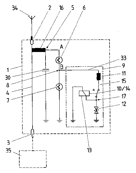
Fig. 2 shows a simplified equivalent circuit diagram for the device according
to the
invention in accordance with fig.1. The housing 1, which forms an outer
conductor,
and the inner conductor 4 are connected across the connectors 2, 3 and coaxial
lines
connected thereto, on the one hand, with an antenna 34 and, on the other hand,
with a
facility part or apparatus 35. To divert overvoltages and/or interference
voltages, a
connection 5 is disposed between the inner conductor 4 and the housing 1
connected to
ground, which connection 5 in the event of an interference protects the
facility part or
apparatus 35 and diverts corresponding interference voltages or currents. The
connection 5 is substantially comprised of three structural groups. A first
group
includes the decoupling line, or ~,/4 line 16, and the capacitor 30 connected
in series
CA 02499746 2005-03-21
with it, in order to short-circuit the high-frequency signals on the inner
conductor 16
with ground. The second group is connected in series with the ~,/4 line 16 and
comprises two series-connected gas capsule diverters 6 and 7. Between the
first of these
gas capsule diverters 6 and the second gas capsule diverter 7 is located a
contact point 8
with which the third structural group, the switching configuration 9, is
connected. In
line 33 extending from contact point 8, a resistance element in the form of an
inductor
11 is disposed and in series with this inductor 11 a voltage-limiting element
in the form
of a diode 12, as well as parallel to diode 12 via a branch point 17 a coil 13
of a switching
relay. In the connecting line 15 extending from inductor 11 in front of the
branch point
17 is installed an interrupter element 10 in the form of an interrupter switch
14. This
interrupter switch 14 is actuated by coil 13. In the normal state the
interrupter switch 14
is closed, i.e. a current can flow from contact point 8 via line 33, inductor
11, connection
line 15 and via the branch point 17 via diode 12 and coil 13 to ground. In the
depicted
example the diode 12 is a TVS diode, this diode 12 essentially protecting the
coil 13 of
the switching relay and being responsible for the voltage at contact point 8
being
decreased below the arc burning voltage of capsule 7. With the depicted device
according to the invention an effective protection of facility parts 35
against interference
and overvoltages, for example lightning strikes, is ensured when utilizing gas
capsule
diverters. The gas capsule diverters 6, 7 can automatically be reset to the
nonconducting state after an overvoltage has been diverted even if on the
coaxial line,
or the inner conductor 4, DC control voltages or high-frequency signals are
present
whose voltage is higher than the burning voltage of the gas capsule diverters
6 and 7.
The depicted anti-interference filter and lightning arrester device functions
in the
following manner. If, for example, due to a lightning strike via the antenna
34 at
connector 2 of housing 1 an overvoltage occurs, this overvoltage is conducted
via the
~,/4 line 16 into connection 5. At point A in front of the gas capsule
diverter 6 the
voltage increases very rapidly and at approximately 700 V this gas capsule
diverter 6
ignites. At the succeeding point B, i.e. in front of gas capsule diverter 7,
the voltage
9
CA 02499746 2005-03-21
therewith also increases immediately and the gas capsule diverter 7 also
ignites. Via the
two conducting gas capsule diverters 6 and 7 the overvoltage is immediately
diverted
to ground. During the diverting process a voltage of approximately 20 V is
present at
point A, which corresponds to the twofold burning voltage, and at point B a
voltage of
approximately 10 V. Via line 33 branching off from point B, or from contact
point 8, and
therewith via the inductor 11 current does not yet flow since the voltage rise
is too fast.
As soon as the lightning strike has past and the overvoltage breaks down and a
DC
control voltage is present, however, at the inner conductor 4 the DC control
voltage is
still present. If it is higher than the burning voltage of the gas capsule
diverters 6 and 7
these continue to remain in the conducting state. In the case of the devices
known until
now, the control current had to be switched off, in order to extinguish the
gas capsule
diverters 6, 7. According to the present invention this is no longer necessary
since at
constant voltage at contact point 8 now also current flows off via the
inductor 11 and
the diode 12. This leads to a voltage breakdown at contact point 8, or point
B, to
approximately 8 V, with the consequence that the second gas capsule diverter 7
is
extinguished and is reset to the conducting state. However, simultaneously in
switching configuration 9 a current also flows from branch point 17 via the
coil 13 of the
switching relay. This coil 13 has a switching delay of a few milliseconds, for
example of
3 milliseconds, until the interrupter element 10, or the interrupter switch
14, is actuated.
As soon as the interrupter switch 14 is opened, the current flow through line
33 and
therewith through connection 5 is interrupted. As a consequence the gas
capsule
diverter 6 is also extinguished and is reset to the nonconducting state. As
soon as no
current flows any longer in the connecting line 33, the coil 13 is deactivated
and the
interrupter switch 14 closes again. Therewith the entire configuration is
again in the
normal state and is automatically ready again for further interference cases.
Fig. 3 shows a further variant of the device according to the invention in a
simplified
equivalent circuit diagram. In this configuration the connection 5, and
therewith the
switching configuration 9, is not decoupled from the high-frequency signals.
Therefore
I -0
CA 02499746 2005-03-21
connection 5 between inner conductor 4 and housing 1 in this embodiment
comprises
only two structural groups. The first structural group comprises the two
series-
connected gas capsule diverters 6 and 7, which ensure the diverting of
overcurrents to
ground. The second structural group comprises the elements disposed with line
33
between contact point 8 and ground. In line 33, again, a resistance element in
the form
of an inductor 11 is disposed and in series with it a diode 12. Via the branch
point 17 is
disposed in parallel to diode 12 the coil 13 of a switching relay. Via this
coil 13 the
interrupter element 10 in the form of an interrupter switch 14' is actuated.
This
interrupter switch 14' is installed in the inner conductor 4, and it is closed
in the normal
state. If in this configuration, due to an overvoltage, the two gas capsule
diverters 6 and
7 are ignited and the overvoltage is diverted to ground, in this case after
the
suppression of the overvoltage the inner conductor 4 must be briefly
interrupted in
order to ensure the extinguishing of the two gas capsule diverters 6, 7 in
every case. In
this embodiment the actuation of the switch 14' also takes place automatically
and the
latter is immediately, after the gas capsule diverter 6 is extinguished, reset
again to the
closed state. These switching processes occur within milliseconds, which is
the reason
for their being safe for the operation of the facility. Except for the
disposition of the
interrupter switch 14' and the absent high-frequency decoupling, the function
of this
embodiment corresponds to that described in connection with fig. 2.