Note: Descriptions are shown in the official language in which they were submitted.
CA 02499781 2007-04-05
Food transport container
The present invention relates to a food transport container, which comprises
an air circulation device, by means of which air is taken in from the interior
of the food transport container and blown out into the interior of the food
transport container, wherein the air circulation device comprises at least one
fan.
Such food transport containers are known from the background art.
In the known food transport containers of this type, the fan of the air
circulation device takes in the air directly from the interior of the food
transport container, with the result that dirt particles and other impurities
pass from the interior of the food transport container into the fan and lead
to
rapid fouling thereof.
The underlying object of the present invention is to provide a food transport
container of the initially described type that has a longer maintenance-free
operating period and/or a longer useful life.
In a food transport container
this object is achieved according to the invention in that the air circulation
device comprises at least one air intake channel, through which the air Is
taken in by the fan indirectly from the interior of the food transport
container.
The fact, that the air from the interior of the food transport container is
not
sucked directly Into the fan, but is taken in indirectly through the air
intake
channel, prevents dirt particles and other impurities from the interior of the
food transport container being able to come into direct contact with the fan.
Rather, such dirt particles and other impurities are previously separated from
the air stream in the air intake channel. The maintenance-free operating
period and/or the useful life of the moving components of the air circulation
device, in particular of an impeller of the fan, are therefore markedly
extended.
CA 02499781 2005-03-03
2
In a preferred development of the invention, it is provided that the air
circulation device comprises a cover having at least one intake opening,
through which air is drawn from the interior of the food transport container
into the air intake channel.
This cover may, in particular, take the form of a cover plate.
So that as many of the particles entrained by the air stream as possible are
separated from the air stream before the air stream reaches the fan, it is
advantageous when the air in the air intake channel is deflected from its
original inflow direction.
It is particularly advantageous when the air in the air intake channel is
deflected at least twice.
A particularly good separation of particles from the intake air stream is
achieved when the air intake channel is designed as an air labyrinth.
In a preferred development of the invention, it is provided that the air
intake
channel comprises an air-collecting portion and an air-forwarding portion
situated, in the air flow direction, downstream of the air-collecting portion.
This air-forwarding portion may in particular have a smaller air flow cross
section than the air-collecting portion.
The air intake channel may be formed particularly easily when the food
transport container comprises an outer shell and an inner shell, between
which a heat-insulating material is disposed, and that at least one region of
the side of the inner shell remote from the outer shell forms a boundary of
the air intake channel.
CA 02499781 2005-03-03
3
Furthermore, the air intake channel may be manufactured particularly easily
when the fan is disposed in a housing and at least one region of the housing
forms a boundary of the air intake channel.
It is particularly advantageous when the air intake channel comprises a
portion that is disposed at the rear of the fan remote from the interior of
the
food transport container. The effect thereby achieved is that the air stream
is drawn into the fan from the rear of the fan, for which purpose the intake
air stream is deflected at least once from its original flow direction.
It may further be provided that the air circulation device comprises a fan
grille having a plurality of air through-openings, through which air is drawn
from the air intake channel into the fan.
This fan grille may in particular be disposed at the rear of the fan remote
from the interior of the food transport container.
In a preferred development of the invention, the fan takes the form of a
radial fan, which takes in the air in axial direction and blows out the air in
radial direction.
In a preferred development of the invention, it is provided that the fan blows
out the intake air, not directly into the interior of the food transport
container, but into an air blow-out channel of the air circulation device.
This air blow-out channel may at at least one blow-out aperture open out
into the interior of the food transport container.
In order that the food and food containers disposed in the interior of the
food
transport container may be brought to a desired temperature and/or
maintained at a desired temperature, it is advantageous if the air circulation
device comprises at least one temperature control device for heating or
cooling the intake air. By means of the thus temperature-controlled,
CA 02499781 2005-03-03
4
circulated air the temperature of the food containers disposed in the interior
of the food transport container may be indirectly controlled.
Such a temperature control device may in particular comprise an electrical
resistance heating device.
When the fan blows out the intake air into an air blow-out channel, it is
preferably provided that the temperature control device heats or cools the
air situated in the air blow-out channel.
The air circulation device may, in principle, be disposed at any desired point
of the food transport container.
However, the air circulation device is preferably disposed on a door of the
food transport container that is used to close a loading and unloading
aperture of the food transport container.
Further features and advantages of the invention are the subject matter of
the following description and of the graphic representation of an
embodiment.
The drawings show:
Fig. 1 a diagrammatic perspective view of a food transport container, which
is closed at its front by a door;
Fig. 2 a diagrammatic perspective view of the food transport container
of Fig. 1, with the door open;
Fig. 3 a diagrammatic vertical longitudinal section through the food
transport container of Fig. 1;
CA 02499781 2005-03-03
Fig. 4 an enlarged view of the region I of Fig. 3;
Fig. 5 an enlarged view of the region II of Fig. 3;
5 Fig. 6 a diagrammatic horizontal longitudinal section through the food
transport container of Fig. 1;
Fig. 7 an enlarged view of the region III of Fig. 6;
Fig. 8 a diagrammatic perspective view of the door of the food transport
container of Fig. 1, viewed from the outside of the door;
Fig. 9 a diagrammatic perspective view of the door of the food transport
container, viewed from the inside of the door;
Fig. 10 a diagrammatic plan view of the inside of the door of Fig. 9,
wherein a cover plate of an air circulation device accommodated
in the door is partially broken away; and
Fig. 11 a diagrammatic plan view of a fan grille of a fan of the air
circulation device.
In all of the drawings, identical or functionally equivalent elements are
denoted by the same reference characters.
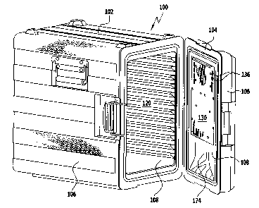
A food transport container, which is illustrated in Figs. 1 to 11 and denoted
as a whole by 100, comprises a substantially cuboidal container carcass 102,
which at its front has a loading and unloading aperture that is closable by
means of a door 104.
Both the container carcass 102 and the door 104 comprise in each case an
outer shell 106 and an inner shell 108, which are connected to one another
CA 02499781 2005-03-03
6
in such a way as to form between them a liquid-tight intermediate space 110
(see, for example, Figs. 4 and 5).
The outer shell 106 may be formed from any desired material, e.g. from a
metal material, in particular special steel, or from a plastics material, in
particular polypropylene.
The inner shell 108 may be formed likewise from a plastics material,
preferably from polypropylene.
The intermediate space 110 between the outer shell 106, on the one hand,
and the inner shell 108, on the other hand, is filled with a heat-insulating
material. This heat-insulating material may be a plastics foam, in particular
a polyurethane foam.
The inner shell 108 of the container carcass 102, like the outer shell 106 of
the container carcass 102, comprises five walls, namely two mutually
opposite vertical side walls 112, a vertical back wall 114, a bottom wall 116
and a top wall 118.
Each of the side walls 112 of the inner shell 108 of the container carcass 102
is provided at its inner side facing the interior 120 of the food transport
container 100 with a series of horizontally extending and vertically mutually
spaced-apart ribs 122 (see Figs. 3 and 4), which form supports for trays,
racks or standard food containers, which are insertable through the loading
and unloading aperture into the container carcass 102.
As may best be seen from Figs. 9 and 10, the inner shell 108 of the door 104
of the food transport container 100 is provided at its side facing the
interior
120 with a recess 124 for receiving a heating module, which is denoted as a
whole by 126.
CA 02499781 2005-03-03
7
The heating module 126 and the intermediate space 128 left between the
inner shell 108 and the heating module 126 are covered in the direction of
the interior 120 of the food transport container 100 by a substantially
rectangular cover plate 130, which is fastened by a plurality of fastening
screws 132 to the inner shell 108 as well as to a housing 134 of the heating
module 126.
The upper half of the cover plate 130 is provided with a plurality of intake
openings 136, which take the form of slot-shaped oblong holes and are
arranged in three rows, namely in two side rows 138a, 138b along the side
edges and in a middle row 140 along the top edge of the cover plate 130.
The intake openings 136 open out at the side of the cover plate 130 remote
from the interior 120 of the food transport container 100 into an air-
collecting portion 142 of an air intake channel denoted as a whole by 144,
which is formed between the inner shell 108, on the one hand, and the
housing 134 of the heating module 126 as well as the cover plate 130, on
the other hand.
The air-collecting portion 142 of this air intake channel 144 surrounds the
housing 134 of the heating module 126 at the upper side thereof and at the
left and right side thereof and is delimited in an upward direction and in the
direction of its sides by a peripheral wall 146 of the recess 124 that forms
part of the inner shell 108, in the direction of the centre of the door 104 by
the housing 134 of the heating module 126, in the direction of the interior
120 of the food transport container 100 by the cover plate 130 and in the
direction of the outside of the door 104 by a back wall 148 of the recess 124
that likewise forms part of the inner shell 108.
The rear part of the air-collecting portion 142 remote from the cover plate
130 opens out at its radially inner edge (i.e. the edge facing the centre of
the
door) into an air-forwarding portion 150 of the air intake channel 144 that is
delimited, on the one hand, by the back wall 148 of the recess 124 and, on
CA 02499781 2005-03-03
8
the other hand, by a back wall 152 of the housing 134 of the heating module
126.
This air-forwarding portion 150 has a smaller air flow cross section than the
air-collecting portion 142.
The air-forwarding portion 150 is delimited in a downward direction by a
projection 153, which projects from the back wall 152 of the housing 134 of
the heating module 126 in the direction of the inner shell 108 and rests
against the inner shell 108 (see Fig. 4).
Part of the back wall 152 of the housing 134 of the heating module 126 is
formed by the fan grille 154, which is shown in plan view in Fig. 11 and
comprises a plurality of, e.g. eight, radial webs 156 as well as a plurality
of,
e.g. three, circular webs 158, which cut the radial webs 156 in each case at
right angles, wherein between the radial webs 156 and the circular webs 158
air through-openings 160 of the fan grille 154 are formed.
As may best be seen from Figs. 4 and 7, in the housing 134 of the heating
module 126 an impeller 162 of a fan 164 is rotatably supported and aligned
coaxially with the fan grille 154. The impeller 162 comprises a central,
substantially cylindrical hub 166 and fan blades 168 projecting from the
peripheral surface of the hub 166.
The fan 164 takes the form of a radial fan, which takes in air in axial
direction through the fan grille 154 and blows out air in radial direction
down
into a heating shaft 170 of the heating module 126 that adjoins the fan 164
in a downward direction.
In the heating shaft 170 heating elements 172, e.g. resistance wires of an
electrical resistance heating device, are disposed and, when the heating
CA 02499781 2005-03-03
9
device is switched on, heat the air flowing from top to bottom through the
heating shaft 170.
As may best be seen from Figs. 9 and 10, the heating shaft 170 at its end
remote from the fan 164 opens out into the bottom part of the recess 124 in
the inner shell 108 of the door 104, which bottom part forms a blow-out
funnel 174 for the air emerging from the heating shaft 170.
The heating shaft 170 and the blow-out funnel 174 together form an air
blow-out channel 176.
The air intake channel 144, the fan 164, the heating device with the heating
shaft 170, and the air blow-out channel 176 together form an air circulation
device 178 of the food transport container 100.
In the heating mode of the food transport container 100, in which mode the
food accommodated in the food transport container 100 is to be heated or
kept warm, this air circulation device 178 operates as follows:
By means of the fan 164, which has been set in operation, air from the
interior 120 of the food transport container 100 is sucked through the intake
openings 136 in the cover plate 130 of the door 104 into the air-collecting
portion 142 of the air intake channel 144.
The direction of flow of the air through the air circulation device 178 is
indicated in the drawings by the arrows 180.
The air, which initially flows substantially at right angles to the cover
plate
130 into the air-collecting portion 142, is deflected by the back wall 148 of
the recess 124 in such a way that the air flows substantially radially inwards
into the air-forwarding portion 150 of the air intake channel 144 and
therefore passes into the region of the air intake channel 144 that is
situated
CA 02499781 2005-03-03
(viewed from the interior 120 of the food transport container 100) behind
the fan 164.
From the air-forwarding portion 150, in which the air flows in substantially
5 radial direction, the air is deflected by the suction force of the fan 164
into
the axial direction 182 of the fan 164 and is sucked through the air through-
openings 160 of the fan grille 154 into the fan 164.
The impeller 162 of the fan 164 blows out the air, which has been taken in in
10 axial direction, in radial direction into the heating shaft 170.
When the heating device is switched on, the air flowing through the heating
shaft 170 is heated by the heating elements 172.
The air that is blown out of the bottom end of the heating shaft 170 into the
blow-out funnel 174 passes through the blow-out funnel 174 back into the
interior 120 of the food transport container 100, where it heats the food
containers and food accommodated in the food transport container 100.
Because the air from the interior 120 of the food transport container 100 is
sucked, not directly into the fan 164, but indirectly through the air intake
channel 144, wherein the air is deflected a plurality of times in the air
intake
channel 144 designed as an air labyrinth, dirt particles and other impurities
from the interior 120 of the food transport container 100 are prevented from
being able to come into direct contact with the fan 164. Rather, such dirt
particles and other impurities are previously separated from the air stream in
the air-collecting portion 142 of the air intake channel 144. The useful life
of
the moving components of the air circulation device 178, in particular of the
impeller 162, is therefore markedly extended.