Language selection

Search

Patent 2500155 Summary

Third-party information liability

Some of the information on this Web page has been provided by external sources. The Government of Canada is not responsible for the accuracy, reliability or currency of the information supplied by external sources. Users wishing to rely upon this information should consult directly with the source of the information. Content provided by external sources is not subject to official languages, privacy and accessibility requirements.

Claims and Abstract availability

Any discrepancies in the text and image of the Claims and Abstract are due to differing posting times. Text of the Claims and Abstract are posted:

  • At the time the application is open to public inspection;
  • At the time of issue of the patent (grant).
(12) Patent Application: (11) CA 2500155
(54) English Title: PERCUSSION ADAPTOR FOR POSITIVE DISPLACEMENT MOTORS
(54) French Title: ADAPTATEUR A PERCUSSION POUR MOTEURS VOLUMETRIQUES
Status: Deemed Abandoned and Beyond the Period of Reinstatement - Pending Response to Notice of Disregarded Communication
Bibliographic Data
Abstracts

English Abstract


Positive Displacement Motors (PDM) are widely used in the oil and gas industry
as an
adjunct for drilling a hole in earthen formations. The PDM uses pressure and
flow of the
drilling fluid to turn a rotor within a stator. The rotor then turns a drill
bit which removes
earthen cuttings, creating the hole. The drilling fluid then captures the
earthen cuttings
and removes them from the hole. When drilling with a PDM, the drill string
does not
have to be rotated to drill (as is the case with conventional drilling) and
this allows the
drill string to be oriented - resulting in directional drilling.
If one could add a percussive force to the drill bit on the PDM, the drilling
rate of
penetration could be significantly increased, the required weight on bit could
be
significantly reduced and torque required to turn the drill bit could be
significantly
reduced. All in all, a "percussionized" PDM would be a far more efficient
drilling tool.


Claims

Note: Claims are shown in the official language in which they were submitted.

Claims
The embodiments of the invention in which an exclusive property is claimed are
defined
as follows:
1. The activation of the piston. which provides the percussive effect, is via
the rotary
motion of the torque tube 4. No percussive devices currently use this method
of
piston activation.
2. The Percussion Adaptor becomes an integral part of the Positive
Displacement
Motor (PDM). The torque tube 4 becomes a physical extension of the PDM rotor,
rotating the drill bit and providing drilling fluid under pressure for
activation of
the piston 7. This is a new and unique design.

Description

Note: Descriptions are shown in the official language in which they were submitted.


CA 02500155 2005-03-14
Disclosure
This invention relates to the use of a Positive Displacement Motor (PDM) for
boring
earthen holes.
It has been well documented that providing a percussion force to a rotating
drill bit will
make the drill bit drill faster. The percussive force helps to break away
portions of the
drilled formation.
When drilling in hard earthen formations with a PDM, one must place a great
deal of
weight on the drill bit in order to break away pieces of formation and create
a drilled
hole. The placement of excessive weight on the drill bit causes the following
problems:
1. Potential to stall the PDM rotor, with a stoppage of drilling.
2. Potential to deviate from the expected wellbore, as the PDM follows
formation
planes.
~. Potential to create more torque in the drill string, making it difficult to
orient the
drill bit.
4. Potential to shorten the useful life of the PDM itself due to greater
pressures
within the PDNI components.
Bv adding a percussive force to the drill bit, the PDM could operate with
significantly
less weight on the drill bit. thus alleviating the above problems.

CA 02500155 2005-03-14
The rate of penetration (ROP) of a drilling device has a direct bearing on the
economics
of a drilling operation. A modern drilling rig with all its associated
services can be a
hugely expensive operation. It is very obvious that if a PDM operating in a
percussion
mode, could drill significantly faster than a conventional PDM, the economic
savings
could also be significant.
The invention described herewith is called a "Percussion Adaptor for Positive
Displacement Motors". In drawings which illustrate embodiments of the
invention,
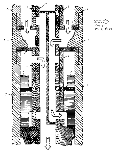
Figures 1, 2a, 2b, 3 and 4 show longitudinal sectional views of the Percussion
Adaptor
for Positive Displacement Motors.
The tool comprises an upper casing l, lower casing 2 and casing connector 3
which form
the outer body of the tool. The upper casing 1 is threaded into the lower
portion of a
PDM, which is modified to accept the upper casing threaded area.
Within the casings there is a torque tube 4, which transmits the torque from
the PDM
rotor to a drill bit, which is fastened by threads to the bottom of the torque
tube 4. The
torque tube 4 is connected to the PDM rotor via a sliding spline on the upper
end of the
torque tube 4. The spline arrangement allows longitudinal motion of the torque
tube 4
within the casings 1,2,3 , which is essential to the operation of the
Percussion Adaptor.
The longitudinal motion of the torque tube 4 is limited by a drive sub 8,
which is threaded
into the lower casing 2. In addition, the drive sub 8 acts as a bearing
surface for the
rotating torque tube 4.
The tool further includes a sliding piston 7, which is able to impart blows to
the lower
end of the torque tube 4. The energy of the blows is then transferred to a
drill bit which
is threaded into the lowest end of the torque tube 4. The outer surface of the
piston slides
within the confines of the lower casing 2, while the inner surface of the
piston slides
along the piston liner 6. The piston liner 6 is held in place by the threaded
junction of the
lower casing 2 and the casing connector 3.
The torque tube 4 is further stabilized by the upper torque tube bearing 5.
The upper
torque tube bearing 5 is held in place by the threaded junction of the upper
casing l and
the casing connector 3. The piston liner 6 is also a bearing surface for the
torque tube 4.
The upper torque tube bearing 5, piston liner 6, and torque tube 4 are all
ported to allow
the flow of drilling fluids under pressure. The specific arrangement of these
ports allow
for the required passage of drilling fluid to activate the piston into a
reciprocating motion,
providing the impact blows to the lower portion of the torque tube 4.
Whenever drilling fluid is circulating through the Percussion Adaptor, the
torque tube 4
will be necessarily rotating because of the action of the PDM. It is the
longitudinal
position of the torque tube 4 which is critical to percussion action of the
piston 7. When
there is no weight on the PDM and Percussion Adaptor, the tool is in a
"circulation only"
mode, as demonstrated in Figure 4. In this mode, the drilling fluid passes
through the

CA 02500155 2005-03-14
upper torque tube bearing 5 and into the torque tube :~ and then passes
strai~~ht throu'.rh
the torque tube -1 and out through the drill bit. There is no piston motion in
this mode.
Typically this mode is used for tlushin~~ cuttings out the wellbore with the
circulation of
the drilling fluid.
When the PDM and Percussion Adaptor are "on bottom" with weight applied. the
torque
tube =1 moves longitudinally upward. as shown in Figure 2a. In this mode. the
drilling
fluid is now routed into the torque tube 4 through a different port, which
causes the
drilling fluid to enter the bottom of the piston chamber, forcing the piston 7
upward. The
drilling fluid above the piston is vented into a different passageway in the
torque tube and
is expelled through the drill bit.
As the torque tube 4 rotates, the drilling fluid now is forced into the upper
piston chamber
(see Figure 2b) causes the piston to be forced down to strike the torque tube
~. The
drilling fluid below the piston is evacuated to the torque tube 4 and out
through the drill
bit. As the torque tube 4 further rotates, the cycle repeats itself and the
piston
reciprocates, providing a percussive force through the torque tube 4 to the
drill bit.
When the PDM and Percussion Adaptor are lifted off bottom, the torque tube 4
drops
longitudinally and the circulation mode, as shown in Figure 4, is restored.

Representative Drawing
A single figure which represents the drawing illustrating the invention.
Administrative Status

2024-08-01:As part of the Next Generation Patents (NGP) transition, the Canadian Patents Database (CPD) now contains a more detailed Event History, which replicates the Event Log of our new back-office solution.

Please note that "Inactive:" events refers to events no longer in use in our new back-office solution.

For a clearer understanding of the status of the application/patent presented on this page, the site Disclaimer , as well as the definitions for Patent , Event History , Maintenance Fee  and Payment History  should be consulted.

Event History

Description Date
Application Not Reinstated by Deadline 2006-12-04
Inactive: Dead - No reply to s.30(2) Rules requisition 2006-12-04
Application Published (Open to Public Inspection) 2006-09-14
Inactive: Cover page published 2006-09-13
Inactive: Abandoned - No reply to s.30(2) Rules requisition 2005-12-02
Inactive: S.30(2) Rules - Examiner requisition 2005-06-02
Inactive: IPC assigned 2005-05-24
Inactive: IPC removed 2005-05-24
Inactive: First IPC assigned 2005-05-24
Letter Sent 2005-05-11
Request for Examination Requirements Determined Compliant 2005-05-03
All Requirements for Examination Determined Compliant 2005-05-03
Request for Examination Received 2005-05-03
Inactive: IPC assigned 2005-04-29
Inactive: First IPC assigned 2005-04-29
Inactive: IPC assigned 2005-04-29
Inactive: Office letter 2005-04-19
Inactive: Filing certificate - No RFE (English) 2005-04-14
Filing Requirements Determined Compliant 2005-04-14
Application Received - Regular National 2005-04-14

Abandonment History

There is no abandonment history.

Fee History

Fee Type Anniversary Year Due Date Paid Date
Application fee - small 2005-03-14
Request for examination - small 2005-05-03
Owners on Record

Note: Records showing the ownership history in alphabetical order.

Current Owners on Record
DALE G. CROOKS
Past Owners on Record
None
Past Owners that do not appear in the "Owners on Record" listing will appear in other documentation within the application.
Documents

To view selected files, please enter reCAPTCHA code :


To view images, click a link in the Document Description column. To download the documents, select one or more checkboxes in the first column and then click the "Download Selected in PDF format (Zip Archive)" or the "Download Selected as Single PDF" button.

List of published and non-published patent-specific documents on the CPD .

If you have any difficulty accessing content, you can call the Client Service Centre at 1-866-997-1936 or send them an e-mail at CIPO Client Service Centre.


Document
Description 
Date
(yyyy-mm-dd) 
Number of pages   Size of Image (KB) 
Description 2005-03-13 3 138
Abstract 2005-03-13 1 24
Drawings 2005-03-13 5 347
Claims 2005-03-13 1 16
Representative drawing 2006-01-22 1 28
Acknowledgement of Request for Examination 2005-05-10 1 176
Filing Certificate (English) 2005-04-13 1 157
Courtesy - Abandonment Letter (R30(2)) 2006-02-12 1 166
Notice: Maintenance Fee Reminder 2006-12-17 1 120
Correspondence 2005-04-13 1 9
Fees 2006-12-17 2 71