Language selection

Search

Patent 2500544 Summary

Third-party information liability

Some of the information on this Web page has been provided by external sources. The Government of Canada is not responsible for the accuracy, reliability or currency of the information supplied by external sources. Users wishing to rely upon this information should consult directly with the source of the information. Content provided by external sources is not subject to official languages, privacy and accessibility requirements.

Claims and Abstract availability

Any discrepancies in the text and image of the Claims and Abstract are due to differing posting times. Text of the Claims and Abstract are posted:

  • At the time the application is open to public inspection;
  • At the time of issue of the patent (grant).
(12) Patent Application: (11) CA 2500544
(54) English Title: DECORATIVE LIGHT PANEL AND SUPPORT ASSEMBLY
(54) French Title: ENSEMBLE PANNEAU LUMINEUX DECORATIF ET SON SUPPORT
Status: Deemed Abandoned and Beyond the Period of Reinstatement - Pending Response to Notice of Disregarded Communication
Bibliographic Data
(51) International Patent Classification (IPC):
  • F21V 3/06 (2018.01)
  • E04B 9/04 (2006.01)
  • E04B 9/18 (2006.01)
  • E04B 9/32 (2006.01)
  • F21V 17/10 (2006.01)
  • G09F 13/04 (2006.01)
  • G09F 19/12 (2006.01)
(72) Inventors :
  • MIAN, ALEC (Spain)
  • CALLAHAN, JULIE (United States of America)
(73) Owners :
  • LA EVOLUCION BARCELONA, S.L.
(71) Applicants :
  • LA EVOLUCION BARCELONA, S.L. (Spain)
(74) Agent: ROBIC AGENCE PI S.E.C./ROBIC IP AGENCY LP
(74) Associate agent:
(45) Issued:
(86) PCT Filing Date: 2003-10-01
(87) Open to Public Inspection: 2004-04-15
Availability of licence: N/A
Dedicated to the Public: N/A
(25) Language of filing: English

Patent Cooperation Treaty (PCT): Yes
(86) PCT Filing Number: PCT/ES2003/000495
(87) International Publication Number: WO 2004032102
(85) National Entry: 2005-03-30

(30) Application Priority Data:
Application No. Country/Territory Date
200202237 (Spain) 2002-10-02

Abstracts

English Abstract


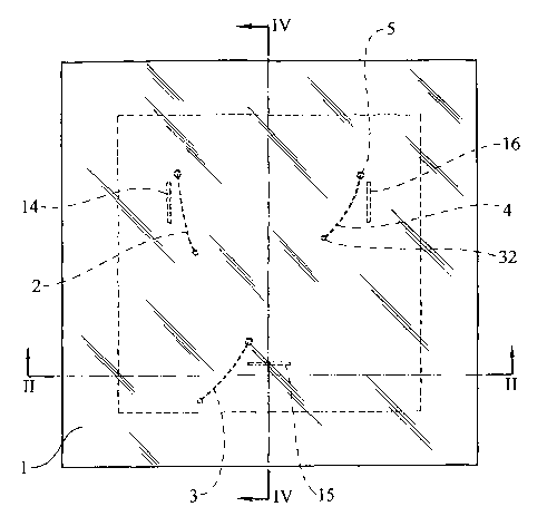
The invention relates to a decorative light panel and support assembly.
According to the invention, the panel, which is made from a translucent
synthetic material comprising decorative patterns, can receive the light from
a light source which is built into the support. Moreover, the aforementioned
panel comprises various different wire elements which are made from a
transparent material. One end of said wire elements is fixed to the rear face
of the panel (i.e. the non-visible face) while the other end thereof can be
fixed to the support. In this way, the rear face of the panel rests firmly
against various extremely-pointed support attachments belonging to the
support, such that the contact surface between the panel and said support
attachment occupies an extraordinarily small area which is practically
invisible from the visible side of the translucent panel.


French Abstract

L'invention concerne un ensemble panneau lumineux décoratif et son support. Cet ensemble comprend un panneau constitué d'un matériau synthétique translucide comportant des motifs décoratifs et pouvant recevoir l'éclairage d'une source lumineuse intégrée au support. Ledit panneau comprend divers fils de matériau synthétique transparent, une extrémité de ces fils étant fixée au panneau par sa face postérieure, c'est-à-dire, la face non visible, ces fils n'étant pas susceptibles de rester fixés sur le support par l'autre extrémité. La face postérieure du panneau établit un contact ferme avec divers éléments d'appui du support, lesquels possèdent une extrémité très affilée, de façon que le contact avec le panneau se produise sur une surface extrêmement réduite, pratiquement invisible depuis le côté visible du panneau translucide.

Claims

Note: Claims are shown in the official language in which they were submitted.


6
CLAIMS
1. A decorative luminous panel assembly and its
support, characterized in that it comprises a panel of
translucent synthetic material bearing decorative designs and
capable of receiving the illumination from a light source
incorporated in the support, said panel carrying a plurality
of thread-like elements of transparent synthetic material,
f fixed by one end to the panel at the rear face thereof, that
is to say, on the unseen face, and which are capable of being
fixed by the other end on the support, the rear face of the
panel making firm contact against a plurality of supporting
appendages of the support, which have a very pointed end, so
that the contact with the panel occurs on an extraordinarily
reduced surface, practically invisible from the exposed side
of the translucent panel.
2. A decorative luminous panel assembly and its support
according to claim 1, characterized in that the transparent
thread-like elements are fixed to the translucent panel by the
insertion of their ends in the mass of said panel, during the
stage of moulding thereof.
3. A decorative luminous panel assembly and its support
according to the preceding claims, characterized in that the
ends of the transparent thread-like elements which are
inserted in the panel have retaining thickenings at their
ends.
4. A decorative luminous panel assembly and its support
according to claim 1, characterized in that the ends of the
transparent thread-like elements which are fixed to the
support have thickenings to facilitate their retention on the
support.
5. A decorative luminous panel assembly and its support
according to claim 1, characterized in that the transparent
thread-like elements are retained in one of the plurality of

7
series of retaining grooves of the support assembly for the
translucent panel.
6. A decorative luminous panel assembly and its support
according to the preceding claim, characterized in that the
retaining grooves for retaining the ends of the thread-like
elements are formed in the pointed supporting means
themselves.
7. A decorative luminous panel assembly and its support
according to claim 1, characterized in that the fixing support
for fixing to the surface bearing the assembly has a
reflective plate located above the light source in order to
improve the output of the illumination of the rear face of the
decorative panel.
8. A decorative luminous panel assembly and its support
according to claim 1, characterized by the arrangement of a
diffuser plate between the light source and the rear face of
the translucent panel to even out the luminous flux for
illumination of said panel.

Description

Note: Descriptions are shown in the official language in which they were submitted.


CA 02500544 2005-03-30
1
DECORATIVE LIGHT PANEL AND SUPPORT ASSEMBLY
DESCRIPTION
The present invention relates to a decorative luminous panel assembly
and its support, which provides appreciable characteristics of novelty and
inventive step in this sector of the art.
Basically, the present invention is intended to disclose a decorative
luminous panel of the type constituted by a laminar mass of one or more layers
of a translucent synthetic material which, according to the present invention,
has
means for its suspension, from a roof, wall or shelf, without said means being
noticeable from outside the panel, producing a new and very attractive
aesthetic
impression, since it is possible to look upon the decorative luminous panel
which
has the desired designs, with a uniform level of illumination, providing a
diffuse
illumination of equal intensity over the whole extent of the panel, which
gives the
impression of being suspended in the air without points of attachment to the
wall, roof or other surface to which it can be connected.
It is a feature of the present invention that the decorative panel of
translucent synthetic material has inserted into it, fixed by adhesive means
or in
some other way, one end of each of a plurality of thread-like elements, made
of
a completely transparent synthetic material, which allow it to be fixed to a
suspension support in which it is characteristic that the points of contact
between the support and panel occur at the ends of pointed supporting means
ending in a sharp point, providing a point of contact between the supporting
means and the decorative luminous panel of such reduced dimensions that they
are not visible once the panel is illuminated from the rear, therefore
producing
an impression of the decorative panel being suspended in the air. The

CA 02500544 2005-03-30
2
pointed supporting means are incorporated in a suspension
assembly for suspension on the desired surface which includes
a base for connection to the surface, a light source and a
diffuser plate for evening out the luminous flux to the
decorative panel. If required, a smooth plate may be
incorporated between the attachment base and the light source
in order to render uniform and increase the reflection of the
light from said light source to the decorative panel.
The ends of the thread-like elements which are inserted
1o in the mass of the decorative panel will have small heads
obtained by the most convenient method, in order to improve
the anchorage within the panel and, at the opposite ends, they
may have means for attachment to the suspension support, for
example, small thickenings intended to be gripped in grooves
of the support, which may optionally, in order to simplify the
production of the support, be formed on the actual points of
support of the panel.
For greater understanding thereof, by way of non-limiting
explanatory example, some drawings showing preferred
embodiments of the present invention are appended hereto.
Figure 1 shows a plan view of a decorative panel
according to the present invention.
Figure 2 shows a cross section of the decorative luminous
panel assembly and support of the present invention.
Figure 3 shows a detail in section.
Figure 4 shows a section through the section plane
indicated of the assembly in figure 2.
Figures 5 and 6 show sections illustrating variants of
the form of anchorage of the thread-like elements in the
decorative luminous panel.
Figure 7 shows another detail according to the section
plane shown in Figure 8.
Figure 8 shows a plan view of a variant of the support of
the panel.

CA 02500544 2005-03-30
3
As shown in the drawings, the assembly of the present
invention comprises a panel 1 made of a translucent synthetic
material, which may bear different types of decoration and/or
other types of graphic designs, having fixed on it the ends of
thread-like suspension elements variable in number, for
example the three elements indicated by dashed lines in Figure
1, designated by the numerals 2, 3 and 4, which elements are
composed of completely transparent synthetic material, being
fixed by their ends to the panel 1, for example, by the
insertion of the ends of said thread-like elements in the mass
of the panel 1 in which they are rigidly secured, as may be
observed by way of example in Figure 3, in which can be seen
the thread-like element 3 introduced by its end into the mass
of the panel 1, in which it is retained by the insertion of
its end 5 of somewhat larger dimensions, which permits easy
retention of the end of said thread-like element. The shape
of said thickened end or head 5 may be variable, and it may be
a small mass of spherical or other shape, or a knotting of one
end, as may be observed in Figures 5 and 6, in which can be
seen the variations of knots 6 and 7 on the ends of thread-
like elements 8 and 9 of the type indicated previously, which
are retained in the mass of the panel, as shown by the
numerals 10 and 11 in the figures.
The assembly which constitutes the present invention
comprises a fixing support for fixing to the roof or other
surface, such as that indicated by the numeral 12, having
variable means for said attachment, there being shown in
Figure 2 a support which is embodied by a base 13 applied
directly and fixed to the surface 12 and which carries
supporting means for the panel 1 equal in number to the
thread-like elements 2, 3 and 4, being indicated in the
drawings by the numerals 14, 15 and 16. It is a feature of
said supporting means that they end in a very pointed shape,
as can be seen from the pointed ends 17 and 18 shown in

CA 02500544 2005-03-30
4
Figures 2 and 4. By means of said very pointed structure, the
result obtained is that the contact between the decorative
panel 1 and the supporting means mentioned is of
extraordinarily reduced dimensions, so that they are not
noticeable from the show face of the decorative luminous panel
1.
The supporting means 14, 15 and 16 may be integral with
the base 13 or, in the variant shown in Figures 7 and 8, may
be incorporated in a plate 19 equipped with abutments such as
those indicated by the numerals 20 and 21 to prevent its
direct contact with the surface 22 and being fixed thereto in
various ways, being able to be provided by stamping and
bending with the supporting means 23, 24 and 25 which have the
pointed end mentioned previously.
The support will comprise a light source 26, for example
a neon tube of the desired shape to obtain the greatest
possible evenness in the luminous flux intended to impinge on
the rear face of the panel 1. In order to improve the light
output of the light source 26, the support may include a
reflective plate 27 having an extent similar to the support
assembly, which will be completed by a diffuser plate 28
intended to obtain the greatest possible evenness of luminous
flux to the panel 21.
By means of the assembly of means that has been
explained, it is possible to constitute a decorative luminous
panel assembly and corresponding support, which makes it
possible to obtain a new and original effect in that it
permits the display of the luminous panel bearing decorative
designs and/or legends of the desired type, with an
extraordinary aesthetic effect by exhibiting a light
distribution of equal intensity over its whole extent and
without points of suspension showing, thereby giving the
impression that the luminous panel is actually suspended in
the air, since the means of suspension are not visible.

CA 02500544 2005-03-30
The upper ends of the thread-like elements will be fixed
the support by any suitable method, for example by retention
or knotting in openings 29 or in series of grooves 30, 30',
30" and 31, 31', 31", which, as in the drawings, may be
5 provided in the actual supporting means 23, 24 and 25. In
order to facilitate their retention, the upper ends of the
thread-like elements may include thickenings such as that
indicated by the numeral 32 in the drawings.

Representative Drawing
A single figure which represents the drawing illustrating the invention.
Administrative Status

2024-08-01:As part of the Next Generation Patents (NGP) transition, the Canadian Patents Database (CPD) now contains a more detailed Event History, which replicates the Event Log of our new back-office solution.

Please note that "Inactive:" events refers to events no longer in use in our new back-office solution.

For a clearer understanding of the status of the application/patent presented on this page, the site Disclaimer , as well as the definitions for Patent , Event History , Maintenance Fee  and Payment History  should be consulted.

Event History

Description Date
Inactive: IPC removed 2024-04-22
Inactive: First IPC assigned 2024-04-22
Inactive: IPC removed 2024-04-22
Inactive: IPC assigned 2022-02-04
Inactive: IPC expired 2016-01-01
Inactive: IPC expired 2015-01-01
Time Limit for Reversal Expired 2008-10-01
Application Not Reinstated by Deadline 2008-10-01
Deemed Abandoned - Failure to Respond to Maintenance Fee Notice 2007-10-01
Letter Sent 2006-10-11
Reinstatement Requirements Deemed Compliant for All Abandonment Reasons 2006-09-29
Inactive: IPC from MCD 2006-03-12
Deemed Abandoned - Failure to Respond to Maintenance Fee Notice 2005-10-03
Inactive: IPRP received 2005-07-06
Inactive: Cover page published 2005-06-20
Letter Sent 2005-06-16
Inactive: Notice - National entry - No RFE 2005-06-16
Application Received - PCT 2005-04-19
National Entry Requirements Determined Compliant 2005-03-30
Application Published (Open to Public Inspection) 2004-04-15

Abandonment History

Abandonment Date Reason Reinstatement Date
2007-10-01
2005-10-03

Maintenance Fee

The last payment was received on 2006-09-29

Note : If the full payment has not been received on or before the date indicated, a further fee may be required which may be one of the following

  • the reinstatement fee;
  • the late payment fee; or
  • additional fee to reverse deemed expiry.

Please refer to the CIPO Patent Fees web page to see all current fee amounts.

Fee History

Fee Type Anniversary Year Due Date Paid Date
Registration of a document 2005-05-30
Basic national fee - standard 2005-05-30
MF (application, 2nd anniv.) - standard 02 2005-10-03 2006-09-29
Reinstatement 2006-09-29
MF (application, 3rd anniv.) - standard 03 2006-10-02 2006-09-29
Owners on Record

Note: Records showing the ownership history in alphabetical order.

Current Owners on Record
LA EVOLUCION BARCELONA, S.L.
Past Owners on Record
ALEC MIAN
JULIE CALLAHAN
Past Owners that do not appear in the "Owners on Record" listing will appear in other documentation within the application.
Documents

To view selected files, please enter reCAPTCHA code :


To view images, click a link in the Document Description column. To download the documents, select one or more checkboxes in the first column and then click the "Download Selected in PDF format (Zip Archive)" or the "Download Selected as Single PDF" button.

List of published and non-published patent-specific documents on the CPD .

If you have any difficulty accessing content, you can call the Client Service Centre at 1-866-997-1936 or send them an e-mail at CIPO Client Service Centre.


Document
Description 
Date
(yyyy-mm-dd) 
Number of pages   Size of Image (KB) 
Description 2005-03-30 5 212
Drawings 2005-03-30 4 76
Abstract 2005-03-30 2 87
Representative drawing 2005-03-30 1 14
Claims 2005-03-30 2 74
Cover Page 2005-06-20 1 45
Reminder of maintenance fee due 2005-06-16 1 109
Notice of National Entry 2005-06-16 1 191
Courtesy - Certificate of registration (related document(s)) 2005-06-16 1 114
Courtesy - Abandonment Letter (Maintenance Fee) 2005-11-28 1 174
Notice of Reinstatement 2006-10-11 1 166
Courtesy - Abandonment Letter (Maintenance Fee) 2007-11-26 1 173
Reminder - Request for Examination 2008-06-03 1 119
PCT 2005-03-30 7 352
PCT 2005-03-31 5 214
Fees 2006-09-29 1 42
Fees 2006-09-29 2 53