Note: Descriptions are shown in the official language in which they were submitted.
CA 02500606 2005-03-03
INFLATABLE SPORT BALL ARRESTING STRUCTURE
Field of the Invention
This invention relates to an inflatable frame for supporting a ball-arresting
screen, generally in the form of netting, for use when practicing, byway of
example, 'full-
swing' hitting of a golf ball with driving or chipping clubs within a confined
space such as a
residential back yard.
Background of the Invention
When one practices the various driving or chipping strokes in the game of golf
which elevate the golf ball so that it can travel a fairly long distance, one
must generally attend
a specialised driving range or similar facility. Such facilities may require
some travel time,
expense and inconvenience to attend and may not be readily available to all
golfers. Due to
the danger from the impact of such a driven ball the avid golfer is prohibited
from practising at
home in a residential back yard.
The desire on the part of players of sports such as golf, baseball, hockey or
soccer to improve their ability and thereby increase their enjoyment of their
game requires
considerable 'full-swing' practice. The inflatable sport ball arresting
structure according to the
present invention permits such practice to be undertaken at home in a carport
or garage or in a
residential backyard with convenience and safety. It is an object to provide
such a device
which is lightweight, compact for home storage and easily assembled, and
further which is
simple to erect, readily storable without disassembly, and resistant to
displacement through
sport ball impact or wind gust. Further yet, the device may inhibit ricochet
of the sport ball.
1
CA 02500606 2005-03-03
In the prior art, applicant is aware of United States Patent No. 6,511,390
which
issued January 28, 2003 to Kim for a Sports Ball Net Assembly, which discloses
a net
supporting structure comprising rigid and flexible pipes.
Applicant is fluffier aware of United States Patent No. 6,135,894 which issued
October 24, 2000 to Cho for a Collapsible Golf Net, which discloses a
flexible, closed loop
shaped net support structure which is supported on stakes positioned in the
ground. Additional
straps are used to deform the net support structure into a concave shape and
to lend stability.
It is one of several objects of the present invention to provide that which is
missing in the prior art; namely, a sport ball arresting structure having an
inflatable frame and
a flexible base to provide a lightweight frame and permitting ease of
assembly, deployment
and storage after use.
Summary of the Invention
The present invention is a sport ball arresting structure for supporting a
net.
The structure includes an inflatable frame comprising an arcuate first pair of
legs which may
be a single arcuate inflatable tube to provide such a supporting member and at
least one second
supporting member which may in a tri-pod embodiment be shorter than the first
supporting
member or of equal length in a quadra-pod embodiment. The structure supports a
net so as to
present a net face through an opening in an entrance defined by the structure.
In the tri-pod
embodiment the at least one second supporting member braces the first
supporting member so
as to brace the first supporting member, in one embodiment, upright in a
generally vertical
plane. A flexible base which may be a sheet or strapping forming a polygon on
the ground,
such as an isosceles triangle in the tri-pod embodiment or a rectangle or
square in the quadra-
pod embodiment provides a ground template. The supporting members are mounted
onto the
ground template so that, when the supporting members are sufficiently
inflated, the structure is
at least semi-rigid and forms a braced tri-pod, quadra-pod, etc, the number of
corners
2
CA 02500606 2005-03-03
corresponding to the number supporting legs (that is three for the tri-pod,
four for the quadra-
pod, etc). As used herein, tri-pod or quadra-pod is not meant to necessarily
mean that the legs
of the tri-pod or quadra-pod are linear or of equal length, but rather as used
herein tri-pod or
quadra-pod is intended to include the use of curved or arcuate legs. Further,
the use herein of
the coined-word "multi-pod" is intended to mean support structures forming a
domed or
"tepee-like" shape by the use of at least three (tri-pod) and including four
(quadra-pod) or
more legs.
The first pair of legs which, again, may be a single inflatable tubular
supporting
member, is secured at each of its lower ends to the respective corresponding
corners,
extremities or ends of the base.
in the tri-pod embodiment, where the first pair of legs is a single inflatable
first
supporting member, that member is of a substantially greater length than that
of the
corresponding edge of the base, which is shaped as an isosceles triangle and
which may be
formed by the flexible strapping template so that upon inflation of the first
supporting member,
the first supporting member deforms into an arcuate shape, in one embodiment a
semi-circle.
The semi-circle may for example have an approximate radius of seven feet. The
third leg of
the tri-pod may be secured at one of its ends to a medial point along the
first supporting
member and at its other end to the apex, opposite the base, of the isosceles
triangle formed by
the flexible strapping template. The first and second supporting members are
maintained in
pneumatic fluid communication with each other via a small diameter flexible
pneumatic
airway such as a tube connecting the first and second supporting members at
the medial along
the first supporting member. The airway may have a pressure relief valve
mounted thereon or
one may be provided on one of the supporting members. Inflation of the first
supporting
member through a one-way valve thus provides for simultaneous inflation of the
second
supporting member. Inflation of both members to approximately 20 psi results
in a
freestanding, self-supporting structure. A sport ball arresting net is then
mounted to the
structure.
3
CA 02500606 2005-03-03
Each supporting member may be enclosed within a protective tubular fabric
sleeve. The sleeve may have integral loops or tie points formed at intervals
along its length to
facilitate attachment of netting and stability cord. The normally open ends of
the protective
fabric sleeve may be closed by stitching or other suitable means and may
secure additional
fabric loops for facilitating attachment to the flexible ground template
strapping.
Without intending to be limiting, in embodiments where the radius of the
arcuate shape of the first supporting member, and thus the entrance to the
structure, is seven
feet, the first supporting member may be approximately twenty-two feet in
length. Thus the
isosceles triangle of the flexible strapping template will have a base of
fourteen feet and sides
of ten feet. The second supporting member will then be approximately ten feet
in length.
A flexible backstop, baffle or net (collectively referred to herein as a net)
having a mesh size and durability suitable to prevent the passage of the
sports ball through the
net when forcefully impacting the net, is secured to the first supporting
member for example
by first lapping the net around the first supporting member and then tying it
at intervals along
the member so that the net depends generally vertically and radially inwardly
of the first
supporting member so as to cover the entrance. The net advantageously is of a
sufficient
length to lie in folds on the ground so that when impacted by a ball the net
will billow or
deflect slightly in the direction of impact without the danger of the ball
either passing beneath
or through the net or rebounding toward the user. The use of inflatable tubes
also may inhibit
rebound of the sports ball from the net supporting structure.
In summary, the sport ball arresting structure according to the present
invention
may be characterized in one aspect as including an inflatable multi-pod
mounted or mountable
on a circular, obround, or substantially polygonal flexible planar base for
placement on the
ground wherein the number of sides of the polygon, which may be a regular
polygon,
correspond to the number of legs of the multi-pod. Flexible material such as
mesh may
4
CA 02500606 2005-03-03
enclose the multi-pod with the exception of the entrance. The multi-pod
includes a pair of legs
lying, when the multi-pod is inflated, in an entrance plane and supported
upwardly, for
example substantially upright by at least one brace leg of the multi-pod.
Upper ends of the
pair of legs and the brace legs meet at a vertex of the multi-pod. Lower ends
of the pair of legs
and the brace legs, opposite the upper ends, are mounted or mountable to
corresponding
corners of the base, one lower end per corner, or if the base does not have
distinct vertices or
corners, then the legs may be radially spaced apart, for example equally
radially spaced apart
about a vertical axis through the vertex of the multi-pod. A flexible net is
mounted or
mountable around upper edges thereof to or between the multi-pod legs, for
example by
attachment directly to the legs or to the mesh between the legs, so as to
drape completely
across the cavity of the multi-pod defined by the legs of the multi-pod and
parallel to a front
edge of the base lying in the entrance plane.
In one embodiment, one or each pair of legs are formed of a single inflatable
tube which is arcuate when inflated so as to form an arcuate arch over, that
is, around an upper
perimeter of, the cavity of the multi-pod. Thus in the quadra-pod embodiment
the four legs
may be formed by two inflatable tubes. Each inflatable tube may be resilient,
its opposite ends
mounted to respective two opposite corners or opposite sides of the base. Each
such inflatable
tube is of greater length than the corresponding diameter or dimension of the
base and thus
inflates arcuately, that is, inflates to form an arch over the cavity of the
multi-pod. In one
embodiment each such arch is substantially semi-circular.
In the tri-pod embodiment the legs include a first pair of legs formed from a
single inflatable tube and a brace leg formed from a separate linear or
arcuate inflatable
pneumatic tube, where the two inflatable tubes, are pneumatically connected or
connectable to
each other by an auxiliary airway for simultaneous inflation of both tubes.
Advantageously, in
all embodiments of the multi-pod, each inflatable tube or leg is in pneumatic
communication
with other of the inflatable tubes or legs so that the multi-pod is
simultaneously inflatable in
whole or in part.
5
CA 02500606 2005-03-03
In each embodiment the base may include or consist solely of straps extending
from and linearly between the lower ends of all of the legs so as to outline
the perimeter of the
polygon, circle etc formed by the base.
The net is advantageously of larger area than the area defined by the
entrance.
The net may extend laterally across the cavity or enclosure of the multi-pod
beyond the side
edges of the entrance when viewed looking in through the entrance. Another
extra portion of
the net may lie for example loosely in folds on the base or on a base plane
containing the base
when the base is on the ground to provide for billowing of the net upon a ball
impacting the
net. Again advantageously, the net is loosely draped so as to hang down from
or between the
legs of the multi-pod so as to be free to deflect and deform rearwardly of the
entrance and into
the enclosure defined by the multi-pod structure upon entry of the sport ball
through the
entrance and impacting of the ball with the net. Thus the net may be
sufficiently large so as to
billow rearwardly of the entrance and across, for example entirely across, the
base towards the
brace leg or legs supporting the entrance and net upon impact of the ball to
thereby absorb or
attenuate translational energy of the ball, for example the energy and
momenttun of a golf ball
in flight.
Brief Description of the Drawings
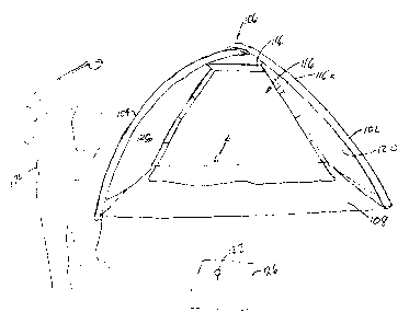
Figure 1, is a front perspective view of one embodiment, a tri-pod embodiment,
the sport ball arresting structure according to the present invention.
Figure 2 is a cross sectional view along line 2-2 in Figure 1.
Figure 2a is a plan view of the sport ball arresting structure of Figure 1.
6
CA 02500606 2005-03-03
Figure 3 is an enlarged perspective view of a portion of Figure 1 illustrating
a
typical connection detail between support structure and ground template.
Figure 4 is an enlarged perspective view of a portion of Figure 1 illustrating
a
typical connection detail between net and support structure.
Figure 5 is an enlarged perspective view of a portion of Figure 2 illustrating
the
flexible pneumatic airway interconnection of the support structure.
Figure 6 is an enlarged perspective view similar to Figure 3 illustrating a
stability ground connection.
Figure 7 is a perspective view of an alternative quadra-pod embodiment of the
present invention showing the pneumatic interconnection of the two inflatable
support tubes
forming the four legs.
Figure 8 is a perspective of the quadra-pod of Figure 7 better illustrating
the
anchoring of the ends of the two inflatable tubes to the four corners of the
base.
Figure 9 is a front view of the quadra-pod of Figure 8 illustrating use of the
quadra-pod for practicing a golf swing.
Detailed Description of Embodiments of the Invention
With reference to the drawing figures, wherein similar characters of reference
denote corresponding parts in each view, in the tri-pod embodiment of Figures
1-6, sport ball
arresting structure 10 has first and second elongate support members 12 and 14
respectively.
Each member is an inflatable resilient, for example rubber, tube or other
inflatable tube which
may be enclosed by a nylon or other flexible but preferably not resilient
fabric sheath 16.
7
CA 02500606 2005-03-03
Sheaths 16 may, in one embodiment not intended to be limiting, have loops 18
integrally
formed on or sewn thereto at intervals along a longitudinal seam to facilitate
a tied connection.
Such tied connection as shown at 20 in Figure 4 facilitate connection between
a supporting
member or leg and backstop netting 26. As shown in Figure 5 such tied
connection as shown
at 22 secures second elongate support member 14 at the medial position on
first member 12.
As may be seen in Figure 3 additional loops 18a are provided on first member
12 for
connection to tie-downs 13 to resist wind forces. Sheath 16 on first support
member 12 may
have a flexible fabric such as tab 30 attached at each end of the sheath. The
second support
member 14 may require only one such tab 30 at only one of its ends.
A fabric template 34 of generally triangular configuration having a base 36
and
sides 38 may be placed upon the ground or other playing surface and the
elongate support
members 12 and 14 respectively fastened thereto by means of fasteners 40 or
the like engaging
tabs 30. Support member 12 is of a length that when its extremities 12a and
12b are fastened
to the ends of base 36 of triangular template 34, it becomes deformed during
inflation into an
arcuate, such as a semi-circular, shape. Support member 14 on the other hand,
is of a shorter
length than member 12 and when inflated becomes a rigid linear support secured
to the medial
point of member 12 and extending downwardly sloping toward the apex of
template 34 and
secured thereto by means of fasteners 40 which pass through fabric tab 30 and
template 34.
Supporting members 12 and 14 are in pneumatic fluid communication with
each other via a small diameter flexible airway such as tube 42. Tube 42 may
be provided
with a pressure relief valve 44. Pressurized air is introduced through one-way
valve 48 located
near one end of support member 12. Flexible tube 42 allows such air to pass
freely into
second support member 14 thereby allowing simultaneous inflation of both
support members.
As support members 12 and 14 become fully inflated, the three sides of
triangular template 34
are tensioned thereby maintaining stability of the structure.
8
CA 02500606 2005-03-03
Additional stability in a direction transverse to first support member 12
after
assembly and inflation may be achieved by inserting an elongate rigid bar 52
through the
looped fabric of tabs 30 sewn into each end of covering sheath 16. Bar 52 may
have an
aperture 54 at each of its ends for pinning by way of rod 58 to the ground.
A further example of the inflatable multi-pod structure 100 according to the
present invention is depicted in Figures 7-9, wherein the four legs of a
quadra-pod
embodiment are formed by two, pneumatically interconnected, inflatable tubes
102 and 104.
Tubes 102 and 104 criss-cross at vertex 106. The ends of tubes 102 and 104 are
mounted, for
example in a manner similar to that illustrated in Figure 3, to the
corresponding four corners of
base 108. Base 108 may be a single flexible square or rectangular sheet, or
may be formed as
a template or an outline of straps for example in the manner illustrated for
the tri-pod
embodiment of Figures 1-6. Tubes 102 and 104 are advantageously pneumatically
interconnected by flexible tube 110. A pressure relief valve 112 may also be
provided, for
example, on the end of one of the tubes. An inflation valve 114 is provided,
for example, on
one end of the other tube.
A backstop net 116, which in a preferred embodiment is of flexible mesh, is
suspended within the enclosure or cavity defined by tubes 102 and 104. In one
embodiment,
the upper edges 116a of net 116 are suspended from the rear pair of legs, that
is, from the
rearward ends of tubes 102 and 104, for example, by suspension means such as
for example
flexible and/or resilient straps 118. Net 116 is suspended either from the
rear pair of legs or
from the flexible material forming the side walls 120 extending between and
mounted to tubes
102 and 104. The intention is to suspend net 116 generally vertically within
the enclosure but
without making net 116 sufficiently taut so as to cause rebound of a ball 122
striking the net.
The use of the pneumatic support structure provides a resiliency to the entire
supporting frame and thus this resiliency is transmitted to net 116 via straps
118. Thus, it is
not merely the billowing of net 116 when struck by ball 122 forcefully
impacting net 116
9
CA 02500606 2012-10-04
when driven in direction A, that accounts for the entire dampening of the
motion of the ball
such as when ball 122 is struck by a golfer 124 from a practice tee 126 placed
directly in front
of the entrance to the quadra-pod structure. Because the pneumatic tubes are
by their nature,
somewhat resilient, not only are rebounds of ball 122 from tubes 102 and 104
of less force
Thus, an inflatable multi-pod ball arresting net supporting structure
according
to the present invention, such as the tri-pod and quadra-pod designs
illustrated, which are not
intended to be limiting, provide for a relatively lightweight, for example in
the order of thirty
pounds, and portable erectable structure which provides a practice enclosure.
For example, in