Note: Descriptions are shown in the official language in which they were submitted.
CA 02500641 2005-03-14
FILLING VALVE APPARATUS
CROSS-REFERENCE TO RELATED APPLICATIONS
[0001] The subject patent application claims priority to and all the benefits
of U.S.
Provisional Patent Applications Serial Nos. 60/552,788 and 60/552,772, both of
which were
filed on March 12, 2004.
BACKGROUND OF THE INVENTION
1. Field of the Invention
[0002] The subject invention relates to filling valve apparatuses for filling
a container with a
fluid, such as filling a bottle with a beverage.
2. Description of Related Art
[0003] Beverage filling machines typically include a large number of filling
valve
apparatuses, such as 40, 60, 72, 100, 120, or 130 filling valve apparatuses on
any one
beverage filling machine. Each of the filling valve apparatuses operate in
sequence to fill a
series of containers with a desired beverage, for example. There are numerous
configurations of filling valve apparatuses and a variety of different methods
for performing
the filling operation. However, one common feature relates to the gases being
vented from
the container during the filling of the container with the fluid. The venting
is typically
accomplished through the use of a movable or stationary vent tube.
[0004] Examples of movable vent tubes are disclosed in U.S. Patent Nos.
4,979,546 and
5,884,677, which may move between a closed position blocking the flow of fluid
into the
container and an open position allowing the flow of fluid into the container.
As the fluid
flows into the container the gases within the container are vented up through
the vent tube
1 Docket No. 65,111-086
CA 02500641 2005-03-14
until the container reaches a predetermined fill level. At this point, the
vent tube is blocked
to prevent any further ventilation of the gases, which in turn will
automatically stop the flow
of fluid. The fluid, however, can have a tendency to leak or drip into the
container. As
known to those skilled in the art, this leaking or dripping creates a host of
problems.
[0005] One solution to reduce or even eliminate the leaking or dripping is to
install a screen
within the flow opening of the filling valve apparatus. Both the '546 and '677
patents
disclose filling valve apparatuses having screens movably mounted to the vent
tube. Surface
tension is created between the screen and the fluid material, which operates
to hold the fluid
material within the holes of the screen. Screens however can have drawbacks.
The screens
are an added expense, can be difficult to install, will clog over time, and
are subject to
servicing.
[0006] Another solution to reduce or eliminate the leaking or dripping is to
form a fluid trap
in the filling valve apparatus. U.S. Patent No. 4,442,873 discloses a filling
valve apparatus
with a fluid trap, which eliminates the need for a screen. These types of
designs, however,
traditionally suffer from slow fill rates. Also, the flow of fluid can become
agitated, which
can cause foaming and a number of other problems.
[0007] Accordingly, it would be desirable to develop a filling valve apparatus
that
eliminates the use of a screen and maintains fast fill rates while retaining a
laminar flow of
the fluid passing into the container. Further, it would be advantageous to
develop a filling
valve apparatus that can be easily and quickly installed and serviced.
SUMMARY OF THE INVENTION AND ADVANTAGES
[0008] The subject invention includes a filling valve apparatus for filling a
container with a
fluid. The apparatus comprises a body portion defining an aperture for
directing the fluid
2 Docket No. 65,111-086
CA 02500641 2005-03-14
into the container with the body portion having an inner wall terminating at
the aperture to
define a sealing seat. The inner wall extends below the seat to define a trap
for the fluid. A
cage extends from the body portion with the cage having an inner wall mating
with the inner
wall of the body portion to define a continuous inner surface. A movable
member has a seal
movably disposed within the body portion between a closed position with the
seal seated
against the sealing seat for blocking a flow of the fluid into the container
and an open
position with the seal spaced from the sealing seat for allowing the fluid to
flow into the
container. The apparatus is characterized by the movable member having an
outer surface
that is complementary in configuration to the continuous inner surface to
define a smooth
passageway for the fluid as the fluid is directed into the container thereby
ensuring a laminar
flow of the fluid between the inner and outer surfaces and into the container.
[0009] The subject invention also includes a filling valve apparatus
comprising a valve
assembly selectively mounted to the body portion and extending outwardly
therefrom. The
valve assembly including the cage and a stem movably mounted to the cage with
the stem
defining an upper vent tube and having a seal seated against the body portion
when the stem
is in a closed position and spaced from the body portion when the stem is in
an open
position. A cap assembly is selectively mounted to the valve assembly. The cap
assembly
includes a cap and a spring with the cap having a seal engaging the stem when
the stem is in
the closed position. A lower vent tube assembly is selectively mounted to the
upper vent
tube of the stem with the lower vent tube assembly including a ball cage and a
check ball
disposed within the ball cage for selectively sealing the upper and lower vent
tubes.
[0010] Accordingly, the subject invention eliminates the use of a screen
through the use of a
trap. The subject invention ensures quick fill rates and laminar flow by
uniquely configuring
the components to provide a smooth uninterrupted passageway. The subject
invention also
Docket No. 65,111-086
CA 02500641 2005-03-14
compartmentalizes the filling valve apparatus into distinct components,
thereby increasing
the efficiency for installation and servicing of the filling valves.
BRIEF DESCRIPTION OF THE DRAWINGS
[0011] Other advantages of the present invention will be readily appreciated
as the same
becomes better understood by reference to the following detailed description
when
considered in connection with the accompanying drawings wherein:
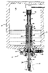
[0012] Figure 1 is a partially cross-sectional view of a filling valve
apparatus connected to a
beverage filling machine in a closed position;
[0013] Figure 2 is a partially cross-sectional view of the filling valve
apparatus in an open
position;
[0014] Figure 3 is a partially cross-sectional view of the filling valve
apparatus in an
intermediate fill position;
[0015] Figure 4 is an exploded perspective view of the filling valve
apparatus;
[0016) Figure 5 is an exploded partially cross-sectional view of the filling
valve apparatus;
[0017] Figure 6 is an enlarged fragmentary cross-sectional view of an
uninterrupted smooth
passageway of the filling valve apparatus; and
[0018] Figure 7 is an enlarged cross-sectional view of a ball cage with a
check ball.
DETAILED DESCRIPTION OF THE INVENTION
[0019) Refernng to the Figures, wherein like numerals indicate like or
corresponding parts
throughout the several views, a filling valve apparatus for filling a
container 12 with a fluid
14 is generally shown at 10 in Figures I-5. The filling valve apparatus 10 is
connected to a
tank 16 of a beverage filling machine. As discussed in the background section
above, there
4 Docket No. 65,111-086
CA 02500641 2005-03-14
are typically 40, 60, 72, 100, 120, or 130 filling valve apparatuses on any
one beverage
filling machine. A typical tank 16 or ring bowl has an annular configuration
and contains
the liquid or beverage material for filling the containers. A space is
disposed above the
liquid for providing a headspace 18 for a pressurized inert gas such as carbon
dioxide or
nitrogen. The tank 16 and other associated components of the beverage filling
machine do
not form part of the claimed invention and will therefore not be discussed in
any detail. It
should be appreciated that the tank 16 and beverage filling machine may be of
any suitable
design or configuration. The example illustrated discloses the filling valve
apparatus 10 for
use with filling bottles with a beverage. It should be appreciated that the
filling valve
apparatus 10 could fill any type of container, such as a can, jar, or bottle,
with any type of
fluid material, such as carbonated beverages, juices, water, or the like. Each
of the filling
valve apparatuses 10 are substantially identical such that only one filling
valve apparatus 10
will be discussed in any greater detail below.
[0020] The filling valve apparatus 10 includes a body portion 20 having a
mounting flange
22, which abuts the beverage filling machine. The body portion 20 also defines
an aperture
24 for directing the fluid 14 into the container 12. The body portion 20 has
an inner wall 26
terminating at the aperture 24 to define a sealing seat 28. The inner wall 26
also extends
below the seat 28 to define a trap for the fluid 14. As best shown in Figure
6, an aperture
wall 30 extends from the sealing seat 28 downward toward the container 12.
Specifically,
the aperture wall 30 curves inwardly toward the aperture 24 from the sealing
seat 28 and
straightens to extend vertically toward the container 12. The aperture wall 30
then curves
inwardly again toward the aperture 24 at an opposing end from the sealing seat
28. A seal
32 is mounted to a top of the body portion 20 for sealing engagement with the
tank 16. Also
a container seal 34 is mounted to a bottom of the body portion 20 about the
aperture 24.
Docket No. 65,111-086
CA 02500641 2005-03-14
Additional devices, such as a snift valve 36 or a purge valve (not shown), may
be mounted
to the body portion 20 to assist in the operation of the filling machine as is
known in the art.
[0021] A cage 38 extends from the body portion 20 and into the tank 16.
Preferably, the
cage 38 is a separate component mounted within a machined groove in the body
portion 20.
The cage 38 includes a lip 40 that is trapped between the body portion 20 and
the tank 16
when the filling valve apparatus 10 is installed on the tank 16 which in turn
secures the cage
38 to the body portion 20 and the tank 16. It should be appreciated that the
cage 38 could be
an integral part of the body portion 20. The cage 38 extends through the fluid
14 in the tank
16 up to the headspace 18. The cage 38 includes a number of openings 42 for
allowing the
fluid 14 to flow into the cage 38 and down into the body portion 20. The cage
38 has an
inner wall 44 mating with the inner wall 26 of the body portion 20 to define a
continuous
inner surface 26, 44.
(0022] A movable member 46, having a seal 48 mounted thereto, is movably
disposed
within the body portion 20. As is discussed in greater detail below, the
movable member 46
moves between a closed position with the seal 32 seated against the sealing
seat 28 for
blocking a flow of the fluid 14 into the container 12 and an open position
with the seal 32
spaced from the sealing seat 28 for allowing the fluid 14 to flow into the
container 12. The
seal 32 also engages a portion of the curved aperture wall 30 when in the
closed position.
The movable member 46 includes a flange 50 with the flange 50 having a distal
end. As
discussed in greater detail below, the distal end remains within the trap
during the movement
of the movable member 46 between the closed and open positions for preventing
gases from
leaking around the trap during an operation of the apparatus. Preferably, the
seal 48 is
mounted to the movable member 46 within the flange 50 by an insert 52.
6 Docket No. 65,111-086
CA 02500641 2005-03-14
[0023] The illustrated embodiment discloses the filling valve apparatus 10
configured to fill
bottles 12 with a liquid beverage 14. In this illustrated embodiment, the
movable member
46 is further defined as a stem 46 movably mounted within the cage 38. The
stem 46
includes a bell-shaped portion 54 and an upper vent tube 56 extending from the
bell-shaped
portion 54. The bell-shaped portion 54 and the upper vent tube 56 have aligned
bores for
ventilating gases during an operation of the apparatus. The flange 50 is
preferably an
integral part of the bell-shaped portion 54.
[0024] The cage 38 includes an intermediate support 58 and the bell-shaped
portion 54
includes a narrower section that slides within the intermediate support 58.
The bell-shaped
portion 54 also includes a notch that selectively engages the intermediate
support 58 to
provide a stop for the stem 46 when the stem 46 is in the open position. The
cage 38 also
includes an exterior recess 60 formed at a top thereof (see Figures 4 and 5).
[0025] The cage 38, stem 46, seal 48, and upper vent tube 56 define a unitary
valve or
cartridge assembly 62 selectively mounted to the body portion 20. The valve
assembly 62
also includes a guide block 64 secured to the upper vent tube 56. Preferably,
the seal 48 and
guide block 64 of the valve assembly 62 are formed of a polymeric material.
The guide
block 64 includes an opening such that the upper vent tube 56 can extend
therethrough. A
fastener 66, such as a clip, secures the guide block 64 to the upper vent tube
56 such that the
guide block 64 and stem 46 move as a single unit. A spring 68 is disposed
within the cage
38 to continuously bias the stem 46 toward the open position. The spring 68
engages the
guide block 64 at one end and the intermediate support 58 at the other end.
Hence, the
spring 68 reacts against the cage 38 on one end and the stem 46 on the other
end. The cage
38, stem 46, seal 48, upper vent tube 56, and guide block 64 are all
interconnected to define
a pre-assembled unitary valve assembly 62.
7 Docket No. 65,111-086
CA 02500641 2005-03-14
[0026] The filling valve apparatus 10 also includes a cap or charging assembly
70
selectively mounted to the valve assembly 62. The cap assembly 70 includes a
cap 72 and a
spring 74 secured to the cap 72. The cap 72 has a seal 76 engaging the stem 46
when the
stem 46 is in the closed position (see Figure 1). The cap assembly 70 further
includes a
sleeve 78 mounted within the cap 72. In addition, the cap assembly 70 includes
a cover 80
mounted to an opposing end of the spring 74. The cover 80 is disposed on the
recess 60 of
the cage 38 and substantially surrounds the block 64. Preferably, the cap 72,
seal 76, and
cover 80 are formed of a polymeric material. The cap 72, seal 76, spring 74,
sleeve 78, and
cover 80 are all interconnected to define a pre-assembled unitary cap assembly
70.
[0027] The filling valve apparatus 10 further includes a lower vent tube
assembly 82
mounted to the stem 46. In the illustrated embodiment, the lower vent tube
assembly 82 is
mounted to the bell-shaped portion 54 of the stem 46. The lower vent tube
assembly 82
includes a bore aligned with the bores of the bell-shaped portion 54 and the
upper vent tube
56 for ventilating the gases within the container 12 during an operation of
the filling valve
apparatus 10. The lower vent tube assembly 82 also includes a deflector 84 for
redirecting
any fluid 14 toward the walls of the container 12. Preferably, the stem 46
includes a locking
device 86 and the lower vent tube assembly 82 includes an integral groove 88
engaging the
locking device 86 when the lower vent tube assembly 82 is mounted to the stem
46. Even
more preferably, the locking device 86 is at least one seal 86 disposed within
the bell-shaped
portion 54 of the stem 46. In the embodiment illustrated, the locking device
86 includes a
pair of seals 86 that are secured to the stem 46 by the insert 52.
[0028] As also shown in Figure 7, the lower vent tube assembly 82 includes a
ball cage 90
having a ball seat 92. A check ball 94 is disposed within the ball cage 90 for
selectively
engaging the ball seat 92 to seal the bores. The ball cage 90 is geometrically
configured to
8 Docket No. 65,111-086
CA 02500641 2005-03-14
prevent undesirable engagement of the check ball 94 with the ball seat 92. In
particular, the
ball cage 90 includes three elongated arms that are lengthened to allow the
check ball 94 to
move upward within the ball cage 90 during certain conditions without engaging
the ball
seat 92.
[0029) The check ball 94 is spherical and defines a radius of curvature. The
ball seat 92 of
the ball cage 90 includes a radius of curvature that is complementary in
configuration with
the radius of curvature of the check ball 94 for preventing gases from leaking
into the bores
during an operation of the apparatus. In particular, the radii of curvature
ensure a proper and
adequate seal between the check ball 94 and the ball cage 90, thereby reducing
or
eliminating the seepage of gases into the bores and the resultant leakage of
fluid 14 into the
container 12. This is an improvement over prior art ball cage/check ball
assemblies that can,
at times, allow seepage of gases.
[0030] As shown in Figures 4 and 5, the body portion 20, valve assembly 62,
cap assembly
70, lower vent tube assembly 82, and snift valve 36 are all pre-assembled
separate and
distinct components of the filling valve apparatus 10. These separate pre-
assembled
components house the working parts of the apparatus 10 into easily assembled
and serviced
pieces. The pre-assembled components utilize an adhesive composition that is
strategically
disposed within the pre-assembled components to permanently bond, or lock,
certain pieces
together. This adhesive also functions to seal all of the various parts of the
pre-assembled
components. Each of the pre-assembled components can be marketed and sold as
disposable
single units. During assembly or servicing of the filling valve apparatus 10,
each of these
components can be quickly and efficiently installed or replaced. This
procedure greatly
increases the efficiency of the service process and ensures that all of the
working parts are
replaced, which in turn equates to reliable and consistent maintenance of the
filling valve
9 Docket No. 65,111-086
CA 02500641 2005-03-14
apparatus 10. This compartmentalizing feature is an improvement over prior art
filling valve
apparatuses.
[0031] Turning to Figures 1-4 and in particular Figures 5 and 6, another
unique feature of
the filling valve apparatus 10 is discussed in greater detail. In particular,
the movable
member 46 has an outer surface 96 that is complementary in configuration to
the continuous
inner surface 26, 44 to define a smooth passageway for the fluid 14 as the
fluid 14 is directed
into the container 12 thereby ensuring a laminar flow of the fluid 14 between
the inner 26,
44 and outer 96 surfaces and into the container 12. The continuous inner
surface 26, 44
includes a first substantially vertical section 98 and an outwardly curved
section 100
extending from the first vertical section 98 of the inner surface 26, 44.
Similarly, the outer
surface 96 includes a first substantially vertical section 102 and an
outwardly curved section
104 extending from the first vertical section 102 of the outer surface 96. The
sections 102,
104 of the outer surface 96 are complementary in configuration with the
sections 98,100 of
the inner surface 26, 44 to further define the smooth passageway having an
uninterrupted
substantially vertical portion and an uninterrupted outwardly curved portion
for directing the
flow of fluid 14 outboard of the vertical sections 98, 102.
[0032] The continuous inner surface 26, 44 further includes a second
substantially vertical
section 106 extending from the curved section 100 of the inner surface 26, 44.
The
continuous inner surface 26, 44 further includes a pocket section 108
extending from the
second vertical section 106 of the inner surface 26, 44 to further define the
trap for the fluid
14. Similarly, the outer surface 96 further includes a second substantially
vertical section
110 extending from the curved section 104 of the outer surface 96. The second
vertical
section 110 of the outer surface 96 is aligned with the second vertical
section 106 of the
inner surface 26, 44 to further define the smooth passageway.
Docket No. 65,111-086
CA 02500641 2005-03-14
[0033] In the preferred embodiment, the inner wall 44 of the cage 38 defines
the first
vertical section 98 and the curved section 100 of the inner surface 26, 44.
The inner wall 26
of the body portion 20 defines the second vertical section 106 of the inner
surface 26, 44.
The bell-shaped portion 54 of the movable member 46 defines the outer surface
96 having
the first vertical section 102 and the curved section 104. The flange 50 of
the bell-shaped
portion 54 further defines the outer surface 96 and the smooth passageway. In
particular, the
flange 50 defines the second substantially vertical section 110 of the outer
surface 96 which
is aligned with the second vertical section 106 of the inner surface 26, 44 to
further define
the smooth passageway.
[0034] The sealing seat 28 is preferably aligned vertically with the first
vertical section 98 of
the inner surface 26, 44 such that the trap is entirely disposed outboard of
the first vertical
section 98 of the inner surface 26, 44. This geometrical orientation operates
to ensure a
smooth laminar flow of the fluid 14. The first vertical section 98 and the
curved section 100
of the inner surface 26, 44 define a first radius. Similarly, the first
vertical section 102 and
the curved section 104 of the outer surface 96 define a second radius. In the
preferred
embodiment, the second radius is equal to the first radius such that this
geometrical
relationship further ensures a smooth laminar flow of the fluid 14.
[0035] Refernng to Figures 1-3, a brief description of the operation of the
subject filling
valve apparatus 10 will be discussed. As will become apparent to those skilled
in the art,
there are a number of additional operations that are not addressed. These
steps are well
known and do not form any part of the novelty of the subject invention.
[0036] As shown in Figure 1, the stem 46 is in the closed position with the
seal 48 of the
stem 46 engaging the sealing seat 28 of the body portion 20 to block the flow
of liquid 14
into the aperture 24 and the bottle 12. Figure 2 illustrates the stem 46 in
the open position
11 Docket No. 65,111-086
CA 02500641 2005-03-14
with the seal 48 spaced from the sealing seat 28. The liquid 14 flows through
the smooth
passageway between the inner surfaces 26, 44 of the cage 38 and body portion
20 and the
outer surfaces 96 of the stem 46. As mentioned above, the inner 26, 44 and
outer 96
surfaces are geometrically configured to provide an uninterrupted smooth path
for the liquid
14. The liquid 14 then moves through the trap in the body portion 20 and
reverses direction
to temporarily flow upward. Once the liquid 14 passes over the sealing seat
28, gravity pulls
the liquid 14 downward through the aperture 24, past the container seal 34 and
into the bottle
12. The liquid 14 flows along the aperture walls 30, container seal 34, and
bottle 12 in a
smooth laminar manner because of the unique geometrical configurations of the
inner 26, 44
and outer 96 surfaces. Gases within the bottle 12 evacuate out of the bottle
12 and up
through the lower vent tube assembly 82 as the bottle 12 is filled with the
liquid 14. As
appreciated by those skilled in the art, as a neck of the bottle 12 becomes
narrower, the flow
of the gases increases. This increased flow of gases can push the check ball
94 upward
within the ball cage 90, see Figure 2. In some prior art systems, the check
ball 94 can even
engage the ball seat 92, which reduces the effectiveness of the filling
operation. As
discussed above, the ball cage 90 is geometrically configured such that the
check ball 94 can
move upward within the ball cage 90 without engaging the ball seat 92.
[0037] Turning to Figure 3, the bottle 12 is now close to a predetermined fill
position. The
check ball 94 engages the ball seat 92, which, as discussed above, have
complementary radii,
to block the bore in the lower vent tube assembly 82. The venting of gases
through the
lower vent tube assembly 82 and stem 46 are now stopped. The liquid 14
remaining in the
aperture 24 falls down into the bottle 12. Figure 3 specifically illustrates
the moment in time
where the check ball 94 has just engaged the ball seat 92 and the remaining
amount of liquid
14 is falling into the bottle 12. The liquid 14 within the trap creates a
liquid seal to prevent
12 Docket No. 65,111-086
CA 02500641 2005-03-14
the evacuation of gases up and around the stem 46. In particular, the distal
end of the flange
50 remains disposed within the liquid 14 caught in the trap to define a liquid
barner. Hence,
any gases attempting to escape will encounter the flange 50 and then the
liquid barrier.
[0038] The stem 46 is then moved downwardly to return to the position shown in
Figure 1
and the filled bottle 12 is removed. The filling process can now repeat.
[0039] The invention has been described in an illustrative manner, and it is
to be understood
that the terminology which has been used is intended to be in the nature of
words of description
rather than of limitation. As is now apparent to those skilled in the art,
many modifications
and variations of the present invention are possible in light of the above
teachings. It is,
therefore, to be understood that within the scope of the appended claims the
invention may be
practiced otherwise than as specifically described.
13 Docket No. 65,111-086