Note: Descriptions are shown in the official language in which they were submitted.
CA 02500642 2005-03-30
WO 2004/031755 PCT/US2003/031718
FOLDED ARRAY CT BAGGAGE SCANNER
SUMMARY OF THE INVENTION
The deficiencies of the prior art are substantially overcome by the CT scanner
of the
present invention which includes a wide angle x-ray tube and multiple sets of
detectors. One
set of detectors is centered on the x-ray source with one or more additional
sets covering outer
edges of the wide angle x-ray beam. The CT scanner of the present invention
has a reduced size
while maintaiung the same tunnel size as conventional scanners. According to
another aspect of
the invention, the sets of detectors have different pitches in order to
maintain a constant inter-
1 o detector angle. Thus, reconstruction algorithms can be simplified.
According to another aspect
of the invention, detectors are positioned on only half of the detector ring.
According to another
aspect of the invention, a second set of detectors sensitive to a different
energy spectrum are
positioned on the other half of the detector ring. The CT scanner of the
present invention can
provide dual energy analysis from a single scan of a bag, using the multiple
sets of detectors.
15 According to another aspect of the invention, the x-ray source operates at
a reduced flux
level from conventional systems. Due to the compact size of the CT scanner of
the invention,
the shorter distances from the source to the detector allows for a less
powerful x-ray. According
to another aspect of the invention, a portion of a bag can be scanned multiple
times with the
results being averaged. The data from the multiple scans is averaged to remove
noise. The
20 resulting reduction in noise allows a reconstruction of heavy bags with a
reduced flux x-ray
source.
CA 02500642 2005-03-30
WO 2004/031755 PCT/US2003/031718
According to another aspect of the invention, the reduced size CT scanner is
incorporated
into an airline check-in desk. The CT scanner is positioned to allow the
passenger to insert the
bag to be checked. Upon successful scanning and analysis (or prior to scanning
and analysis),
the baggage is tagged by airline personnel in the regular manner and
transferred to the existing
baggage handling system. According to another aspect of the invention, a
plurality of CT
scanners are networked
BRIEF DESCRIPTION OF THE DRAWINGS
Fig. 1 is a cross sectional view of a conventional CT scanner.
Fig. 2 is a perspective view of a CT scanner according to an embodiment of the
present
1 o invention.
Figs. 3A and 3B are perspective views of a gantry system according to an
embodiment of
the present invention.
Fig. 4 is a cross sectional illustration of a CT scanner gantry according to
an embodiment
of the present invention.
15 Fig. 5 is a perspective view of a detector array component of a CT scanner
according to
an embodiment of the present invention.
Fig. 6 is a front view of a portion of a detector of a CT scanner according to
an
embodiment of the present invention.
Fig. 7 is a cross sectional view of a detector component of a dual energy CT
scanner
2o according to an embodiment of the present invention.
Fig. 8 is a block diagram of the components of a CT scanner according to an
embodiment
of the present invention.
2
CA 02500642 2005-03-30
WO 2004/031755 PCT/US2003/031718
Fig. 9 is a block diagram of computer components of a CT scanner according to
an
embodiment of the present invention.
Fig. 10 is a perspective view of an airline check-in desk according to an
embodiment of
the present invention.
Fig. 11 is a block diagram of a networked CT scanner system according to an
embodiment of the present invention.
Fig. 12 represents the pitch between detector elements according to an
embodiment of the
invention.
Fig. 13 is a cross sectional view of a CT scanner according to another
embodiment of the
to present invention.
Fig. 14A-C represents data from the CT scanner of Fig. 13.
Fig. 15 is a cross sectional view of a CT scanner according to another
embodiment of the
present invention.
DETAILED DESCRIPTION
A CT scanner of the present invention has a more compact size than
conventional
scamlers through the use of a wide angle x-ray source and a folded detector
array, including sets
of detector arrays at different distances from the x-ray source. Fig. 2
illustrates an embodiment
of a CT scanner 100 according to an embodiment of the present invention. The
CT scanner 100
includes a housing 110 with a substantially circular tunnel 120, there
through. The tunnel 120
2o has an input end 121 and an output end 122. A conveyor 123 extends from the
input end 121 to
the output end 122 of the tunnel 120. For ease loading baggage, the conveyor
may extend
beyond the ends of the tunnel 120. Additionally, other conveyors may be
positioned and used to
3
CA 02500642 2005-03-30
WO 2004/031755 PCT/US2003/031718
transfer baggage to or from the conveyor 123 in the CT scanner 100. Coverings
(not shown),
such as lead lined rubber or fabric, may be placed within the tunnel 120 or at
the input end 121
and output end 122, to provide x-ray shielding. The CT scanner 100 has a x-ray
area 130
towards its center. As illustrated in Fig. 2, the x-ray area 130 may be larger
than the ends 121,
122 of the tunnel 130. Alternatively, the housing 110 could be formed of a
single size to
accommodate the size of the x-ray area 130.
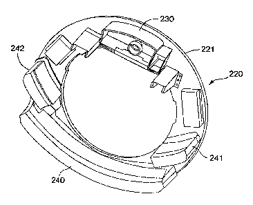
Figs. 3A and 3B illustrate a gantry system disposed within the x-ray area 130
of the
housing 110. The gantry system includes a support structure 210 (Fig. 3A) and
a gantry 220
(Fig. 3B). The support structure 210 includes a base 211 and a circular shaped
vertical support
212. The vertical support 212 is attached to the base 211. The gantry 220
includes a ring 221
which is rotatably attached to the vertical support 212 so that the tunnel 120
passes through the
center of the ring 221. An x-ray source 230 is attached to the ring 221 to
provide a wide angle x-
ray beam over the entire area of the tunnel 120. Preferably, the x-ray source
has a rounded shape
on an upper surface, similar in shape to the outer surface of the gantry. In
this manner, the size
of the gantry can be reduced since it does not need to accommodate the
extensions of a
rectangular x-ray source. Furthermore, the gantry has a three sets of detector
arrays240, 241,
242, positioned on the ring 221 within the projected beam of the x-ray source
230. Notably
absent from the gantry is a computer. Conventional CT scanners include a
computer on the
gantry to process data from the detectors and format the data for transmission
from the gantry to
2o a host computer which operates the scanner. According to an embodiment of
the present
invention, the CT scanner does not include a computer on the gantry. Instead,
data from the
detectors are streamed directly to the host computer. Elimination of the
computer on the gantry
CA 02500642 2005-03-30
WO 2004/031755 PCT/US2003/031718
permits a smaller and lighter gantry. As with conventional CT scanners, the
gantry includes an
edge contact (not shown) for transferring power and control signals to the
gantry and data from
the gantry while the gantry is rotating. Of course, the present invention may
include a computer
on the gantry to perform some of the processing of data as in conventional CT
scanners.
Fig. 4 illustrates the positioning of the x-ray source 230 and the folded
array detectors
240, 241, 242 on the ring 221. The ring 221 of the gantry 220 is substantially
smaller than for
conventional CT scanners with a similar size tunnel 120. According to an
embodiment of the
present invention, the gantry has a diameter of approximately 130 cm, when the
tunnel is
approximately 80 cm in diameter. A conventional CT scanner with a 80 cm
diameter tunnel
to would be approximately 210 centimeters. Thus, with the present invention,
the CT scanner is
reduced in size by approximately 40%. The wide angle x-ray source 230 is
located on the gantry
220 so that the x-ray beam intersects the entire area of the tunnel 120. Since
the x-ray source
230 has a wider beam 250 than for a conventional CT scanner, it can be
positioned closer to the
tunnel. The CT scanner of the present invention includes a folded detector
array including two
15 or more sets of detectors 240, 241, 242 at different distances from the x-
ray source 230. One set
of detectors 240 covers a central portion of the gantry ring and is centered
on the x-ray source at
a distance equal to the source to center detector distance. The other sets of
detectors 241, 242 are
positioned to intersect the outer ranges of the x-ray fan beam 250. According
to an embodiment
of the invention, the second sets of detectors 241, 242 start at the point in
the beam 250 where
2o the inner detectors 240 reach the edge of the ring 221. Alternatively, the
second set of detectors
may start at any location in the beam 250 where the inner detectors end,
depending upon the size
CA 02500642 2005-03-30
WO 2004/031755 PCT/US2003/031718
of the machine and the gantry. The second set of detectors 241, 242 are a
closer distance to the
x-ray source 230 than the inner detectors 240.
Since the detectors are closer to the x-ray source, they can have a shorter
pitch than for
conventional CT scanners without sacrificing flux levels or photon counts.
According to an
embodiment of the present invention, the detector elements are sized and
positioned so that each
set of detectors has substantially identical pitch and flux levels. The closer
distance between the
x-ray source 230 and the second sets of detectors 241, 242 allows a smaller
detector pitch than
for the first set of detectors 240. Since the distance is shorter, the photon
count per unit area at
the second sets of detectors 241, 242 is higher than for the first set of
detectors 240. The higher
1o photon count allows a reduced detector pitch without sacrificing the signal
to noise ratio.
Additionally, with the reduced pitch, a constant inter-detector angle can be
maintained
throughout the fan beam 250. Fig. 12 illustrates the relationship between the
first set of detectors
240 and the second sets of detectors 241, 242. The angles between detectors
(a) remains
constant while the pitch between detectors (81, 82) changes. To maintain the
same angle, the
equation 81/Rl=s2/R2 must be satisfied. Additionally, to maintain a minimum
flux level, the
following equation, (~2xw2)/R22 >_(8lxwl)/R12, where wl and w2 are the widths
of the
detectors, must be satisfied. Since the distance is reduced, both equations
can be satisfied, with
consistent angles and minimal noise interference. These features allow for
simplified
reconstruction software. Known 'equi-angular' fan beam reconstruction
algorithms can be used
2o with minimal modification. According to an embodiment of the invention, the
detector elements
of the first set of detectors 240 are approximately 10 mm long and 2.2 mm
wide. The detector
elements of the second sets of detectors 241, 242 are 8 mm long and 1.8 mm
wide.
CA 02500642 2005-03-30
WO 2004/031755 PCT/US2003/031718
Figs. 5 and 6 illustrate detector assemblies for simplifying the assembly of
the CT
scanner of the present invention and to improve quality control. Fig. 5
illustrates a detector
assembly 300 having a housing 310, a processing board 320 and a detector array
330. The
detector array 330 includes a plurality of detectors (not shown) arranged
along the width of the
assembly 300. As illustrated in Fig. 6, detector assemblies 300, 301, 302 are
attached to the ring
221 of the gantry 220. The detector assemblies 300, 301, 302 are positioned so
that the detector
or each end of the detector array 330 is adjacent to a detector on the end of
an adjacent detector
array. Ideally, for purposes of reconstruction, every detector in the array
would be perpendicular
to and equidistant from the x-ray source. However, with flat detector
assemblies 300 there are
1o slight variations in incidence angle and distance across the assembly.
According to an
embodiment of the invention, a detector assembly at the center of the first
set of detectors 240 is
arranged with a center detector element being perpendicular to the position of
the x-ray source.
For the remaining detector assemblies, the outermost detector element is
perpendicular to the x-
ray source. As illustrated in Fig. 6, the x-ray source direction 350, 351 is
perpendicular to the
left hand side of an assembly on the left hand side of the gantry. The right
hand side of
assemblies on the other side of the gantry would be positioned perpendicular
to the direction of
the x-ray source. Such positioning allows the detector arrays to be properly
angled and nested,
as illustrated in Fig. 6 to minimize the distance between adjacent elements on
different
assemblies.
2o The CT scanner of the present invention is smaller and less costly than
conventional
scanners. The wide beam width provides additional benefits in addition to
reduced diameter.
The shorter source to detector distances, allow for less powerful x-ray
sources which translates to
7
CA 02500642 2005-03-30
WO 2004/031755 PCT/US2003/031718
lower part costs, simplified cooling (quieter) and power requirements. The
decrease in x-ray flux
also requires less shielding, again translating to a cheaper (and lighter)
system.
According to an embodiment of the present invention, the CT scanner operates
in a dual
energy mode. Fig. 7 is a cross sectional view of a detector element 330 for
dual energy
operation. The detector element includes a low energy scintillator layer 331,
a low energy
photodiode layer 332, a copper layer 333, a high energy scintillator layer
334, and a high energy
photodiode layer 335. The high energy layers 334, 335 are wider than the low
energy layers 331,
332. According to an embodiment of the invention, the low energry layers are
approximately 5
mm long and the high energy layers are approximately 10 mm long. The different
lengths create
1 o similar flux levels between the low and high energy layers, even with the
greater shielding from
the copper and additional layers, thereby simplifying data acquisition
electronics and subsequent
signal processing. Alternatively, a dual energy scan can be performed using
known techniques
with a pulsing x-ray source and a single photodiode layer in the detectors.
Fig. 8 illustrates the components of a CT scanner 100 according to an
embodiment of the
present invention. The CT scanner 100 includes the gantry 221, and two
computers 400, 500. A
host computer 400 controls operation of the scanner and retrieves data from
the detectors. A
detection algorithm computer 500 operates on the data to determine whether an
explosive device
or other object of interest is present. Of course, a single computer could be
used to perform all
of the functions for the CT scanner. However, the use of two computers
prevents the extensive
2o processing of the detection algorithm from slowing down the operation and
data collection of the
CT scanner. Also, control and data elements are connected between the gantry
221 and the
computers 400, 500. An AC power input 224, connected to ordinary 240 V AC
power, provides
CA 02500642 2005-03-30
WO 2004/031755 PCT/US2003/031718
the power for the CT scanner. A DC power supply 225 receives the AC power and
converts it to
DC power for powering the processing elements on the gantry. A set of motor
drives 222,
powered by the AC power, or alternatively by the DC power, operate the
conveyor and rotate the
gantry. A data link 223 connects the detector assemblies to the host computer
400. DC power
and the data link are positioned on the ring of the gantry to provide data
during rotation. The
circuit boards 320 on the detector assemblies 300 sample the detectors 1440
times per second.
The data is then transferred, through the data link 223 to the host computer
400. Encoders are
also used to determine the rotational position of the gantry and of the
conveyor. This data is also
provided to the host computer.
1 o The components of the computers are illustrated in Fig. 9. The host
computer 400
includes a motherboard 410 and a data acquisition card 420. The data
acquisition card 420
includes inputs from the imaging array 423, the conveyor belt encoder 422, and
the gantry
encoder. 421. It also includes a field programmable gate array card 424 for
retrieving the data
and forwarding it to the motherboard 410. The motherboard 410 includes a
processor 411, such
as a Pentium processor from Intel, a large RAM 412, and a back-projection
accelerator card 520
for processing the data. It also includes a Host/PCI bridge for sending and
receiving information
from the data acquisition card and other computers. The data retrieved from
the CT scanner is
transferred to the detection algorithm computer 500. An ethernet connection
allows quick
transfer of the large amounts of data. The detection algorithm computer also
includes a
2o motherboard S 10 for proper processing of the data to determine the
existence of explosives or
other materials.
CA 02500642 2005-03-30
WO 2004/031755 PCT/US2003/031718
The data from the CT scanner having a folded detector array can be processed
using
conventional CT operating and reconstruction techniques, such as helical
scanning or start/stop
scanning. The host computer is programmed to control the x-ray source,
conveyor belt, and
reading of detectors according to the desired scanning scheme. The detection
algorithm
computer, similarly, is programmed to reconstruct the CT data based upon the
scanning scheme
which is utilized.
The smaller size of the CT scanner of the present invention allows it to be
more easily
incorporated into the baggage handling process than existing EI~S systems.
Fig. 10 illustrates an
airline check-in desk 700 incorporating a baggage scanner according to an
embodiment of the
1o present invention. As in some conventional check-in desks, the desk 700 of
the present
invention includes two check-in stations 710, 720 with a checked baggage
loading area 730
between them. Multiple desks 700 could be positioned together in the airport
lobby. The CT
scanner 100 of the present invention is positioned at the baggage loading area
730. A passenger,
upon checking in, places his or her baggage on the conveyor at the baggage
loading area 730 or
15 as a standalone system. The baggage is automatically scanned and processed
for the existence of
explosives. If the baggage passes, the check-in personnel can tag it in the
ordinary manner and
forward it to the baggage handling system. With the check-in desk of this
embodiment of the
present invention, very little additional lobby space is needed for scanning
baggage, and no
modifications to the baggage handling system are required. As an option, the
bag can be
2o processed as usual, with the bag tag placed by the ticket agent prior to
scanning. Once checked-
in, the bag is scanned and injected into the baggage handling system. If
desired for improved
operational flow, any suspect bag can be resolved in the baggage makeup area
away from the
10'
CA 02500642 2005-03-30
WO 2004/031755 PCT/US2003/031718
passengers in the terminal area. Alternatively, the CT scanner of the present
invention may be
incorporated into a self service check-in desk, either as part of a check-in
area of the lobby or as
a free standing kiosk.
As described above, the CT scanner of the present invention may be a free
standing,
standalone unit with a TSA operator available for reviewing images and
addreesing potential
threats. According to another embodiment of the present invention, the host
computers of a
plurality of CT scanners 700 are networked together to form a single EI?S. The
networked CT
scanners may include any combination of free standing units, self check-in
units and integrated
check-in desk units. Most bags can be automatically cleared by analysis of the
scan data.
1o However, some may require further review by an operator. Rather than have
an operator at each
scanner, as is used with carry-on baggage, a threat control room 760 with a
plurality of operators
is comiected to the network. If a bag cannot be cleared automatically, the
projection and/or
reconstruction data is transferred to an operator in the threat control room
760. The operator can
then determine whether a threat exists or can be cleared. If the possible
threat is cleared by the
operator, the bag is passed to the baggage handling system in the ordinary
manner. However, if
the threat cannot be cleared, the bag would be passed to other operators for a
manual hand
search. The network may include additional equipment, such as network server
computers 750,
printers 771, network control stations 772, and remote resolution computers
773.
The small size of the baggage scanning system also allows it to be placed in
other
locations for distributed handling of checked baggage. For example, a scanner
could be placed
for curb-side check-in or at rental car return areas for simplified
processing. Additionally, hotels
or other locations could provide check-in baggage service by providing a
scanner and a secure
11
CA 02500642 2005-03-30
WO 2004/031755 PCT/US2003/031718
area for scanned baggage. Guests could have their luggage automatically
processed by the hotel
and securely transferred to the airport without the need for further
processing or delay during
check-in. Additionally, the size of the scanner could permit it to be placed
in a vehicle used to
pick up baggage from various locations for transport to the airport. Free
standing units can be
provided at various locations in the airport for either self checkin or
assisted check-in of
passengers. Alternatively, a CT scanner of the present invention may be used
at security
checkpoints for scanning of carry-on baggage. Each scanner, independent of its
location in the
airport or away from the airport, may be operated as a stand alone unit or may
be networked for
common review by TSA operators.
Fig. 13 illustrates another embodiment of the present invention which provides
additional
reductions in the size and cost. In the third embodiment, the CT scanner 810
has multiple
detectors 841, 842, 843, 844, 845 located on half of the detector ring 811. As
in the first two
embodiments, the detectors are at different distances from the x-ray source
330 and at different
angles. Using half a detector ring is sufficient for creating a CT
reconstruction with a full 360
degrees of data. The half of a detector ring is mathematically equivalent to
collecting data for
180 degrees plus fan beam, which is required for reconstruction. Figs. 14A-14C
illustrate CT
reconstruction. Fig. 14A illustrates reconstruction using a full detector
ring. Fig. 14B illustrates
reconstruction of the same data from half a detector ring. The data from Fig.
14B can be used to
complete a full reconstruction as illustrated in Fig. 14C. Using only half a
detector ring, as in
2o this embodiment, allows the imaging cost to be substantially reduced
because fewer detectors are
required.
12
CA 02500642 2005-03-30
WO 2004/031755 PCT/US2003/031718
In order to cut the cost further, the present invention may operate with
reduced flux levels
from conventional CT scanners. In the design of x-ray systems for baggage, one
often designs
the flux to be enough to penetrate the heaviest 5% of the bags. The majority
ofthe bags require
significantly less flux. By designing the system to provide flux for only the
90~' percentile bags,
the amount of flux is significantly reduced. The reduced flux allows reduction
in the noise levels
and required shielding, which substantially reduces size and cost of the
device. In order to
handle the heavier bags, two or more scans are performed on the bags and the
sinograms are
averaged. The raw data can be analyzed, as discussed below, to determine which
bags or regions
of a bag are likely to require the extra flux. The bag slice gets scanned
twice or more, averaging
the second set of raw data with that obtained in the first rotation, which
will reduce the noise in
the reconstructed image and mimics a higher flux system. One can do this a 3rd
or 4th time for
those 1 thousandth bag slices of very heavily cluttered bags. The present
invention reduces the
need for manual bag searches by providing a practical solution to the
"exceptional" or "shield"
bag problem. Heavy or "shield" objects in unusual bags are scanned several
times to obtain
is useful data with respect to heavily cluttered areas, without the need for a
manual search.
According to another embodiment of the present invention, the CT scanner of
the present
invention can be used for dual energy CT scans with a single pass of the
baggage through the
scanner. Fig. 15 illustrates a CT scanner 910 according to this embodiment of
the invention.
The CT scanner 910 includes a wide-angle x-ray source 930 and two sets of
detectors 940, 950.
2o Each of the sets of detectors 940, 950 includes a plurality of detector
elements 941, 94~, 943,
944, 945, 951, 952, 953, 954, 955. The detector elements for each set are each
positioned on one
half of the detector ring 911, as in the third embodiment. The two sets of
detectors 940, 950 are
13
CA 02500642 2005-03-30
WO 2004/031755 PCT/US2003/031718
sensitive to different energy spectrums. Using the CT scanner of this
embodiment, two CT
slices, of different energies, can be obtained from a single rotation of the
detector ring. This will
allow for a dual energy analysis of the CT images. One can also obtain dual
energy CT images
with back-to-back detectors. The dual energy CT is very useful to reduce the
false alarm of the
machine. This is very desirable in an airport environment. Although Fig. 15
illustrates five
detector arrays for each set of detectors, any number of detector arrays may
be used. Each set of
detectors 940, 950, corresopnding to an energy level of the x-ray source, is
positioned on one
half of the detector ring 911.
The present invention has been described with respect to inspection of checked
baggage,
1 o since it has substantial uses in that field. However, the reduced size of
the folded array CT
scanner according to the present invention can be used in many other
applications for which CT
scanners are used. For example, it may be used for cargo or pallette
inspection or screening. A
larger tunnel is typically necessary for cargo and pallette inspection, and
conventional CT
scanners are correspondingly much larger. The CT scanner of the present
invention has a
significantly smaller size, even with a large tunnel. The present invention
may also be used in
medical CT scanning applications.
Furthermore, the present invention has been described as including an x-ray
source.
Conventionally, CT scanners have used x-ray sources for radiation and
appropriate detectors for
x-rays. Of course, other radiation sources, such as gamma radiation, could
also be used in
2o connection with the present invention. With a different radiation source,
the detectors and/or
scintillator material would need to be changed as appropriate to measure the
proper radiation
spectrum.
14
CA 02500642 2005-03-30
WO 2004/031755 PCT/US2003/031718
Having described at least one embodiment of the invention, modifications,
adaptations
and improvements will be readily apparent to those of ordinary skill in the
art. Such
modification, changes and adaptations are considered part of the invention.