Language selection

Search

Patent 2500695 Summary

Third-party information liability

Some of the information on this Web page has been provided by external sources. The Government of Canada is not responsible for the accuracy, reliability or currency of the information supplied by external sources. Users wishing to rely upon this information should consult directly with the source of the information. Content provided by external sources is not subject to official languages, privacy and accessibility requirements.

Claims and Abstract availability

Any discrepancies in the text and image of the Claims and Abstract are due to differing posting times. Text of the Claims and Abstract are posted:

  • At the time the application is open to public inspection;
  • At the time of issue of the patent (grant).
(12) Patent Application: (11) CA 2500695
(54) English Title: DOUBLE REAR TRACTION ASSEMBLY
(54) French Title: DOUBLE TRAIN DE TRACTION ARRIERE
Status: Deemed Abandoned and Beyond the Period of Reinstatement - Pending Response to Notice of Disregarded Communication
Bibliographic Data
Abstracts

English Abstract


There is provided an integrated rear traction assembly for a vehicle,
comprising
two sprockets and their own hub, accommodating a ratio between a standard
front traction assembly and this rear traction assembly, for a maximized power
of the vehicle, by allowing a control of a slip between the standard front
traction
assembly and the present rear traction assembly.


Claims

Note: Claims are shown in the official language in which they were submitted.
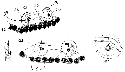

WHAT IS CLAIMED IS:
1. An integrated rear traction assembly as described herein.

Description

Note: Descriptions are shown in the official language in which they were submitted.


CA 02500695 2005-03-15
1
TITLE OF THE INVENTION
Double rear traction assembly
FIELD OF THE INVENTION
[0001] The present invention relates to a double rear traction
assembly.
BACKGROUND OF THE INVENTION
[0002] Current double rear traction assemblies are typically
assembled on top of the rear wheels of the vehicle, and usually decrease the
driving power efficiency of the vehicle. Moreover, double rear traction
assemblies are not currently available for six wheels vehicles.
[0003] There is a need in the art for a double rear traction assembly.
SUMMARY OF THE INVENTION
[0004] There is provided a double rear traction assembly.
[0005] Other objects, advantages and features of the present
invention will become more apparent upon reading of the following non-
restrictive description of embodiments thereof, given by way of example only
with reference to the accompanying drawings.
BRIEF DESCRIPTION OF THE DRAWINGS
[0006] In the appended drawings:

CA 02500695 2005-03-15
2
[0007] Figure 1 shows side perspective views of an assembly
according to an embodiment of the present invention;
[0008] Figure 2 shows side perspective views of a frame of the
assembly of Figure 1;
[0009] Figures 3, 4, 5, 6, 7 illustrates respectively 30 a lower
member of the frame of Figure 2; 4) an upper member of the frame of Figure 2;
5); a middle member of the frame of Figure 2; 6) a first part of a frame plate
of
the frame of Figure 2; and 7) a second part of the frame plate of the frame of
Figure 2;
(0010] Figure 8 is a detail showing a hub and a hub support of a rear
sprocket of the assembly of Figure 1;
[0011] Figure 9 shows views of the hub of Figure 8;
[0012] Figure 10 shows views of the hub support of Figure 8;
[0013] Figure 11 is a view of a stiffener member provided between
two parts of a frame plate of the frame of Figure 2;
[0014] Figure 12 shows views of an axles for a wheel of the
assembly of Figure 1;
[0015] Figure 13 shows views of a tensioning means for tensioning a
belt of the assembly of Figure 1;

CA 02500695 2005-03-15
3
[0016] Figure 14 shows views of a tensioning tube of the tensioning
means of Figure 13;
j0017] Figure 15 shows views of an adjustment rod of the tensioning
means of Figure 13; and
[0018] Figure 16 shows views of a short member sued with the
tensioning means of Figure 13.
DESCRIPTION OF EMBODIMENTS OF THE INVENTION
[0019] Turning to Figure 1 of the appended drawings, there is shown
a rear traction assembly, comprising a frame 10, supporting a rear sprocket 12
and a front sprocket 14 and wheels 16, and a belt 15 tensioned around the
sprockets and wheels.
[0020] As best seen in Figure 2, the frame 10 includes a lower
member 22 (Figure 3), an upper member 24 (Figure 4), a middle member 26
(Figure 5), and a frame plate (Figures 6-7).
[0021] Axles 50 for the wheels (not shown in Figures 2 and 3) are
centered on the lower member 22 (Figure 1 ), and detailed in Figure 12.
[0022] Tension of the belt 15 may be adjusted by means of a short
member 30 of the lower member 22, shown in Figure 16 and a tensioning
means 38 (Figure 13) including a tensioning tube 40 (Figure 14) and an
adjustment rod 42 (Figure 15).

CA 02500695 2005-03-15
4
(0023] The frame plate (Figures 6-7) comprises two parts 28, 28'
assembled on each side of the upper arm of the upper member 24, from the
rear sprocket 12 to the rear sprocket 14. A stiffener member 32 may be
provided between the two parts 28, 28' for strengthening the assembly (Figure
11 ).
[0024] The rear sprocket 12 is mounted on the frame plate by anti-
friction bearings 18. Figure 8 shows details of the anti-friction bearings 18,
comprising a hub 34 (Figure 9) and a hub support 36 (Figure 10) mounted in a
slot 37 provided in the frame plate, so that the position of the rear sprocket
12
is adjustable along an available length of the slot.
(0025] As shown in Figure 1, the lower member 22 and the upper
member 24 are assembled together by welding for example into a generally
trapezoidal shape, reinforced by the middle member 26, and supporting the
frame plate, a distance between the front sprocket 14 and the rear sprocket 12
being adjustable by adjustment of the position of the rear sprocket 12 in the
slot
37of the frame plate discussed hereinabove.
[0026] Therefore, there is provided a rear traction assembly for a
vehicle, comprising two sprockets and their own hub, which allows
accommodating a ratio between a standard front traction assembly and this
rear traction assembly, for a maximized power of the vehicle, by allowing a
control of a slip between the standard front traction assembly and the present
rear traction assembly.
[0027] This double rear traction assembly is an integrated rear
traction assembly and is adaptable to a range of vehicles, including ATV for
example.

CA 02500695 2005-03-15
[0028] It is found that the rear traction assembly according to the
present invention allows an increased traction sweep and an efficient approach
angle for vehicle operating on grounds such as snow and mud, and therefore
allows the vehicles an improved traction on such grounds.
[0029] Although the present invention has been described
hereinabove by way of embodiments thereof, it may be modified, without
departing from the nature and teachings of the subject invention as defined in
the appended claims.

Representative Drawing
A single figure which represents the drawing illustrating the invention.
Administrative Status

2024-08-01:As part of the Next Generation Patents (NGP) transition, the Canadian Patents Database (CPD) now contains a more detailed Event History, which replicates the Event Log of our new back-office solution.

Please note that "Inactive:" events refers to events no longer in use in our new back-office solution.

For a clearer understanding of the status of the application/patent presented on this page, the site Disclaimer , as well as the definitions for Patent , Event History , Maintenance Fee  and Payment History  should be consulted.

Event History

Description Date
Application Not Reinstated by Deadline 2007-06-18
Inactive: Dead - No reply to Office letter 2007-06-18
Deemed Abandoned - Failure to Respond to Maintenance Fee Notice 2007-03-15
Application Published (Open to Public Inspection) 2006-09-15
Inactive: Cover page published 2006-09-14
Inactive: Abandoned - No reply to Office letter 2006-06-16
Inactive: First IPC assigned 2005-05-12
Inactive: IPC assigned 2005-05-12
Inactive: Courtesy letter - Evidence 2005-04-26
Filing Requirements Determined Compliant 2005-04-22
Inactive: Filing certificate - No RFE (English) 2005-04-22
Application Received - Regular National 2005-04-20

Abandonment History

Abandonment Date Reason Reinstatement Date
2007-03-15

Fee History

Fee Type Anniversary Year Due Date Paid Date
Application fee - small 2005-03-15
Owners on Record

Note: Records showing the ownership history in alphabetical order.

Current Owners on Record
TATOU INC.
Past Owners on Record
DENIS BOISVERT
Past Owners that do not appear in the "Owners on Record" listing will appear in other documentation within the application.
Documents

To view selected files, please enter reCAPTCHA code :


To view images, click a link in the Document Description column. To download the documents, select one or more checkboxes in the first column and then click the "Download Selected in PDF format (Zip Archive)" or the "Download Selected as Single PDF" button.

List of published and non-published patent-specific documents on the CPD .

If you have any difficulty accessing content, you can call the Client Service Centre at 1-866-997-1936 or send them an e-mail at CIPO Client Service Centre.


Document
Description 
Date
(yyyy-mm-dd) 
Number of pages   Size of Image (KB) 
Description 2005-03-15 5 134
Abstract 2005-03-15 1 11
Claims 2005-03-15 1 3
Drawings 2005-03-15 6 113
Representative drawing 2006-08-21 1 21
Cover Page 2006-08-29 1 43
Filing Certificate (English) 2005-04-22 1 157
Request for evidence or missing transfer 2006-03-16 1 100
Courtesy - Abandonment Letter (Office letter) 2006-07-31 1 166
Reminder of maintenance fee due 2006-11-16 1 112
Courtesy - Abandonment Letter (Maintenance Fee) 2007-05-10 1 174
Correspondence 2005-04-22 1 26
Correspondence 2007-03-14 1 27
Correspondence 2007-07-05 1 13