Note: Descriptions are shown in the official language in which they were submitted.
CA 02501162 2005-04-04
WO 2004/034732 PCT/US2003/027496
-1-
ACOUSTIC REPRODUCTION DEVICE WITH IMPROVED
DIRECTIONAL CHARACTERISTICS
TECHNICAL FIELD
The present invention relates to acoustic reproduction devices and
more particularly to sound radiator systems comprising means for radiating
acoustic energy to a given listening position or listening area within a
listening
room, such that undesired reflections experienced at the listening position
and
within the said listening area originating from for instance room boundaries
or
from specific surfaces of obstacles in the room can be either avoided
altogether
or at least attenuated in a controlled manner.
BACKGROUND OF THE INVENTION
In designing loudspeakers and systems of loudspeakers both for
domestic and professional use, one important acoustical characteristic of such
systems is the directivity of radiation of acoustic energy to the
surroundings.
Generally sound is not only radiated directly towards the listening position
in
the listening room but also towards the various boundaries of the room and
towards different objects present in the room. When sound impinges on such
boundaries at least a part of the acoustic energy is reflected from the
boundary
and some of these reflections eventually reach the listening position or
listening
area together with the sound energy received directly from the loudspeaker.
Whereas some of this reflected acoustic energy contributes in a positive sense
to the overall sound perception at the listening position, other reflections
have
been found to be generally problematic, leading for instance to undesired
comb-filter effects that affect the timbre of the sound negatively. It has
specifically been found that reflections from the portions of the floor and
ceiling
between the loudspeaker and the listening position are generally undesirable,
and that they should at least be suitably attenuated as compared to the direct
sound from the loudspeaker. Also reflections from a wall or other spacially
extended obstacle behind the loudspeaker will often lead to the above
mentioned undesirable comb-filter effects.
CA 02501162 2011-06-09
WO 2004/034732 PCT/US2003/027-t96
-2-
It has furthermore been recognized that there should be a balance
between the sound received at the listening position directly from the
loudspeaker and the reverberant sound, i.e. the sound caused by reflections.
In
a typical loudspeaker set-up in a listening room the level of the direct sound
and of the reverberant sound are on the same order of magnitude. If the above
mentioned undesirable effects of some of the reflections in the room were not
taken into consideration, a uniform radiation from the loudspeaker in all
directions should thus be aimed at. It is however apparent from the above that
a suitable compromise between this omnidirectional radiation of sound energy
and attenuation of radiation in some directions must be considered, for
instance by tailoring the directivity of the loudspeaker - or of the different
loudspeaker units (treble unit, mid-frequency unit, etc.) in loudspeaker
systems
comprising more than one radiating unit.
Means of tailoring the directivity of loudspeakers are numerous within
the art of electroacoustics and have been described regularly at least since
the
1930's. Such means have generally comprised various forms of acrostic lenses
or either plane or curved reflector surfaces placed in front of a loudspeaker
driver diaphragm. See, for example, U.S. Patent No. 5,615,176, U.S. Patent
No. 6,068,080 and U.S. Patent No. 6,435,301, each to the present inventor.
See, also, U.S. Patent No. 4,836,329 to Klayman and UK Patent No. 830,745
to Quennell.
SUMMARY OF THE INVENTION
Based on the above background it is an advantage of the present
invention to provide a sound reproduction system which does not suffer from
the above mentioned drawbacks relating to unwanted reflections and the
resulting comb-filter effects but which on the other hand still maintains a
broad
and uniform directional characteristic throughout the region in the listening
room in which listening positions are located.
Specifically the device according to embodiments of the invention
should provide attenuation of typical reflections from the floor and ceiling
CA 02501162 2005-04-04
WO 2004/034732 PCT/US2003/027496
-3-
between the device and the listening position and of the reflections from
boundaries or obstacles behind the device.
The acoustic requirements of such a device can be broadly
reformulated by requiring that the device must minimize the reflected sound
from those surfaces (i.e. room boundaries or surfaces of obstacles in the
room,
the dimensions of which are large enough compared with the wavelength of the
radiated sound to cause appreciable reflections) that result in essentially
the
same interaural difference of the reflected sound from that particular surface
and of the sound received directly from the device. Those reflections that
fulfill
the above requirement are the reflections which are most likely to give rise
to
the above mentioned undesired comb-filter effects.
The above requirement is illustrated in Figures 1a and 1b. Thus Figure
1a shows a horizontal cross-section through a listening room, a sound source
(for instance the device according to the invention) and a listener placed in
front of the sound source. The sound received directly from the source at the
two ears of the listener is indicated by the arrows D whereas sound reflected
from the left wall of the room is indicated by R. The interaurel difference
(both
time- and intensity differences as a function of frequency) of the direct
sound D
is close to zero at all frequencies whereas the interaural difference of the
reflected sound R is substantially different from zero. The corresponding
interaural time difference will be different from zero at all frequencies
whereas
the interaural intensity difference will tend to increase with frequency.
Reflections of this kind are not attenuated by the device according to the
invention as defined by the above requirement.
Referring now to Figure 1 B, there is shown a vertical cross-section
through the listening room and the sound source and listener are shown
together with the direct sound D. The reflections from the floor, Rf, from the
ceiling, R, and from the wall behind the sound source, Rb, are also shown. The
interaural differences of each of the above three reflections will be
approximately equal to the interaural difference of the direct sound, i.e. in
this
specific case approximately equal to zero.
CA 02501162 2005-04-04
WO 2004/034732 PCT/US2003/027496
-4-
According to embodiments of the invention, the above requirements
based on the interaurel differences are fulfilled by providing a sound
reproduction device having a substantially uniform directivity in the
horizontal
plane through the device in front of the device from approximately - 90
degrees
azimuth angle to + 90 degrees azimuth angle, a substantial attenuation of the
directivity in the horizontal plane through the device at the back of the
device
from approximately + 90 degrees azimuth through 180 degrees azimuth to
approximately - 90 degrees azimuth, and a directivity in the vertical plane
through the device which exhibits attenuation in those directions of sound
radiation which are likely to give rise to said undesired reflections from the
floor
and the ceiling. Various examples of measurements carried out on a specific
embodiment of a reproduction device according to the invention are shown in
Figures 5A through 5D and in Figures 6A through 6D.
According to the invention there is thus provided a sound reproduction
device having a directivity which can be tailored according to the above
requirements and, if necessary, to further requirements of a specific
listening
room. Embodiments of the device according to the invention thus include:
- one or more generators of sound energy for delivering sound energy to the
listening position(s) or a listening area in a room, and
- means for directing portions of said sound energy from said one or more
generators to said listening position(s)/listening region,
where said means for directing sound energy are adapted for minimizing the
reflected sound from each of one or more surfaces that results in essentially
the same interaural difference of the reflected sound and of the sound
received
directly from said means for directing sound energy.
One example of such means for directing sound would be acoustic
lenses or reflectors of various kinds and the embodiment of the invention
described in the detailed description of the invention is in fact based on a
further development of an acoustic reflector disclosed in US 5,615,176 and US
6,068,080. It is however understood, that other kinds of acoustic reflectors
or
CA 02501162 2005-04-04
WO 2004/034732 PCT/US2003/027496
-5-
lenses or alternatively arrays of a plurality of sound sources could also be
used
to carry out the above inventive principle without thereby departing from the
invention as defined in the appended claims.
According to embodiments of the invention, a plurality of means for
directing sound may be used in a single reproduction device according to the
invention. In order to optimize such means according to the specific
wavelengths of sound to be handled by that specific means, the overall
dimensions thereof, and possibly also other pertinent acoustic parameters such
as shape and placement of reflective surfaces, surface structure of various
surfaces and placement of acoustic attenuation material etc., it is in
principle
advantageous to apply more than one of such means and optimize the
individual characteristics thereof. This provides for the further possibility
if
desired to use different directional characteristics of the different means,
for
instance - in case of acoustic reflectors - to apply different orientations of
these relative to the surroundings. It could also well be beneficial to
utilize
different kinds of acoustic generators in the different means, for instance
according to different requirements relating to the radiated frequency ranges
and the radiated acoustic power in each different frequency range.
It is also possible to combine the sound reproduction device according
to the invention, which hence fulfills the above requirements relating to
interaural differences, with other sound reproduction devices that are not
designed to meet these requirements. For instance a combination of the device
according to the invention - mainly intended for reproduction of higher
frequencies, for instance above 500 Hz - with an essentially omnidirectional
device for low frequency reproduction could in practice be utilized to
advantage.
BRIEF DESCRIPTION OF THE DRAWINGS
Embodiments of the sound reproduction device according to the
invention will now be described in more detail with reference to the
accompanying drawings, in which:
CA 02501162 2005-04-04
WO 2004/034732 PCT/US2003/027496
-6-
FIGURE 1A is a schematic representation of a sound source and
listener in a listening room with direct sound and reflections indicated,
shown in
a horizontal plan through the sound source and the listeners head;
FIGURE 1 B is a schematic representation of a sound source and
listener in a listening room with direct sound and reflections indicated,
shown in
a vertical plan through the sound source and the listeners head;
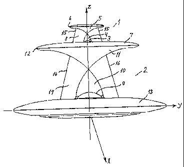
FIGURE 2 is a schematic representation of a sound reproduction device
according to the invention comprising two acoustic reflectors placed on top of
each other;
FIGURE 3 is a schematic, cross-sectional representation of a single
acoustic reflector system as used in the device according to the invention;
FIGURE 4 is a schematic, cross-sectional representation of a single
acoustic reflector corresponding to the one shown in Figure 3 but provided
with
an alternative acoustic generator;
FIGURES 5A through 5D show measured free field horizontal
directivities at the frequencies 2.5kHz, 5kHz, 10kHz and 20kHz of a sound
reproduction device according to the invention normalized relative to the
frontal
direction (0 degrees);
FIGURES 6A through 6D show measured free field vertical directivities
at the frequencies 2.5kHz, 5kHz, 10kHz and 20kHz of a sound reproduction
device according to the invention normalized relative to the frontal direction
(0
degrees); and
FIGURE 7 shows measured free field horizontal directivity at 20kHz for
the treble dome driver used in the sound reproduction device according to the
invention but with the driver conventionally mounted vertically in a 17 cm
wide
cabinet.
DETAILED DESCRIPTION OF THE INVENTION
In the following a detailed description of various embodiments of the
invention is given.
With reference to Figure 2 there is shown a sound reproduction device
with a directional characteristic of radiated sound energy differing
substantially
CA 02501162 2005-04-04
WO 2004/034732 PCT/US2003/027496
-7-
and in a controllable manner from an omnidirectional characteristic.
Specifically
the device shown in Figure 2 comprises two acoustic reflectors 1, 2 provided
with individual sound generators 3, 9 and placed on top of each other. The
radiators are dimensionally scaled according to the specific frequency ranges
to be radiated by each of the two reflectors. The reflectors are shown as
geometrically symmetric about the vertical XZ plane of the drawing, but it is
understood, that reflectors with an asymmetric geometry could in principle
also
be conceived and that, even though the reflectors are substantially
geometrically symmetric about the XZ plane, they may be provided with
different acoustic surface materials of fine structure of the various
reflecting
surfaces in order to obtain desirable deviation from symmetric directional
characteristics, for instance in order to meet certain specific requirements
in the
room, in which the device is actually used. A number of such possibilities
will
be mentioned in the following.
Furthermore it is possible to rotate the two reflectors 1, 2 relative to
each other about the longitudinal (Z) axis. Although the directional
characteristics of the two reflectors in most cases probably should be
substantially identical - as seen from the surroundings - there might be
circumstances where a certain attenuation of the radiation at large angles in
the horizontal plane relative to the XZ plane of could be beneficial for
instance
due to the presence of strongly reflecting surfaces in this direction. If such
reflections are predominantly present within one of the frequency ranges
radiated by each of the two radiators it could well be beneficial to rotate
one of
the reflectors relative to the other reflector assuming that the latter
radiates
frequencies at which said reflections are not disturbing.
Returning to the specific structure of the reflectors 1 and 2, these
structures are in principle similar apart from dimensional differences related
to
the specific frequency ranges (specific ranges of wavelengths) radiated by
each individual radiator. The radiators 1, 2 mainly include first and second
reflector surfaces 4, 10 and 5, 11 respectively for directing sound energy
radiated by sound energy generators 3, 9 outwardly towards the desired
listening positions or listening areas in the surrounding room. One specific
CA 02501162 2011-06-09
WO 2004/033732 PCT/US2003/027496
-8-
example of such reflector surfaces is described in detail in U.S. Patent Nos.
5,615,176 and 6,068,080,, according to
which the reflector surfaces are ellipsoidal. Each of the acoustic reflectors
furthermore comprises first and second baffle means 7, 13 and 8, 14
respectively for controlled modification of the directional characteristics of
the
reflector surfaces 4, 10 and 5, 11 respectively. Specifically, the first
baffle
means according to this embodiment of the invention extends substantially
normal to the longitudinal axis Z of the acoustic reflector at the end of said
first
reflector surface 4, 10 facing away from the second reflector surface 5, 11.
The
first baffle means is shown in Figure 2 with an upper surface which is
generally
planar but provided with slightly rounded portions towards the outer edge of
the
baffle. Other forms of the surface of the first baffle 7, 13 could however
also be
conceived in practice.
The second baffle means 8, 14 include generally planar front surfaces
facing in the X direction in the figure, i.e. the direction towards the
desired
listening positions or listening area. The location of the front surface of
the
second baffle means is also shown in Figures 3 and 4, and the front surface
defines the edge portions of the first reflector surfaces 4, 10 and a part of
the
edge portions of the second reflector surfaces 8, 14. As shown in Figure 2 the
shape of the second baffles as seen from the direction towards the listening
position (along the X axis) is trapezoidal, as indicated by the inclining edge
portions 15, 16 in Figure 2, but other shapes could in principle also be used.
Furthermore, although the front surfaces of the second baffle means 8, 14 are
planar over the major part of the front surface, it may have a desirable
effect on
the directional characteristic to provide rounded edge portions 15, 16.
As mentioned above, the dimensions of the various reflector surfaces 4,
10 and 5, 11 respectively and of the first and second baffle means 7, 13 and
8,
14 respectively are preferably chosen according to the specific frequency
range
of each individual acoustic reflector. Furthermore the ratio between these
dimensions could also be optimized for each individual acoustic reflector.
The sound energy to be directed towards the listening positions /
listening area is for each of the individual reflectors generated by at least
one
CA 02501162 2005-04-04
WO 2004/034732 PCT/US2003/027496
-9-
sound generator means a specific example of such means being indicated by
reference numerals 3 and 9 in Figure 2. Specifically, the generator means as
shown in Figure 2 are dome drivers corresponding for instance to those
conventionally used as tweeters (high-frequency radiators) in high-fidelity
loudspeaker systems. It is however understood that other types of acoustic
generators could also be used, such as cone drivers (for instance
electrodynamic), piezo electric drivers or so-called compression drivers, i.e.
a
driver, where the sound generator g (see Figure 4) supplies sound energy to
the surroundings via an acoustic transmission line, such as a tube r. The
possibilities are however by no means limited to the above mentioned types of
drivers.
The directional characteristics of the reflector can be affected by the
exact positioning of the generator means relative to the various surfaces of
the
reflector. This is indicated in Figure 3 (where the generator actually used is
the
above-mentioned dome driver covering a driver radiation area A0) and in Figure
4 (where the above-mentioned compression driver is used). In case of the
dome driver as shown in Figure 3, both the direction of radiation (i.e. the
orientation of the axis of symmetry through the driver and the dimensions of
the
reflector), as indicated symbolically in Figure 3 by the angle a and the
position
of the driver diaphragm relative to the X, Y and Z dimensions of the
reflector,
as indicated symbolically by the arrows A and B in Figures 3 and 4 are
important for the resulting directional characteristics of the reflector. In
case of
the compression driver as shown in Figure 4 the dimension represented by the
angle a above is irrelevant.
Of course, the exact shape of the reflecting surfaces 4, 10 and 5, 11
plays a major role in attaining the desired directional characteristic. With
reference to Figures 3 and 4, it has been found, but this is only to be
regarded
as an example, that in the case of the ellipsoidal surfaces mentioned
previously
is could be preferable to utilize a portion of a total ellipsoid such that the
reflector surface indicated by SR in these figures extends from a portion of
the
ellipsoid where the tangent of the ellipsoidal surface is substantially co-
parallel
with the longitudinal axis (Z) through the reflector and terminates at a
portion of
CA 02501162 2005-04-04
WO 2004/034732 PCT/US2003/027496
-10-
said ellipsoid where the tangent of the ellipsoidal surface is substantially
normal
to the longitudinal axis (Z).
As mentioned initially, not only will the directional characteristics be
determined by the geometry of the various surfaces of the reflectors but also
by
variations of the acoustical (reflective) properties of these surfaces or
chosen
portions of these surfaces. It is hence possible to adjust the directional
characteristics of the reflectors by providing either the total surface of the
reflector surfaces 4, 10 and 5, 11 respectively and/or the first and second
baffle
means 7, 13 and 8, 14 respectively or chosen portions hereof with a suitable
surface texture. It would also be possible to introduce acoustically absorbing
portions of the various surfaces for instance by providing patterns of
apertures
or slits through the surface and terminating with an acoustic absorbing
material
such as felt or mineral wool in a manner, that is well known within the art.
Also
portions of the reflector surfaces may be provided by diffusor means, for
instance in the shape of protrusions or other irregularities on the surfaces.
Referring now to Figures 5A through 6D there are shown free field
measurements of horizontal and vertical directivities at the frequencies 2.5
kHz,
5kHz, 10kHz and 20kHz obtained with a reproduction device of the kind
described above. For comparison the measured free field directivity at 20kHz
for the same treble dome driver unit used as sound generator as in the device
according to the invention but conventionally vertically mounted in a 17 cm
wide cabinet is shown in Figure 7.
Specifically, it is apparent from Figures 5A through 5D that the
horizontal directivity of the reproduction device according to the invention
is
fairly constant throughout the frequency range from 2.5kHz to 20kHz. Sound
energy is - as desired - predominantly radiated towards the frontal portion of
the horizontal plane, the directivity pattern is between a few dB and some 10
dB down at +/- 90 degrees and heavily attenuated in the rear portion of the
horizontal plane. The latter is as mentioned initially desirable in order to
attenuate reflection from a wall or other obstacle present behind the device,
which reflections will give rise to interaural differences close to zero. The
fairly
even distribution of sound energy throughout the frontal part of the
horizontal
CA 02501162 2005-04-04
WO 2004/034732 PCT/US2003/027496
-11-
plane at all measured frequencies is as mentioned initially desirable in order
to
obtain a uniform timbre over the entire area in front of the reproduction
device.
The horizontal directivity pattern obtained with the device according to
the invention at the frequency 20kHz can be compared with the corresponding
horizontal directivity pattern shown in Figure 7. It is immediately apparent
that a
much more uniform horizontal directionality is obtained at high frequencies
with
the device according to the invention than with a conventionally mounted dome
tweeter.
Referring now to Figures 6A through 6D, there is shown corresponding
measured free field directivities of the device according to the invention in
the
vertical plane measured at the frequencies 2.5kHz, 5kHz, 10kHz and 20kHz.
As stated initially it is generally desirable to attenuate reflections from
the floor
and ceiling between the sound source and the listening position as well as
from
a wall or other obstacle located behind the sound source. In a normal
listening
room, the reflections from the floor and ceiling will typically correspond to
elevation intervals of between +/- 30 to 60 degrees, and these reflections
will
arrive at the ears of a listener with approximately the same interaural
differences (time and/or intensity) as the direct sound, thereby possibly
leading
to undesired comb-filter effects. It is hence desirable to attenuate the
radiation
of sound energy within these vertical intervals (as well as the radiation of
sound
energy in the backward direction). It is apparent from Figures 6A through 6D
that the device according to the invention provides attenuation of radiated
sound energy both in the direction towards the floor (-30 to -60 degrees) and
in
the backward direction. Attenuation of radiated sound energy in the elevation
interval +30 to +60 degrees is especially apparent at frequencies from 5kHz
upwards, although it is not so pronounced as the attenuation of radiation
towards the floor and backwards.
Although the invention has been described in detail herein, it should be
understood that the invention is not limited to the embodiments herein
disclosed. Further, various changes, substitutions and modifications may be
made to the disclosure by those skilled in the art without departing from the
CA 02501162 2005-04-04
WO 2004/034732 PCT/US2003/027496
-12-
spirit or scope of the invention as described and defined by the appended
claims.