Note: Descriptions are shown in the official language in which they were submitted.
CA 02501200 2005-03-18
TITLE OF THE INVENTION:
AN APPARATUS AND METHOD FOR IMPROVING WORK SURFACE
DURING FORMING AND SHAPING OF MATERIALS
BACKGROUND OF THE INVENTION
The present invention relates to the field of forming and shaping of materials
by
various processes, including but not limited to cutting (e.g., shaping parts
by removing
excess material in the form of chips) and other types of machining, and more
particularly
improving surface finish and surface integrity of metals and other engineering
materials (e.g.,
polymers and various types of composite materials) formed and shaped through
such
processes by utilizing cryogenic cooling and other types of treatments,
including but not
fimited to heat treatment, chemical treatment, and mechanical treatment.
As used herein, the term "cutting" includes but is not limited to the
following
operations: tuming, boring, parting, grooving, facing, planning, milling,
drilling, and other
operations which generate continuous chips or fragmented or segmented chips.
The term
cutting does not include: grinding, electro-discharge machining, or high-
pressure jet erosion
cutting, i. e., abrasive operations generating veryfine chips that are not
well defined in shape,
e.g., dust or powder.
The term "integrity," as used herein, relates to quality, and more
specifically to the
desired state of residual stresses in the processed work surface, dimensional
accuracy
affected by wearing tools, and/or the absence of artifacts or other undesired
alterations of
surface that often result from the conventional forming or shaping processes.
There is a need in the manufacturing industries to produce more parts or
products
faster, i.e., to produce each part or product faster and without increasing
the cost per part or
-1-
CA 02501200 2007-05-11
comprising part quality. More specifically, there is a need for improved
methods which minimize the number and/or the extent of manufacturing steps
required to produce a specific, good quality part or product, such as soft
roughing, typically carried out before heat treatment, or finish grinding and
polishing/honing, typically carried out following heat treatment, or cleaning
steps, usually carried out on parts, machine tools, and in a work environment
due to the contamination caused by conventional machining fluids. Moreover,
there is an industrial interest in eliminating or minimizing the extent of
various
peening, burnishing, debuming, and localized deep-rolling operations
completing the forming or machining process cycle and used, in the case of
many metallic products, to enhance the mechanical surface integrity or
remove detrimental tensile stresses produced during forming or machining.
There also is a need for improved methods to accelerate forming and
machining operations, minimize capital expenses, e.g., the number of
machine tools required to reach specific production targets, and/or reduce the
cost of tooling and associated consumables.
U.S. Pat. No. 5,878, 496 (Liu, et al.) discloses a method for reducing
the number of machining steps while producing hard work parts with an
acceptable surface finish by an experimentation and modeling-based
manipulation of conventional machining parameters including tool feedrate
and nose radius. The patent does not, however, teach how to improve
productivity, increase cutting tool life, or reduce the roughness of a work
surface.
There exists a relatively large body of prior art publications pertaining
to some form of cryogenic spraying or jetting to eliminate cleaning
operations,
effect productivity of various types of cutting tools, and/or prevent
undesired
microstructural changes within machined surfaces. See, for example,
W002/096598A1 (Zurecki, et al.), W099/60079 (Hong), U.S. Pat. Publication
Nos.: 2003/0145694A1 (Zurecki, et al.) published August 7, 2003 and
2003/0110781A1 (Zurecki, et al.) published June 19, 2003 and U.S. Pat. Nos.:
5,901,623 (Hong), 5,509,335 (Emerson), 4,829,859 (Yankoff), and 3,971,114
(Dudley). However, none of these publications nor the other prior art
references discussed herein solve the problems or satisfy the needs
discussed herein.
-2-
CA 02501200 2007-05-11
U.S. Pat. No. 5,761,974 (Wang, et al.) discloses the use of a cryogenic
heat-exchanger in contact with the workpiece contacting edge of a cutting
tool, whereby direct contact between the cryogenic fluid and the workpiece is
avoided by use of the heat exchanger. U.S. Pat. No. 5,103,701 (Lundin, et al.)
discloses that cryogenic freezing of an entire workpiece may result in an
improvement of tool life when a sharp-edged diamond cutting tool is contacted
with ferrous work materials. The methods taught by these two patents
improve tool productivity, but the first method cannot effectively control
work
surface finish and integrity, and the second method requires extensive
machine tool modifications that would be unacceptably expensive in most
industrial applications.
U.S. Pat. No. 5,592,863 (Jaskowiak, et al.) discloses a method using
cryogenic cooling to produce discontinuous chips from a continuous chip
formed during machining of a polymer workpiece. By cooling the chip, rather
than the cutting tool or the polymer workpiece, the method does not improve
tool productivity or workpiece surface finish and integrity.
U.S. Pat. No. 6,622,570 B1 (Prevey, III) and U.S. Pat. Publication No.
2002/0174528A1 (Prevey, III) published Nov. 28, 2002 disclose methods for
eliminating undesired tensile stresses in a work surface that result from
various manufacturing operations (e.g., turning) and for imparting desired,
compressive stresses. Compressive residual stress in a work surface is
known to enhance fatigue strength and fatigue life of product parts while
reducing their sensitivity to stress corrosion cracking. An enhanced
resistance
to stress corrosion cracking and to other stress-accelerated forms of metal
corrosion is invaluable to metal component producers and users. The key
methods for correcting residual surface stress distribution (i.e., increasing
its
compressive component) include shot peening and laser peening, both of
which are known to deteriorate or damage work surface finish and increase
work roughness
-3-
CA 02501200 2005-03-18
if applied to their fullest extent. Further illustration of this probiem is
found in U.S. Pat. No.
6,658,907 B2 (lnoue, et al.) and in U.S. Pat. No. 6,666,061 B2 (Heimann), the
latter dealing
with deep-rolling, another stress fixing method applied to the surface of
manufactured parts.
These four patent publications show two critical and still unsolved issues
facing the industry:
(a) a frequent need for an additional, expensive manufacturing step fixing
residual surface
stresses and following the forming or shaping steps, and (b) the present trade-
offs between
the surface finish and the compressive stress imparted during the stress
fixing operations.
Clearly, there is an unsatisfied need for an improved forming, shaping and
machining
technique which would enhance surface finish and compressive stresses at the
same time
without requiring additional manufacturing steps.
Others have reported that during the conventional, non-cryogenic turning of
hard
steels, a sharp cutting edge improves the surface finish and/or somewhat
enhances the
desired compressive residual stresses, while a rounded or honed edge,
preferred from the
tool-life and productivity standpoint, makes the workpiece surface rougher
and/or less
compressed. J.D. Thiele and S.N. Melkote, Effect of cutting edge geometry and
workpiece
hardness on surface generation in the finish hard turning of AISI 52100 steel,
Journal of
Materials Processin4 Technoloav, 94 (1999) 216-226; and F. Gunnberg, "Surface
Integrity
Generated by Hard Tuming," Thesis, Dept. of Product Development, Chalmers
University of
Technology, Goteborg, Sweden, 2003. The impact of the honed edge geometry on
work
surface finish was observed to lessen with increasing work material hardness,
but no
conclusions were drawn regarding the prospect of controlling surface finish
and integrity by
modifying work surface hardness before or during machining operations while
maintaining an
acceptable tool life and high productivity.
Also, experimental roughness data which has been reported for very similar
machining conditions underlined the tentative nature of material hardness
effect suggested
by Thiele and Melkote, showing that the roughness increases whenever the work
hardness
-4-
CA 02501200 2005-03-18
increases. See, T. Ozel, Tsu-Kong Hsu, and E. Zeren, Effects of Cutting Edge
Geometry,
Workpiece Hardness, Feed Rate and Cutting Speed on Surface Roughness and
Forces in
Finish Turning of HardenedAlSl H13 Steel, Intemational Joumal of Advanced
ManufacturinQ
Technoloav (2003).
Thus, the prior art offers only fragmented and incomplete, if not
contradicting,
solutions to the industrial needs discussed above, and demonstrates the need
for a more
comprehensive method for reducing manufacturing steps and costs whi(e
improving work
surface finish and integrity. Specific areas that require a single,
comprehensive solution
include (a) effectiveness of cooling and hardening of cutting tools during
machining using
cryogenic jetting, which is preferred for its abiiity to reduce tool wear and
costs, increase
production rates, and eliminate cleaning steps from the manufacturing process,
(b)
application of cryogenicjetting to minimize roughness and maximize compressive
stresses of
work surface produced during machining so that no additional finishing steps
are required,
and (c) further modifications of work material properties before and during
cutting that
minimize machined surface roughness and, thus, eliminate the need for finish
grinding steps.
It is desired to have a method and an apparatus for improving the surface
finish and
integrity of a workpiece which satisfy the above needs and address the
problems discussed
herein.
It is further desired to have a method and an apparatus for improving the
surface
finish and integrity of a workpiece which overcome the difficulties and
disadvantages of the
prior art to provide better and more advantageous results.
It is still further desired to have a method and an apparatus for forming or
shaping a
workpiece which overcome the difficulties and disadvantages of the prior art
to provide better
and more advantageous results.
-5-
CA 02501200 2005-03-18
It is also desired to have a method and an apparatus for manufacturing
finished parts
and products which would eliminate one or more steps or elements required in
prior art
manufacturing processes and systems.
BRIEF SUMMARY OF THE INVENTION
Applicants' invention is a method and an apparatus for improving the surface
finish
and /or surface integrity of a workpiece formed or shaped with a tool. Another
aspect of the
invention is a method and an apparatus for forming or shaping a workpiece. Yet
another
aspect of the invention is a method and an apparatus for manufacturing a
finished part or a
finished product from a workpiece. Other aspects of the invention are a
workpiece formed or
shaped by the method and apparatus for forming or shaping a workpiece, and a
finished part
or a finished product manufactured by the method and apparatus for
manufacturing. The
invention also includes a nozzle for jetting an expanding jet of a cryogen to
a surface of a
workpiece.
A first embodiment of the method for improving at least one of a surface
finish and a
surface integrity of a workpiece formed or shaped with a tool, the workpiece
having a surface
hardness, includes increasing the surface hardness of the workpiece duting
forming or
shaping of the workpiece with the tool..("Surface finish" and "surface
integrity" are defined
and discussed in the Background of the Invention section above and in the
Detailed
Description of the Invention section below.) There are several variations of
the first
embodiment of this method.
In one variation, the surface hardness of the workpiece is increased by
cooling with a
cryogenic fluid at least a portion of the tool, or at least a portion of the
workpiece, or at least a
portion of the tool and at least a portion of the workpiece. In a variant of
this variation, the jet
of the cryogenic fluid impinges on a portion of the tool and a portion of a
surface of the
workpiece. There are several variations of this variant.
-6-
CA 02501200 2005-03-18
In one variation of the variant, the jet of the cryogenic fluid impinges on
the portion of
the tool at an impingement angle (a) greater than about 0 and less than about
90 . In
another variation, the jet of the cryogenic fluid impinges on the portion of
the tool at an
impingement angle (a) greater than about 30 and less than about 90 . In yet
another
variation, the jet of the cryogenic fluid impinges on the surface of the
workpiece at a spread
angle ((3) greater than about 0 and less than about 180 .
A second embodiment of the method for improving at least one of a surface
finish
and a surface integrity of a workpiece formed or shaped with a tool, the
workpiece having a
surface.hardness, includes increasing the surface hardness of the workpiece
prior to forming
or shaping the workpiece with a tool, or during forming or shaping of the
workpiece with the
tool, or both prior to and during forming or shaping of the workpiece with the
tool. In a
variation of this embodiment, the surface hardness of the workpiece is
increased by at least
one of a heat treatment, a chemical treatment, and a mechanical treatment.
A third embodiment of the method for improving at least one of a surface
finish and a
surface integrity of a workpiece machined with a cutting tool, the workpiece
having a surface
hardness, includes increasing the surface hardness of the workpiece during
machining of the
workpiece with the cutting tool, wherein the surface hardness of the workpiece
is increased
by cooling with a cryogenic fluid at least a portion of the cutting tool and
at least a portion of
the workpiece, and a jet of the cryogenic fluid impinges on a portion of the
cutting tool at an
impingement angle (a) greater than about 0 and less than about 90 , and the
jet of the
cryogenic fluid impinges on the surface of the workpiece at a spread angle (a)
greater than
about 0 and less than about 180 .
A fourth embodiment of the method for improving at least one of a surface
finish and
a surface integrity of a workpiece formed or shaped with a tool includes
multiple steps. The
first step is to provide a supply of a cryogen. The second step is to provide
a nozzJe adjacent
the workpiece. The nozzle includes multiple elements. The first element is at
least one inlet
-7-
CA 02501200 2005-03-18
adapted to receive a flow of the cryogen. The second element is an upstream
portion in fluid
communication with the at least one inlet, the upstream portion adapted to
receive at least a
portion of the flow of the cryogen from the at least one inlet. The third
element is a
downstream portion in fluid communication with the upstream portion and
adapted to receive
at least a portion of the flow of the cryogen from the upstream portion. The
fourth element is
at least one outlet in fluid communication with the downstream portion and
adapted to
receive and transmit from the downstream portion at least a portion of the
flow of the
cryogen. The third step is to deliver a portion of the cryogen to the at least
one inlet of the
nozzle, wherein the cryogen is at least partially separated within the
downstream portion of
the nozzle into a condensed phase portion and a vapor portion. The fourth step
is to jet at
least a portion of an expanding jet of the condensed phase portion and the
vapor portion
from the at least one outlet of the nozzle to the tool and a surface of the
workpiece.
In a variation of the fourth embodiment, the downstream portion of the nozzle
has at
least one diverging wall and at least one converging wall adapted to converge
on the
expanding jet. In a variant of that variation, the at least one diverging wall
has a diverging
angle and the at least one converging wall has a converging angle less than
the diverging
angle. In another variant, the diverging wall is open to an ambient
atmosphere.
Another embodiment is a method for improving at least one of a surface finish
and a
surface integrity of a workpiece machined with a cutting tool. This embodiment
includes
multiple steps. The first three steps of this embodiment are the same as the
first three steps
of the fourth embodiment of the method discussed above. The fourth step is to
jet at least a
portion of an expanding jet of the condensed phase portion and the vapor
portion from the at
least one outlet of the nozzle to the cutting tool and a surface of the
workpiece, wherein the
downstream portion of the nozzle has at least one diverging wall open to an
ambient
atmosphere and at least one converging wall adapted to converge on the
expanding jet, and
-8-
CA 02501200 2005-03-18
wherein the at ieast one diverging wall has a diverging angle and the at least
one converging
wall has a converging angle less than the diverging angle.
Another aspect of the invention is a method for forming or shaping a workpiece
having a surface hardness. A first embodiment of this method includes multiple
steps. The
first step is to provide a tool adjacent the workpiece, the tool adapted to
form or shape the
workpiece. The second step is to form or shape the workpiece with the tool.
The third step
is to increase the surface hardness of the workpiece during forming or shaping
of the
workpiece with the tool.
Another aspect of the invention is a workpiece formed or shaped by the above-
described method, the workpiece characterized by an improved surface finish,
an improved
surface integrity, or both an improved surface finish and an improved surface
integrity.
There are several variations of this aspect of the invention.
In one variation, the workpiece has a work surface roughness (Ra), wherein the
work
surface roughness (Ra) is equal to or iess than a theoretical low roughness
limit (Ra-t),
calculated as Ra-t=f2 / (32 r), where f is a cutting tool feedrate and r is a
cutting tool nose
radius.
In another variation, the workpiece has a formed or shaped work surface
characterized by an improved residual stress, said improved residual stress
being more
compressive, deeper extending, or both more compressive and deeper extending
than
another residual stress that would be obtained by forming or shaping the
workpiece without
increasing the surface hardness of the workpiece during forming or shaping of
the
workpiece.
In yet another variation, the workpiece contains at least one metallic alloy
having at
least one element selected from a group consisting of cobalt (Co), chromium
(Cr),
molybdenum (Mo), nickel (Ni), iron (Fe), tungsten (W), aluminum (AI), titanium
(Ti),
tantalum (Ta), niobium (Nb) and vanadium (V).
-9-
CA 02501200 2005-03-18
There are still yet other variations of this aspect of the invention. In one
such
variation, the workpiece is in a form selected from a group consisting of a
cast form, wrought
form, powder metallurgy form, and composite form. In another variation, the
workpiece
contains at least one polymer or at least one polymer-based composite. In yet
another
variation, the workpiece has a formed or shaped work surface characterized by
at least one
of an improved fatigue strength, an improved fatigue life, an improved stress-
cracking
resistance, and an improved corrosion resistance.
Another embodiment, a method for machining a workpiece having a surface
hardness, includes multipie steps. The first step is to provide a cutting tool
adjacent the
workpiece, the cutting tool adapted to shape the workpiece. The second step is
to shape the
workpiece with the cutting tool. The third step is to increase the surface
hardness of the
workpiece during shaping of the workpiece with the cutting tool, wherein the
shaped
workpiece is characterized by an improved surface finish having a work surface
roughness
(Ra) equal to or less than a theoretical low roughness limit (Ra-t),
calculated as Ra-t=f2 !(32
r), where f is a cutting tool feedrate and r is a cutting tool nose radius.
Another aspect of the invention is a method for manufacturing a finished part
or a
finished product from a workpiece having a surface hardness. One embodiment of
the
method includes multiple steps. The first step is to provide a tool adjacent
the workpiece, the
tool adapted to form or shape the workpiece. The second step is to form or
shape the
workpiece with the tool. The third step is to increase the surface hardness of
the workpiece
during forming or shaping of the workpiece with the tool. The fourth step is
to manufacture
the finished part or the finished product from the workpiece shaped or formed
with the tool.
In one variation of this method, the finished part or the finished product is
manufactured from the workpiece without using at least one additional
operation needed by
at least one other method for manufacturing a comparable finished part or a
comparable
finished product which the other method forms or shapes from a comparable
workpiece
-10-
CA 02501200 2005-03-18
having a comparable surface hardness without increasing the comparable surface
hardness
of the comparable workpiece during forming or shaping of the comparable
workpiece, said at
least one additional operation being selected from a group consisting of
grinding, polishing,
honing, deburring, peening, tumbling, burnishing, deep rolling, soft
annealing, soft
machining, soft shaping, soft forming, and work part cleaning.
Another aspect of the invention is a finished part or a finished product
manufactured
by the method described above and characterized by a reduced manufacturing
cost, said
reduced manufacturing cost being less than a higher manufacturing cost for a
comparable
finished part or a comparable finished product manufactured by at least one
other method
which forms or shapes a comparable workpiece having a comparable surface
hardness
without increasing the comparable surface hardness of the comparable workpiece
during
forming or shaping of the comparable workpiece.
Another embodiment of the method for manufacturing a finished part from a
workpiece having a surface hardness includes multiple steps. The first step is
to provide a
cutting tool adjacent the workpiece, the cutting tool adapted to shape the
workpiece. The
second step is to shape the workpiece with the cutting tool. The third step is
to increase the
surface hardness of the workpiece during shaping of the workpiece with the
cutting tool. The
fourth step is to manufacture the finished part from the workpiece shaped with
the cutting
tool, wherein the finished part is manufactured from the workpiece without
using at least one
additional operation needed by at least one other method for manufacturing a
comparable
finished part which the other method shapes from a comparable workpiece having
a
comparable surface hardness without increasing the comparabie surface hardness
of the
comparable workpiece during shaping of the comparable workpiece, said at least
one
additional operation being selected from a group consisting of grinding,
polishing, honing,
deburring, peening, tumbling, bumishing, deep rolling, soft annealing, soft
machining, soft
shaping, soft forming, and work part cleaning.
-11-
CA 02501200 2005-03-18
A first embodiment of the apparatus for improving at least one of a surface
finish and
a surface integrity of a workpiece formed or shaped with a tool, the workpiece
having a
surface hardness, includes means for increasing the surface hardness of the
workpiece
during forming or shaping of the workpiece with the tool. There are several
variations of the
first embodiment of this apparatus.
In one variation, the surface hardness of the workpiece is increased by
cooling with a
cryogenic fluid at least a portion of the tool, or at least a portion of the
workpiece, or at least a
portion of the tool and at least a portion of the workpiece. In a variant of
this variation, the jet
of the cryogenic fluid impinges on a portion of the tool and a portion of a
surface of the
workpiece. There are several variations of this variant.
In one variation of the variant, the jet of the cryogenic fluid impinges on
the portion of
the tool at an impingement angle (a) greater than about 0 and less than about
90 . In
another variation, the jet of the cryogenic fluid impinges on the portion of
the tool at an
impingement angle (a) greater than about 30 and less than about 90 . In yet
another
variation, the jet of the cryogenic fluid impinges on the surface of the
workpiece at a spread
angle (R) greater than about 0 and less than about 180 .
A second embodiment of the apparatus for improving at least one of a surface
finish
and a surface integrity of a workpiece formed or shaped with a tool, the
workpiece having a
surface hardness, includes means for increasing the surface hardness of the
workpiece prior
to forming or shaping the workpiece with the tool, or during forming or
shaping of the
workpiece with the tool, or both prior to and during forming or shaping of the
workpiece with
the tool. In a variation of this embodiment, the surface hardness of the
workpiece is
increased by at least one of a heat treatment, a chemical treatment, and a
mechanical
treatment.
A third embodiment of the apparatys for improving at least one of a surface
finish and
a surface integrity of a workpiece machined with a cutting tool, the workpiece
having a
-12-
CA 02501200 2005-03-18
surface hardness, includes means for increasing the surface hardness of the
workpiece
during machining of the workpiece with the cutting tool, wherein the surface
hardness of the
workpiece is increased by cooling with a cryogenic fluid at least a portion of
the cutting tool
and at least a portion of the workpiece, and a jet of the cryogenic fluid
impinges on a portion
of the cutting tool at an impingement angle ((x) greater than about 0 and
less than about 90 ,
and the jet of the cryogenic fluid impinges on the surface of the workpiece at
a spread angle
(R) greater than about 00 and less than about 1800.
A fourth embodiment of the apparatus for improving at least one of a surface
finish
and a surface integrity of a workpiece formed or shaped with a tool includes
multiple
elements. The first element is a supply of a cryogen. The second element is a
nozzle
adjacent the workpiece. The nozzle includes multiple sub-elements. The first
sub-element is
at least one inlet adapted to receive a flow of the cryogen. The second sub-
element is an
upstream portion in fluid communication with the at least one inlet, the
upstream portion
adapted to receive at least a portion of the flow of the cryogen from the at
least one inlet.
The third sub-element is a downstream portion in fluid communication with the
upstream
portion and adapted to receive at least a portion of the flow of the cryogen
from the upstream
portion. The fourth sub-element is at least one outlet in fluid communication
with the
downstream portion and adapted to receive and transmit from the downstream
portion at
least a portion of the flow of the cryogen. The third element of the apparatus
is a means for
delivering a portion of the cryogen to the at least one inlet of the nozzle,
wherein the cryogen
is at least partially separated within the downstream portion of the nozzle
into a condensed
phase portion and a vapor portion. The fourth element is a means for jetting
at least a
portion of an expanding jet of the condensed phase portion and the vapor
portion from the at
least one outlet of the nozzle to the tool and the surface of the workpiece.
In a variation of the fourth embodiment, the downstream portion of the nozzle
has at
least one diverging wall and at least one converging wall adapted to converge
on the
-13-
CA 02501200 2005-03-18
expanding jet. In a variant of this variation, the at least one diverging wall
has a diverging
angle and the at least one converging wall has a converging angle less than
the diverging
angle. In another variant, the diverging wall is open to an ambient
atmosphere.
Another embodiment is an apparatus for improving at least one of a surface
finish
and a surface integrity of a workpiece machined with a cutting tool. This
embodiment
includes multiple elements. The first three elements are the same as the first
three elements
of the fourth embodiment of the apparatus discussed above. The fourth element
is a means
for jetting at least a portion of an expanding jet of the condensed phase
portion and the
vapor portion from the at least one outlet of the nozzle to the cutting tool
and a surface of the
workpiece, wherein the downstream portion of the nozzle has at least one
diverging wall
open to an ambient atmosphere and at least one converging wall adapted to
converge on
the expanding jet, and wherein the at least one diverging wall has a diverging
angle and the
at least one converging wall has a converging angle less than the diverging
angle.
Another aspect of the invention is an apparatus for forming or shaping a
workpiece
having a surface hardness. A first embodiment of this apparatus includes
multiple elements.
The first element is a tool adjacent the workpiece, the tool adapted to form
or shape the
workpiece. The second element is a means for forming or shaping the workpiece
with the
tool. The third element is a means for increasing the surface hardness of the
workpiece
during forming or shaping of the workpiece with the tool.
Another aspect of the invention is a workpiece formed or shaped by the above-
described apparatus and characterized by an improved surface finish, an
improved surface
integrity, or both an improved surface finish and an improved surface
integrity. There are
several variations of this aspect of the invention.
-14-
CA 02501200 2005-03-18
In one variation, the workpiece has a work surface roughness (Ra), wherein the
work
surface roughness (Ra) is equal to or less than a theoretical low roughness
limit (Ra-t),
calculated as Ra-t=f2 / (32 r), where f is a cutting tool feedrate and r is a
cutting tool
nose radius.
In another variation, the workpiece has a formed or shaped work surface
characterized by an improved residual stress, said improved residual stress
being more
compressive, deeper extending, or both more compressive and deeper extending
than
another residual stress that would be obtained by forming or shaping the
workpiece without
using a means for increasing the surface hardness of the workpiece during
forming or
shaping of the workpiece.
In yet another variation, the workpiece contains at least one metallic alloy
having at
least one element selected from a group consisting of cobalt (Co), chromium
(Cr),
molybdenum (Mo), nickel (Ni), iron (Fe), tungsten (W), aluminum (Al), titanium
(Ti),
tantalum (Ta), niobium (Nb) and vanadium (V).
There are still yet other variations of the workpiece. In one such variation,
at least a
portion of the workpiece is in a form selected from a group consisting of a
cast form, wrought
form, powder metallurgy form, and composite form. In another variation, the
workpiece
contains at least one polymer or at least one polymer-based composite. In yet
another
variation, the workpiece has a formed or shaped work surface characterized by
at least one
of an improved fatigue strength, an improved fatigue lffe, an improved stress-
cracking
resistance, and an improved. corrosion resistance.
Another embodiment, an apparatus for machining a workpiece having a surface
hardness, includes multiple elements. The first element is a cutting tool
adjacent the
workpiece, the cutting tool adapted to shape the workpiece. The second eiement
is a means
for shaping the workpiece with the cutting tool. The third element is a means
for increasing
the surface hardness of the workpiece during shaping of the workpiece with a
cutting tool,
-15-
CA 02501200 2005-03-18
wherein the shape of the workpiece is characterized by an improved surface
finish having a
work surface roughness (Ra) equal to or less than a theoretical low roughness
limit (Ra-t),
calculated as Ra-t=f2 /(32 r), where f is a cutting tool feedrate and r is a
cutting tool
nose radius.
Another aspect of the invention is an apparatus for manufacturing a finished
part or a
finished product from a workpiece having a surface hardness. One embodiment of
the
apparatus includes multiple elements. The first element is a tool adjacent the
workpiece, the
tool adapted to form or shape the workpiece. The second element is a means for
forming or
shaping the workpiece with the tool. The third element is a means for
increasing the surface
hardness of the workpiece during forming or shaping of the workpiece with the
tool. The
fourth element is a means for manufacturing the finished part or the finished
product from the
workpiece shaped or formed with the tool.
In one variation of this apparatus, the finished part or the finished product
is
manufactured from the workpiece without using at least one additional
operation needed by
at least one other apparatus for manufacturing a comparable finished part or a
comparable
finished product which the other apparatus forms or shapes from a comparable
workpiece
having a comparable surface hardness without increasing the comparable surface
hardness
of the comparable workpiece during forming or shaping of the comparable
workpiece, said at
least one additional operation being selected from a group consisting of
grinding, polishing,
honing, deburring, peening, tumbling, burnishing, deep rolling, soft
annealing, soft
machining, soft shaping, soft forming, and work part cleaning.
Another aspect of the invention is a finished part or a finished product
manufactured
by the apparatus described above and characterized by a reduced manufacturing
cost, said
reduced manufacturing cost being less than a higher manufacturing cost for a
comparable
finished part or a comparable finished product manufactured by at least one
other apparatus
which forms or shapes a comparable workpiece having a comparabie surface
hardness
-16-
CA 02501200 2005-03-18
without increasing the comparable surface hardness of the comparable workpiece
during
forming or shaping of the comparable workpiece.
Another embodiment of the apparatus for manufacturing a finished part from a
workpiece having a surface hardness includes multiple elements. The first
element is a
cutting tool adjacent the workpiece, the cutting tool adapted to shape the
workpiece. The
second element is a means for shaping the workpiece with the cutting tool. The
third
element is a means for increasing the surface hardness of the workpiece during
shaping of
the workpiece with the cutting tool. The fourth element is a means for
manufacturing the
finished part from the workpiece shaped with the cutting tool, wherein the
finished part is
manufactured from the workpiece without using at least one additional
operation needed by
at least one other apparatus for manufacturing a comparable finished part
which the other
apparatus shapes from a comparable workpiece having a comparable surface
hardness
without increasing the comparable surface hardness of the comparable workpiece
during
shaping of the comparable workpiece, said at least one additional operation
being selected
from a group consisting of grinding, polishing, honing, deburring, peening,
tumbling,
bumishing, deep rolling, soft annealing, soft machining, soft shaping, soft
forming, and work
part cleaning.
Another aspect of the invention is a nozzle forjetting an expanding jet of a
cryogen to
a surface of a workpiece. A first embodiment of the nozzle includes multiple
elements. The
first element is at least one inlet adapted to receive a flow of the cryogen.
The second
element is an upstream portion in fluid communication with the at least one
inlet, the
upstream portion adapted to receive at least a portion of the flow of the
cryogen from the at
least one inlet. The third element is a downstream portion in fluid
communication with the
upstream portion and adapted to receive at least a portion of the flow of the
cryogen from the
upstream portion. The fourth element is at least one outlet in fluid
communication with the
downstream portion and adapted to receive and transmit from the downstream
portion at
-17-
CA 02501200 2005-03-18
least a portion of the flow of the cryogen. The fifth element is a means for
separating the
cryogen at least partially into a condensed phase portion and a vapor portion
within the
downstream portion of the nozzle.
A second embodiment of the nozzle is similar to the first embodiment but
includes an
intemal expansion chamber adapted to confine the expanding jet of the cryogen,
wherein the
nozzle is adapted to clamp a cutting tool having a tool rake surface.
There are several variations of the first embodiment of the invention. In one
variation,
the downstream portion of the nozzle has at least one diverging wall and at
least one
converging angle wall adapted to converge on the expanding jet of the cryogen.
In a variant
of this variation, the diverging wall has a diverging angle and the converging
wall has a
converging angle less than the diverging angle. In another variant, the
diverging wall is open
to an ambient atmosphere.
Another embodiment is a nozzle for jetting an expanding jet of a cryogen to a
surface
of the workpiece. This embodiment includes multiple elements. The first five
elements of
this embodiment are the same as the first five elements of the first
embodiment of the
nozzle. The sixth element is an intemal expansion chamber adapted to confine
the
expanding jet of the cryogen, wherein the downstream portion of the nozzle has
at least one
diverging wall open to an ambient atmosphere and at least one converging wall
adapted to
converge on the expanding jet of the cryogen, and wherein the diverging wall
has a diverging
angle and the converging wall has a converging angle less than the diverging
angle, and
wherein the nozzle is adapted to clamp a cutting tool having a tool rake
surface.
BRIEF DESCRIPTION OF THE DRAWINGS
The invention will be described by way of example with reference to the
accompanying drawings, in which:
-18-
CA 02501200 2005-03-18
Figure 1(1A, 1 B and 1 C) shows the key parameters of cryogenic fluid
impingement
on a cutting tool and a workpiece surface: impingement angle (a), spread angle
(P), tool feed
rate (f), depth of cut (d), the radius of tool curvature in contact with work
material (r),
impingement area (A), and the distance between the center of the impingement
area and the
work part surface (L), and more specifically,
Figure 1A is a schematic diagram illustrating a side view of one embodiment of
the
present invention wherein the cryogenic fluid jet impinges on a tool rake
surface at an
impingement angle (a);
Figure 1 B is a schematic diagram illustrating a top view of one embodiment of
the
present invention wherein the cryogenic fluid jet splashes on a tool surface
and then
impinges on the surface of the workpiece at a spread angle ((3);
Figure 1 C is a schematic diagram illustrating a top view of an embodiment of
the
present invention wherein the cryogenic fluid jet forms an impingement spot A
on the rake
surface of a cutting tool at a distance L from the work surface of the
workpiece;
Figure 2 (2A-2E) illustrates an apparatus and a method for impinging cryogenic
fluid
on a tool and work surface using free and confined-jet nozzles, and more
specifically,
Figure 2A is a schematic diagram illustrating a side view of an embodiment of
the
present invention using a free-expanding cryogenic fluid jet entraining an
ambient
atmosphere, such as air,
Figure 2B is a schematic diagram illustrating a side view of the downstream
part of
the nozzle in the embodiment of the present invention illustrated in Figure
2C;
Figure 2C is a schematic diagram illustrating a side view of an embodiment of
the
present invention using a dome-shaped, confined jet nozzle of the present
invention shown
in cross-section, located above the rake surface wherein the cryogenic fluid
jet impinges the
rake surface at an impingement angle (a);
-19-
CA 02501200 2005-03-18
Figure 2D is a schematic diagram illustrating a top view of an embodiment of
the
present invention using a rounded, dome-shaped, confined-jet nozzle of the
present
invention, shown in cross-section, located above the rake surface wherein the
cryogenic fluid
jet impinges on the surface of the workpiece at a spread angle (0);
Figure 2E is a schematic diagram illustrating a top view of an embodiment of
the
present invention using a rectangular, dome-shaped, confined-jet nozzle of the
present
invention, shown in cross-section, located above the rake surface wherein the
cryogenic fluid
contacts the rake surface over an impingement area A;
Figure 3 is a graph showing the effect of impingement angle (a), supply
pressure,
and flowrate of a cryogenic fluid on cooling rate of a cutting insert tool;
Figure 4 is a graph showing the effect of cooling method on the life of a tool
cutting
an as-sintered and prehardened ferrous powder metallurgy workpiece;
Figure 5 (5A and 5B) illustrates two aspects of the present invention during
finish-
tuming of prehardened bearing steel, 52100 grade, and more specifically,
Figure 5A is a graph showing the effect of cooling method on tool wear,
Figure 5B is a graph showing the roughness of work surface throughout the life
of the
tool; and
Figure 6 is a graph showing the effect of cooling method used during finish-
tuming on
residual stress distribution in and under the surface of a prehardened steel,
M50 grade.
DETAILED DESCRIPTION OF THE INVENTION
The present invention includes a method and apparatus for improving surface
finish,
or reducing surface roughness, and improving surface integrity of a work
material or
increasing compressive residual surface stress by increasing the hardness of
the work
material. Although the present invention is discussed herein in the context of
machining a
work material with a cutting tool, persons skilled in the art will recognize
that the invention
-20-
CA 02501200 2005-03-18
has broader application and may be used in many other shaping and forming
processes,
including but not limited to other types of machining, rolling, bending,
stamping, profiling,
drawing, etc.
The work material can be hardened prior to machining and other shaping
operations
by a suitable heat treatment, chemical treatment, or mechanical treatment,
including but not
limited to transformation hardening, e.g. quench-tempering of martensitic
steels, cryogenic
quenching treatments as exemplified by J.Y. Huang et al. (Microstructure of
cryogenic
treated M2 tool steel, Materials Science and Engineerina, A339, 2003, pp. 241-
244),
diffusion carburizing, nitriding, carbonitriding, baking, aging, laser
glazing, welding arc
(GTAW) solidification hardening, polymer cross-linking and ultra-violet light
curing, work
hardening via shot-peening or rolling, forging, cold extrusion and drawing,
cold pressing,
densification or coining, and combinations thereof, as well as other commonly
used
treatments selected for the type of work material. It should be understood
that many of these
work surface hardening operations can be carried out immediately before the
inventive
shaping step, e.g. immediately before the finish-cutting or forming tool
contacting the work
surface, in the same workpiece set-up, in the same manufacturing system, or in
the same,
automated transfer line. An example of hardening operations which can be
easily adopted
before the shaping tool are induction hardening and laser treatment of surface
in the stream
of gas containing carbon as taught by Kumar et aI. (US 6,454,877 B1).
The cryogenic cooling can be achieved by contacting the work material with a
cryogen in a liquid, vapor, or solid phase. The preferred inert cryogenic
liquids, which all boil
at temperatures much below the freezing point of water at 1-atmosphere
pressure, include
liquid nitrogen, liquid argon, liquid carbon dioxide, and liquid helium.
However, persons
skilled in the art will recognize that other cryogenic mixtures of liquids,
gases, and solid
particles could be used as the cryogen.
-21-
CA 02501200 2005-03-18
The preferred cryogenic cooling method should be highly localized and produce
a
short-lived hardening effect. By jetting or spraying a cryogenic fluid there
is no need to
freeze the entire workpiece, which would be expensive and impractical. The
hardening
surface treatment technique of the present invention can be used when it is
desired to have
a final product harder than the feedstock used for machining, while the
cryogenic cooling
technique can be used if it is desired to retain the initial material hardness
after machining.
Also, the work material can be hardened prior to machining operations by
surface treatment,
as well as during machining operations by cryogenic cooling to maximize the
surface finish
and surface integriiy of the machined part.
Another aspect of the present invention is an optimized method of jetting
cryogenic
fluid at a cutting tool, or another shaping or forming tool, and a workpiece
surface, which
method has been developed by trial and error to meet certain cooling and work
material
hardening requirements while simultaneously maximizing tool life, thereby
increasing
manufacturing productivity and reducing manufacturing costs, including the
costs of coolant
spent. Also, a new type of cryogenic nozzle for machining has been developed.
Thus, the
present invention includes a clean, cost-effective, accelerated-speed
manufacturing method
which improves surface finish and surface integrity of processed parts (even
when the parts
are hard) and allows users to skip multiple manufacturing steps.
Various observations and discoveries were made during Applicants' use of the
present invention on finish turning of metallic, composite, and polymer work
materials. Some
of these observations and discoveries are discussed below.
An expansion of a compressed liquid nitrogen (LIN) coolant, or another liquid
cryogenic coolant, into a 1-atmosphere pressure jet using a nozzle aimed at a
tool rake
surface results in a more effective tool cooling than contacting that tool
rake surface with
compressed LIN. While the exact cooling mechanism responsible forthis effect
is not clear,
Applicants believe that it may be explained by the lower temperature of the
decompressed
-22-
CA 02501200 2005-03-18
liquid droplets impacting the tool. The normal temperature of LIN at 1-
atmosphere is -320 F,
while the temperature of LIN compressed to 120 psig is -275 F (i.e., 45 F
higher).
Applicants observed that the cooling of a tool is most effective when the tool
surface is
impacted by a fast moving jet or spray of LIN at a pressure no higher than 1-
atmosphere.
Figure 1A shows a side view of one embodiment of the present invention wherein
a
fast moving cryogenic fluid jet 20 impinges on a tool rake surface 14 at 1-
atmosphere
pressure. The components include a cutting tool 12 (or cutting insert), the
tool rake surface
14, a toolholder 16, a tubular nozzle 18 issuing the jet 20, and a workpiece
22. Akhough
cooling of the tool rake surface 14 is the most preferred method, cooling of
other tool
surfaces, such as the major and minor or trailing flanks, also is within the
scope of the
present invention.
The tool rake surface 14 is the surface of the cutting tool 12 (or cutting
insert) which
extends behind the cutting edge and stays in contact with a material chip
sheared away from
the workpiece 22. (Rake surface is the cutting tool surface adjacent the
cutting edge which
directs the flow of the chip away from the workpiece. The rake surface may be
completely
flat, chamfered, or may have a more compiex, three-dimensional topography
produced by
the molding or an addition of a plate in order to provide an enhanced control
chip flow and/or
chip breaking.)
As used herein, the terms "cutting tool" and "cutting insert" are
interchangeable. A
cutting insert is an indexable, replaceable cutting tool made of a hard
material, e.g. WC-Co,
CBN, A1203, or Si3N4i having a cutting edge and a rake surface, and mounted on
a suitable
toolholder.
Figures 1 B and 1 C illustrate certain features of the embodiment shown in
Figure 1 A,
which features are discussed below. The arrows in Figures 1A-1 C show the
directions of
rotation of the workpiece 22, the tool depth of cut (d), feedrate (f), and the
supply of a
cryogenic fluid into the nozzle 18.
-23-
CA 02501200 2005-03-18
Figure 1 C shows the spray impact area designated as A. An increase of the
spray
impact area (A) on the tool rake surface 14 results in improved cooling of the
cutting tool 12.
However, increasing the distance between the rake surface and the exit of the
nozzle 18 to
increase the spray impact area reduces cooling efficiency if the jet 20
travels through air.
Applicants believe that, in addition to the drop in the mass-flux density or
impact density, the
observed effect results from the entrainment of air into the expanding jet and
an excessive
in-flight boiling of cryogenic droplets.
An increase in the jet impingement angle (a) located in the plane normal to
the tool
rake surface 14 from 0 (the tangential direction) to 90 (the normal
direction) results in
significantly improved cooling of the cutting tool 12 and, consequently, a
longer tool life or the
capability of cutting faster and/or cutting harder work parts which generate
more heat. Figure
1A shows an impingement angle (a) against the background of the cutting tool
12, toolholder
16, workpiece 22, and a tubular jetting nozzle 18. A large impingement angle
(a) is
necessary for an effective cutting of a hard or hardened workpiece, and the
effect of the
angle is proportional to the hardness of the workpiece.
An increase in the jet spread angle ((3) located in the plane of the tool rake
surface 14
reduces work surface roughness. Figures 1 B and 1 C illustrate the jet spread
angle (R)
against the background of a round cutting tool 12, toolholder 16, workpiece
22, and a tubular
jetting nozzle 18. The distance L between the impingement spot or spray impact
area A on
the tool rake surface and the work surface shown in Figure 1 C is not critical
since the
splashed jet entrains less air than a free jet discussed above. What is
critical is that the
spread angle (0) is sufficient for the splashed jet to reach at least the
entire length of contact
between the cutting tool and the workpiece. The contact length extends between
points b1
and b2 as shown in Figure 1 C. In the case of rounded tools or tools cutting
on the curvature
of a rounded corner, which is frequently encountered in finishing operations,
the contact
-24-
CA 02501200 2005-03-18
length b1-b2 can be calculated from the depth of cut (d), tool radius (r), and
tool feedrate (f)
shown in Figures 1 B and 1 C using the following equation:
V42_ 2
blb2 = l g~ (a cos p~ d+ a cos 2r f
Without wishing to be bound by any particular theory, Applicants believe that
the
surprising, desired effect of a sufficiently large spread angle (p) on work
surface finish is
apparently related to the chilling and hardening of the work surface, the
chilling and
hardening of the thin, trailing end of the work material chip, and preserving
the original
geometry of the trailing edge of the cutting tool, which controls the surface
finish but wears
faster without an efficient, cryogenic cooling.
The degree of work surface finish improvement resulting from increasing the
spread
angle (R) is inversely proportional to the initial hardness of the work
material. This is in
contrast to the effect of the impingement angle (a) on tool life which is
directly proportional to
the initial hardness of the work material. Understandably, differently shaped
tools (e.g.,
polygonal tools) also can be used in machining operations according to the
present invention
and form the desired values of impingement angle (a)and spread angle ((3).
A more or less precise control of the impingement angle (a)and the spread
angle (P)
is practical only if an expanding, cryogenic fluid jet is at least partly
confined above the
targeted rake surface. This is because a free-expanding, unconstrained
cryogenic jet
discharged from a simple, unconfined nozzle, e.g., a tubular and/or
converging, or even from
a much more precisely jetting, converging-diverging, nozzle with a round or
polygonal cross-
section, tends to broaden radially or "bush-out" on decompression from an
elevated supply
pressure to atmospheric pressure. The extent of the radial bushing is strongly
dependant on
the temperature and phase composition (vapor phase content) of the cryogenic
stream
entering the nozzle. Since the temperature and phase composition of a
cryogenic stream
-25-
CA 02501200 2005-03-18
are subject to difficult to avoid fluctuations, it is beneficial to use a
nozzle in which the
expanding jet is at least partially confined. Such an improved nozzle should
also maximize
the surface contact area or spray impact area (A) between the boiling
cryogenic fluid and the
tool rake surface and prevent pressure build-up over that boiling area, i.e.,
maintain an
essentially 1-atmosphere pressure.
Figures 2B-2E show an embodiment of the present invention using a confined jet
nozzle 32. To prevent radial bushing of a cryogenic fluid jet and entrainment
of warm,
ambient air (typical for free-expanding jets produced by simple nozzles, such
as in Figure
2A), the nozzle 32 of the present invention (shown in Figures 2B-2E) expands
the cryogenic
fluid from an elevated supply pressure to an atmospheric pressure inside a
dome 30 that is
located just above the tool rake surface 14.
Figure 2B illustrates the principle of fluid jet confinement. During the
expansion and
decompression inside the downstream part of the nozzle 32, the cryogenic jet
separates into
a vapor portion and a condensed phase portion, which typically is a liquid
stream, as shown
in Figure 2B. In some cases, the condensed phase portion may comprise fine ice
particles
or a cryogenic slush, such as in the case of expanding cold carbon dioxide
(C02) gas or
liquid. Due to higher density and inertia, the condensed phase portion tries
to continue
expanding along the original axis but is deflected and continues expansion
along the
converging wall 34. The converging angie 36 of the converging wall, as shown
in Figure 2B
relative to the original axis, must be less than the diverging angle 40 of the
diverging wall 42
to assure the desired fluid decompression and jet expansion.
Typically, the initial angle of the converging wall 34 may vary between 01 and
60 , but
the curvature of the converging wall can increase at some distance downstream,
and the
final converging angle 36 of the converging wall relative to the original axis
can be as large
as 90 . It is this final converging angle of the converging wall which
determines the jet
impingement angle alpha (a) and the tool cooling effect. The steeper it is the
better.
-26-
CA 02501200 2005-03-18
Typically, the diverging angle 40 can varyfrom 30 to 175 relative to the
original axis,
depending on other nozzle design considerations, with the limiting condition
that the
diverging angle is always larger than the converging angle 36. The net result
of so selected
wall angles is the capabiliiy of separating the vapor portion from the
condensed phase
portion (e.g., liquid), and expanding the condensed phase portion in the
desired direction
and under the desired angle. The result is quite important because the
separated condensed
phase portion (e.g., liquid) is significantly more effective in cooling than
is the vapor portion.
Figure 2C illustrates the operation of the confining nozzle 32 designed
according to
the principle described above and points out the expansion of the cryogen from
an elevated
supply pressure to atmospheric (1atm.) pressure inside a dome 30 or cavity of
the nozzle
which is located just above the tool rake surface 14. The gap between the
bottom edge of
the dome and the rake surface is sufficient to prevent undesired pressure
build-up inside the
dome. The front side of the bottom edge of the dome, which faces the workpiece
22, can be
carved or grooved in order to project the main portion of the cryogen in the
most desired
direction. The shape and size of the front groove or grooves can be selected
to obtain the
desired value of the spread angle (a). The height and the internal curvature
of the dome can
be selected to produce the desired jet impingement angle (a). Furthermore, the
spray
impact area or contact area (A) can be conveniently maximized by enlarging the
size of the
base of the dome.
When jetting a liquid-based cryogenic stream, the expansion of compressed
cryogen
inside the dome 30 produces a substantially colder liquid and vapor phase. Due
to a
significantly higher density, the liquid phase continues to expand in the
original direction
dictated by the orientation of the constricting orifice located upstream and
becomes deflected
on the intemal wall of the dome. Consequently, the liquid phase impinges on
the tool rake
surface 14 under the same angle as that of the line tangential to the
curvature of the dome.
Thus, the impingement angle (a) can be easily set by the curvature and the
elevation of the
-27-
CA 02501200 2005-03-18
dome, and making the impingement angle (a) steeper than, say, 30 or even 80 ,
therefore is
not difficult.
W hiie the liquid portion of the cryogenic fluid expands over the intemal
curvature of
the dome 30 and leaves the dome through the front groove, the vapor (which is
much less
dense than the liquid) is pushed back toward the tool rake surface 14 and the
gap between
the bottom of the dome and the rake. The nozzle 32 of the present invention
is, in essence,
a centrifugally phase-separating device which projects the most cooling,
liquid phase toward
the hottest part of the cutting tool, and removes the cold vapor through the
sides of the base
of the dome.
Figures 2D and 2E show a top view of two possible configurations of the nozzle
32 of
the present invention where the front part of the dome 30 can be terminated
either with a
spherical curvature or a flat-curved wall to produce a more or less
constricted stream of
liquid cryogenic fluid. Corresponding to the shape of the front part of the
dome can be the
shape of the constricting orifice located upstream - round for a spherically
curved dome and
slit-shaped for a flat-wall curved dome.
The nozzle 32 of the present invention fits well into a real lathe-machining
environment, where chips evolving from a machined work surface tend to
entangle around,
collide with, or jam in front of conventional coolant nozzles. The compact
design of the
nozzle allows for mounting it at the end of conventional clamps holding down
cutting inserts
or attaching a holding bolt to the back end of the nozzle, so that it becomes
an insert clamp
and a coolant nozzle at the same time.
Applicants observed that an increase in work material hardness reduces the as-
machined roughness of a work surface during the useful life of a cutting tool,
which is
desired, but tends to shorten the useful life of the cutting tool, which is
undesired. Surface
roughness is the most popular measure of surface finish, and it is desired to
maximize
surface finish or minimize roughness in finishing operations. When the surface
roughness in
-28-
CA 02501200 2005-03-18
turning is reduced to the low values typical for grinding operations, it is
possible to skip the
grinding step and shorten the entire manufacturing process, thereby generating
substantial
savings. The challenge facing the manufacturing industry is to improve surface
finish without
reducing cutting tool life, as reduced cutting tool life leads to increased
production costs and
poor production rates. If the cryogenic fluid impingement angle (a) is steep
enough, the
problem of short tool life during cutting hard work materials is reduced.
Work surface hardening that enhances surface finish (i.e., reduces roughness)
and
surface integrity (i.e., increases compressive stresses) can be permanent or
temporary,
lasting only as long as the material surface is cold and effective only during
machining
operations. A permanent prehardening of work surface can include heat-
treatment, diffusion
carburizing, nitriding, polymer cross-linking, etc. As Applicants observed,
the same work
material produces better surface finish if it is hardened by a permanent
treatment before
machining. This is an altemative way of improving surface finish that does not
involve
increasing the spread angle (R).
However, the combination of prehardening work material and an additional
hardening
of it during machining using cryogen sprayed under a sufficiently large spread
angle ((3) often
results in further improvements of surface finish. Applicants observed that if
the cryogenic
chilling is used on an already prehardened work material (e.g., steel hardened
by quenching
and tempering or carburizing), the as-machined surface roughness drops right
to the limit of
the conventionally calculated theoretical roughness (Ra-t), and if the
geometry of the trailing
edge of the cutting tool is correct, the as-machined surface roughness drops
even below the
conventional limit (Ra-t).
The ideal arithmetic average surface roughness (AA) in turning or the
conventional
Ra-t limit is usually calculated from tool feedrate (f) and tool nose radius
(r) as follows:
f2
R -' 32r
-29-
CA 02501200 2005-03-18
from C. Feng, An Experimental Study of the Impact of Turning Parameters on
Surface
Roughness, Paper No. 2036, Proceedings of the 2001 Industrial Engineering
Research
Conference of the Institute of Industrial Engineers (2001).
Although widely accepted, this calculation is only approximate, because tool
geometry and feedrate of a turning tool allow only for exact calculation of
the maximum peak-
to-valley roughness (Rt) and the ratio of Rt / Ra-t = m is simply an estimate
for typical
tuming conditions. Even though Applicants' experimental work in finish-tuming
shows that
the ratio (m) may vary from 3.6 to 7.8 ( per C. Feng), Applicants use herein
the expression
for Ra-t and m=4 as the normative limit for the ideal arithmetic average
surface roughness
(AA) in tuming.
2
R, = 8r and Ra_I = R, l m
The observations and discoveries made during Applicants' work on finish tuming
of
metallic, composite, and polymer work materials can be integrated in the five
qualitative
equations below, in which: R. - arithmetic average surface roughness of
machined surface,
H - hardness of work material during cutting operation, t -life of cutting
tool, a - nozzle-
controlled cryogenic jet impingement angle, A - nozzle-controlled area of tool
rake surface
that is impacted by boiling cryogenic fluid, Ho - initial hardness of work
material, OHP - an
increase in work material hardness as a result of optional prehardening step,
R- nozzle-
controlled cryogenic jet spread angle, f - tool feedrate during cutting, r -
tool nose radius,
R,4 - theoretical roughness limit for round cutting edge, n and m - constants
greater than
zero which can be determined from machining tests on specimens, and the sign "-
" denotes
proportionality.
-30-
CA 02501200 2005-03-18
f2 t ~A
Ra - mrH and H and
H -Ho+,~H~+n- R
Ho+r~H1~
hence,
f2
R~ .
nl=r= Ho+6LH p +n=
Hp+AH
p and
u-A
t
H4+AHp +ri
H o + AH p
Example 1:
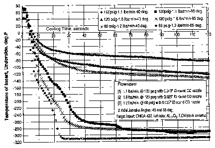
The effect of the cryogenic jet impingement angle (a) on cooling of a cutting
insert
was evaluated for various flowrates and supply pressures. Liquid nitrogen
(L{N) coolant was
jetted using two simple, tubular nozzles such as that shown in Figure 2A. The
internal
termination of the nozzles was shaped to form a converging-diverging (CD),
Laval-type fluidic
passage which can focus expanding cryogenic jets more precisely than straight-
wall or
converging-only fluid passages. The narrowest section of the throat of the
first CD nozzle
was 0.019 inches in diameter, and the second CD nozzle was 0.025 inches in
diameter. At
the supply pressure of 120 psig, the smaller nozzle jetted 1.1 lbs/minute of
LIN, and the
larger nozzle jetted 1.8 lbs/minute of LIN. An additional test with the larger
nozzle at the
reduced supply pressure of 60 psig showed that the expanding jet was more
confined or less
bushy, and its flowrate was 1.2 lbs/minute of LIN.
-31-
CA 02501200 2005-03-18
LlN jets produced by each nozzle were aimed at the rake of a cutting insert
typically
used in finishing operations: CNGA/CNMG-432 (ISO) made of a relatively non-
conductive
AI203-TiCN ceramic composite material. The axial distance between the exit of
each nozzle
and the rake surface was kept constant at 0.5 inches. Two impingement angles
(a) were
evaluated for each jetting condition: 400 and 85 . A micro-thermocouple was
placed right
under the insert, under its cutting nose, to monitor temperature changes
during the first two
minutes of LIN jetting from room temperature. The test results graphed in
Figure 3 show that
a steep jet impingement angle (a=85 ) is the most critical factor for a rapid
and effective
cooling of the cutting insert. The effect of jet bushing during expansion is
less important but
not neglectable - the more confined, 60-psig jets were more effective than the
120-psig jets.
Most surprisingly, the effect of LIN flowrate was found to be the least
important of the three
factors, indicating that the most cost-effective cryogenic fluid jet cooling
method must
optimize the impingement angle (a) and its confinement rather than simply
maximize flowrates.
The test was repeated with another popular cutting insert used in finish
turning
operations: CNGA/CNMG-432 made of a thermally conductive cubic boron nitride
(CBN)
cutting nose brazed into a conductive WC-Co carbide holder. At the steep jet
impingement
angle (a=85 ), cooling rates were found to be the same as for the non-
conductive ceramic
insert; the CBN/WC-Co cooling rate was only somewhat higher than before, and
only at the
lower impingement angle (a=40 ). Thus, the control of the jet impingement
angle (a) was
again found to be critical for cooling of the nose of the cutting tool,
necessary for an effective
and fast cutting of hard work materials.
-32-
CA 02501200 2005-03-18
Example 2:
Iron, graphite, copper, and nickel powders were premixed to obtain the FN-0208
(MPIF class) composition (0.8-0.9%C, 0.8%Ni, 2.0%Cu, bal.Fe, all on weight
basis), pressed
into powder metallurgy (P/M) disks, and sintered to achieve two different
density levels: 6.67
g/cm3 (6.67 Mg/m3), 'low-density' material, 14.5% porosity fraction, and 7.20
g/ cm3 (7.20
Mg/m), 'high-density' material, 7.7% porosity fraction. Half of the disks from
each density
group were subsequently case hardened by heat-treating using the conventional
procedures
for achieving a high-level apparent hardness - at least 30 HRC in the case of
the low density
material, and at least 40 HRC in the case of the high density material.
Surface machining of so prepared P/M disks was carried out on a 20 kW CNC
lathe,
constant speed operation, using the following parameters: (1) cutting speed -
1,000 fk/min.
(305 m/min. or 5.08 m/s); (2) feedrate - 0.007 inch/rev. (0.178 mm/rev.); and
(3) depth of cut
- 0.008 inches (0.203 mm). A"low-content", commercially available, uncoated
PCBN cutfing
insert was used, grade BN250 with 2 cutting edges (popular, brazed tip type).
Insert and
edge geometry were as follows: CNMA-433, 0.005-inch land width (0.127 mm wide
chamfer), -20 chamfer angle. The insert was mounted in the most commonly used
type of
steel toolholders characterized by -5 rake and -5 inclination angles. The
most conventional
method of cutting fluid cooling was used during machining which involved
flooding the insert
and the P/M disks. The fluid used, a 9 vol% of emulsified oil in water, was
flooded toward
the insert via tubing from a 20 psig (1.38 bar) supply pressure.
Surface finish of the machined P/M disks was evaluated using an arithmetic, Ra-
roughness meter, Surtonic 10, available from Taylor Hobson, Ltd. Material
hardness was
measured on a Vickers scale (kG/mm2) using conventional and microhardness
testers. The
results are set forth in Tabie I below. The reduction of surface roughness
(i.e., improvement
-of surface finish with increasing hardness) is clearly evident and shows that
a thermo-
mechanical surface hardening prior to machining is an effective measure for
superfinishing.
-33-
CA 02501200 2005-03-18
Table 1
P/M material condition: Apparent hardness, True (particle) Roughness,
HV hardness, HV Ra in microinches
As-sintered /soft disk, 99 186 44
low-density
As-sintered /soft disk, 127 189 43
hi h-densi
Heat-treated /hardened 306 567 11
disk, low-density
Heat-treated /hardened 399 569 8
disk, hi h-densit
Examale 3:
The as-sintered, soft P/M disks from Example 2 were surface machined using
liquid
nitrogen (LIN) cryogenic jet cooling and a tool-clamping nozzle with an
intemal expansion
chamber as shown in Figures 2C and 2D. At the LIN mass-flowrate of 1.8
lbs/minute, and
the supply pressure of 100 psig (6.89 bar), the nozzle produced a jet
impringing at the rake
surface under the impingement angle (a) equal 45 and spreading to the sides
under the
spread angle ((3) equal 90 . A cost-effective, commercially available, A1203-
TiC based, TiN-
coated (PVD), fine-grained biack ceramic cutting insert was used which had
four (4) cutting
edges and geometry specified as follows: CNGA-433, 0.008-inch land (0.200 mm
wide
chamfer), -25 chamfer angle. Apart from the different insert and cooling
method, all other
conditions were the same as in Example 2.
Table 2 compares the as-machined surface roughness of flood and LIN machined
disks and the life of cutting edge before an average tool flank wear (VbVe)
reaches the value
of 0.30 mm. It is clear that LIN cooling and hardening of the work material
and of the cutting
tool results in a substantial improvement of surface finish as well as tool
life.
Figure 4 compares the life of tools engaged in cutting of soft and prehardened
parts.
The life of tools is generally shorter as the material hardness increases, but
the life of the
LIN-cooled tools during machining of the hard parts is still ionger than the
life of the
-34-
CA 02501200 2005-03-18
conventionally, flood-cooled tools during machining of the soft parts. Thus,
it is cost-effective
to completely skip the soft machining steps from the manufacturing process,
then harden the
work surface, and perform the finish turning using LIN cooling.
Table 2
P/M material condition: Cooling method Roughness, Cutting edge life
Ra in microinches in
number of P/M
disks cut
As-sintered /soft disk, low- Flood 44 92
density
As-sintered /soft disk, low- LIN 24 337
density
As-sintered /soft disk, high- Flood 43 94
density
As-sintered /soft disk, high- LIN 23 499
density
Examale 4:
The effect of cryogenic jet spread angle (p) on surface finish was evaiuated
as a
function of work material hardness and plasticity. A medical cobalt-chromium
alloy, ASTM
F-type (Co-Cr-Mo-Ni-Fe-Si-W-Al-Ti), with the average hardness of 44 HRC was
selected for
tests as a mid-hardness, somewhat gummy-machining material. A popular bearing
steel,
52100 (1 %C-1.5%Cr-0.35%Mn-0.20%Si-BaI.Fe), was heat-treated by quenching and
low-
temperature tempering for the hardness of 60 HRC in order to represent the
group of hard
work materials. Both materials were cut using a 20 kW CNC lathe, constant
speed
operation, and the same type of commercially available cutting insert and
toolholder: an
inexpensive, commercially available, A1203-TIC based, TiN-coated (PVD), fine-
grained black
ceramic insert CNGA-432, 0.004-inch chamfer, -20 chamfer angle, and a-5 rake
/-5
inclination angie toolholder. The machining parameters were different for each
work
material, as shown in Table 3.
-35-
CA 02501200 2005-03-18
Two types of tool-clampingAnternal expansion chamber nozzles were used during
machining of the two work materials: the first, shown in Figure 2D, with a
spread angle ((3) of
90 and the second, shown in Figure 2E, with a spread angle ((3) of 25 . The
jet
impingement angle (a) was the same for both nozzles and equaled 45 . Each
nozzle was
supplied with LIN at the pressure of 100 psig, and each was spraying 1.8 lbs
of LIN per
minute.
As in the previous Examples, surface finish of machined parts was examined
using
an average arithmetic, Ra-roughness meter, Surtonic 10, available from Taylor
Hobson, Ltd.
Resultant work surface roughness, Ra, known also as AA or CLA roughness, was
compared to the theoretical surface roughness limit, Ra-t, estimated from the
following
normative equation: Ra-t = f2 /(8 m r), where: f-tool feedrate, r-tool nose
radius, and m -
roughness conversion constant assumed to be 3.9 for the present surface-finish
cutting
operations. The results in Table 3 below show that: (1) a large cryogenic jet
spread angle R
improves work surface finish, but its effect is inversely proportional to work
material
hardness; (2) harder and/or prehardened work materials produce a better
surface finish,
1/Ra, when the finish is estimated using the theoretical roughness limit, Ra-
t; and (3) the
combination of prehardened work material and the hardening effect of cryogenic
coolant
applied during cutting can produce work surface roughness levels which are
below the
conventionally accepted, theoretical roughness limit, Ra-t.
-36-
CA 02501200 2005-03-18
Table 3
Work material Co-Cr alloy 52100 bearin steel
Surface hardness 44 HRC 60 HRC
Cufting speed 900 ft/min 650 ft/min
Feedrate 0.002 inch/rev. 0.004 inch/rev.
Depth of cut 0.005 inches 0.008 inches
Theoretical roughness limit, 4.1 microinches 16.4 microinches
Ra-t,
Spread angle R of 90 25 90 25
c o enic nozuJe used
Roughness measured, Ra, 7.6 12.0 8.0 8.3
microinches
Roughness measured, Ra, 185 % 293 % 49 % 51 %
as a percent of the
theoretical roughness limit,
Ra-t
The low roughness levels shown in Table 3 and produced using LIN-hardening, as
well as thermal prehardening combined with LIN-hardening during tuming
operations, can
be fully appreciated when compared to the industrial standard roughness levels
set forth in
Table 4 below. Thus, Applicants' cutting method improves work surface finish
to the point at
which the conventional grinding and lapping operations may be eliminated and
the costs of
producing fine-finish parts are greatly reduced.
Table 4
Classification of machined surface finishes (ASM Handbook Desk Edition, 2001)
Roughness, R Approximate
relative cost
Class Mm pin Typical method of producing finish to produce
Super finish 0.10 4 Ground, microhoned, lapped 40
Polish 0.20 8 Ground, honed, lapped 35
Ground 0.40 16 Ground, lapped 25
Smooth 0.80 32 Ground, milled 18
Fine 1.60 63 Milled, ground, reamed, broached 13
Semifine 3.2 125 Ground, broached, milled, tumed 9
Medium 6.3 250 Shaped, milled, turned 6
Semirough 12.5 500 Milled, turned 4
Rough 25 1000 Tumed 2
Cleanup 50 2000 Turned 1
-37-
CA 02501200 2005-03-18
Example 5:
The effect of tool wear and cooling method on surface finish was evaluated as
shown
in Figure 5. The work material was the same 52100 bearing steel as in Example
3 but
tempered at higher temperature to reduce average surface hardness to 54 HRC.
Cutting
speed was increased from 650 ft/minute to 750 ft/minute, but the feedrate,
depth of cut,
theoretical roughness limit (Ra-t), the tooling, and the LIN supply method
were the same as
used on the 52100 material in Example 4. LIN jet impingernent angle (a) and
spread angle
((3) were 45 and 25 , respectively. The comparative flood machining run used
the flooding
method as in Example 2. Results show that the surface roughness of the LIN
machined
material is lower than in the case of flood cooling, even though the flank
wear of the LIN
cooled tool is less than the flank wear of the flooded tool. The intensity of
insert cooling by
LIN preserves the cutting edge, and a low-angle spread of LIN is sufficient
for improving
surface finish of the hard work material. Moreover, the actual roughness with
LIN falls below
the theoretical limit, Ra-t. Figures 5A and 5B show that flank wear or tool
nose flattening
alone cannot explain the low roughness effect with LIN. Table 5 compares the
surface finish
of the harder steels (see Example 4) and the softer steels (see Figure 5B)
machined with LIN
jetting under the same impingement angle (a) and spread angle (p). The harder
52100
surface, machined at a somewhat lower cutting speed, is smoother than the
other one,
indicating differences in the micro-plastic flow work material and chip around
the cutting
edge. This is additional proof that LIN jet-cooling during cutting, as well as
work surface
prehardening, are effective means of controlling surface roughness.
Table 5
Work surface hardness 60 HRC 54 HRC
Cufting speed 650 ft/min 750 ftlmin
Roughness measured, Ra, microinches 8.3 11
Roughness measured, Ra, as a percent of 51 % 67 %
theoretical roughness limit, Ra-t
-38-
CA 02501200 2005-03-18
Example 6:
Samples of 25 vol% glass filled nylon composite, as well as samples of plain
polymers made of polypropylene, high-density polyethylene (HDPE), cast
acrylic, and an
acetal homopolymer Deirin were prepared for finish end-milling and through-
hole drilling
tests using the LIN surface hardening method of the present invention. (Delrin
is a
registered trademark of E.I. Du Pont De Nemours and Company.) LIN jet was
impinged at
and around the tool-work surface contact zone under a steep impingement angle
(a) of 75
from the distance of 0.5 inches using a simple, but preciselyjetting, tubular
nozzle terminated
with a CD orifice. In the case of through-hole drilling, a second jet of LIN
was impinged at
the work material surface on the exit side of a drill bit. Results showed that
the LIN-
hardening significantly reduced stringy burrs typically forming on the surface
of these
polymers during machining. Exit-side burrs were also eliminated in the case of
through-hole
drilling by minimizing the plastic ruptures of the material in front of the
drill chisel approaching
the exit wall. The overall machined surface improvement was especially
significant when
compared to the conventional, dry machining procedure. The observed
improvement
enables machining operators to skip the subsequent deburring step and
eliminate the need
for the conventional, lubricating flood cooling which contaminates the surface
of polymeric
parts and necessitates additional cleaning steps.
Example 7:
The effect of cryogenic cooling on work surface integrity and, most
specifically, on
residual stress distribution was evaluated during outer diameter, finish hard
turning of alloy
steel rings. The rings were made of M50 grade steel (0.85%C-4.1 %Cr-4.2%Mo-1
%V-Bal.
Fe, wt. basis) quenched and tempered to the hardness of 63 HRC. The lathe and
toolholder
used were the same as in Examples 2-5. One tool feedrate of 0.003
inches/revolution was
used throughout all testing runs described below.
-39-
CA 02501200 2005-03-18
The first test, Test A, used the conventional flood cooling as detailed in
Example 2
and an expensive in use, commercially available, CBN cutting insert CNGA 432
KB5625.
The tool, cooling method, and cutting speed selected for Test A represent the
most typical,
standard industrial machining conditions that have been developed during
recent years by
trial and error and adopted to optimize tool life (i.e. tool cost and
productivity) against
resultant residual stresses which, ideally, should be highly compressive but
may become
more tensile when the tool is wom or the speed is higher. The next three
tests, B, C, and D,
used an inexpensive, Al203-TiC based cutting insert detaiied in Example 4. The
cutting
speed, corresponding to the production rate, that was selected for Tests B-D
was over 3.7-
times higher than the conventional, represented by Test A.
Table 6 presents the key conditions and cooling methods used for all four
tests.
Each cryogenic test used LIN as a cooling medium and a confining jet nozzle
type shown in
Figure 2E. The shape of the constricting orifice in that nozzle was
rectangular, and the size
was 0.080 inches by 0.025 inches plus or minus 0.010 inches. The impingement
angle (a)
was relatively steep (65 ) and the spread angle (p) was narrow (25 ) in order
to maximize
tool cooling effect over the entire length of tool-work contact arc. An
additional cooling and
hardening of work material was provided in Tests C and D by the simultaneous
use of a
secondary nozzle, a simple CD nozzle with the restricting orifice (throat)
diameter of 0.035
inches plus or minus 0.005 inches. The secondary nozzle was aimed at the
insert's rake and
cutting edge on the trailing side of the contact length, i.e. just downstream
of the axis of the
LIN jet formed by the primary, confining jet nozzle.
Residual stresses were measured on the rings machined under the presented
conditions using the standard X-ray diffraction method based on the change of
lattice
spacing as described in the "Handbook of Residual Stress and Deformation of
Steel", Edited
by G. Totten ef al., ASM Intemational, Ohio, 2002, pp. 112-113. An additional
procedure of a
repeated, step-wise X-ray measurement and electroetching a thin layer of
tested material
-40-
CA 02501200 2005-03-18
was used in order to define stress distribution deeper under the material
surface. The step-
wise procedure, commonly used in the manufacturing industries, has been
described by E.
Brinks et al. in publication "Residual Stresses - Measurement and Causes in
Machining
Processes", Annals of the CIRP, Vol. 31/2/1982, pp. 491-510. Results of the X-
ray
measurements of residual stress distribution are plotted in Figure 6.
Table 6
Test Cutting Depth of Cooling method Cryogenic nozzle Remarks
speed cut type(s) used
(ft/minute) inches
A 350 0.010 Emulsion flooded None Low heat input
from 28 psig generated by
back pressure machining
B 1300 0.010 LIN jetted from Confined jet High heat input
100 psig back nozzle shown in generated by
pressure Fi .2E machining
C 1300 0.015 LIN jetted from Two nozzies The highest
100 psig back used: [1] confined heat input
pressure jet nozzle shown generated by
in Fig. 2E and [2] machining
CD nozzle shown
in Fig. 2A
D 1300 0.010 LIN jetted from Two nozzles High heat input
100 psig back used: [1] confined generated by
pressure jet nozzle shown machining
in Fig. 2E and [2]
CD nozzle shown
in Fig. 2A
The plots show that residual stress is compressive in all four cases but the
use of
cryogenic cooling significantly increases the degree of the surface
compression and the
depth to which compressive stress can penetrate the material processed. The
best results
are obtained for Test C and Test D, both using the most cooling and hardening,
double
nozzle arrangement. Test C results in slightly less compressive stresses than
Test D
because the depth of its cut is 50% higher, i.e., the amount of heat entering
the material, or
the degree of material softening is higher. By maintaining work surface and
tool material
cool and hard, the disclosed cryogenic method and apparatus enable the use of
less
-41-
CA 02501200 2005-03-18
expensive tools which can cut faster and work more productively than the
conventional, CBN
tools. Moreover, in spite of increased cutting speeds, the disclosed cryogenic
method
enhances the compressive residual stress (i.e. surface integrity), thus
diminishing the need
for additional downstream operations such as polishing-away of the tensile-
stressed surface,
peening, tumbling, bumishing, deep-rolling, and similar manufacturing steps
conventionally
used to restore compressive stresses in machined and formed parts.
The present invention produces work surfaces characterized by an improved
surface
finish and surface integrity which is achieved without shortening the life of
the cutting tool.
This enables the manufacturing industry to skip certain up-stream and/or down-
stream
manufacturing steps, e.g., soft roughing, and grinding/polishing, peening,
burnishing, and
deburring. Also, when used in cryogenic machining, the present invention
allows the userto
skip the cleaning steps. In sum, the present invention provides a new
capability of producing
parts faster, at lower unit cost, and using less capital.
It should be recognized by those skill in the art, that the present invention
enables
improvements in product quality and reductions in production costs in numerous
industrial
segments including machinery, mining, energy, transportation, electric,
electronic, optical,
and medical component and equipment manufacturers. Examples of components
which can
be manufactured according to the present invention include metal sheet, strip,
extrusion,
profiled shapes and stampings, stamping tools, dies, molds, drills, rolls,
shafts, bearings,
bushings, spindles, rings, cylinders, valves, fasteners, fittings, wheels,
gears, blades, gages
and other measurement instruments, electrodes, heat-sinks, microchip
packaging, sputtering
targets, masks, laser mirrors and other optical components, medical implants
and
instrumentation, as well as diverse, dimensionally-accurate plastic and
composite
components.
-42-
CA 02501200 2005-03-18
Although illustrated and described herein with reference to certain specific
embodiments, the present invention is nevertheless not intended to be limited
to the details
shown. Rather, various modifications may be made in the details within the
scope and range
of equivalents of the claims and without departing from the spirit of the
invention.
-43-