Note: Descriptions are shown in the official language in which they were submitted.
CA 02501931 2005-03-22
PORTABLE SPRAY RACK
Background
Exterior home features, such as windows, skylights, curtain walls, and
doors, have typically been tested by manufacturers to determine the ability of
the
window to resist water penetration. However, due to insurance and
manufacturer needs, it has become increasingly important to determine the
water
penetration resistance of exterior home features already installed within a
home.
Typical spray racks used to perform water penetration testing are
generally not readily portable for use in the field (i.e., at the home where
the
exterior features) is to be tested). With this in mind, the make-shift spray
racks
conventionally used in the field are formed of polyvinyl chloride (PVC) pipe
with screw-in water spraying valves. When a test is to be performed in the
field,
the test administrator typically constructs a spray rack of selected lengths
from
the plurality of PVC pipe lengths he/she must carry to the site for testing.
The
rack is made to fit the particular size of the window to be tested and screw-
in
valves are placed along the PVC pipe lengths as required by the particular
test
standard being applied.
The assembled rack is then set with respect to the feature to be tested.
Traditionally, setting the rack includes taping the PVC pipe rack to at least
one
ladder, and the ladders) are placed a particular distance from the exterior
feature
to be tested. Placement of the spray rack is further exacerbated by the
presence
of bushes and other obstacles around the window, curtain wall, or door to be
tested. In many cases, due to the precise testing standard specifications that
must
be met (e.g., distance from nozzle to exterior feature, rate of water release
toward window, nozzle-to-nozzle spacing, etc.), the time to assemble the make-
shift spray rack is generally between 1 and 2 hours.
Once the spray rack is assembled, a garden hose is attached to the make-
shift rack. Water is directed to the exterior feature being tested at a
particular
rate and in a particular pattern from the valves as defined by the water
penetration test standard being employed. Following completion of the water
CA 02501931 2005-03-22
penetration test, the PVC pipe rack is disassembled and stored for subsequent
user. A typical PVC rack requires approximately 15-30 minutes to tear down.
As the PVC spray racks are used over and over again, the PVC pipe
becomes worn making water tight seals between the various pieces of PVC and
the valves more difficult to achieve. Namely, threaded connections become
stripped and the PVC pipes become brittle and often crack in cold conditions.
The deterioration of the condition of conventional PVC spray racks further
lengthens the assembly and disassembly time periods for the spray rack. These
time delays are further emphasized when a number of windows are tested at a
particular site and when various observers must be present during assembly and
testing for legal reasons.
Summary
One aspect of the present invention relates to a spray rack suitable for
testing a window in a building. The spray rack includes a plurality of spray
bars
and at least one stand-off leg. The plurality of spray bars each include at
least
one nozzle for spraying fluid. The at least one stand-off leg is coupled with
the
plurality of spray bars and includes a plurality of pre-measured settings each
corresponding to a distance between the at least one nozzle and the window.
The at least one stand-off leg is configured to be set at one of the plurality
of pre-
measured settings to interface with the building and to position the plurality
of
spray bars a desired distance from the window for testing the window by
spraying the fluid from the at least one nozzle of each of the plurality of
spray
bars toward the window.
Brief Description of the Drawings
Embodiments of this invention are better understood with reference to
the following drawings. The elements of the drawings are not necessarily to
scale relative to each other. Like reference numerals designate corresponding
similar parts.
Figure 1 is a perspective view generally illustrating one embodiment of a
spray rack positioned for testing a window.
2
CA 02501931 2005-03-22
Figure 2A is a top view of one embodiment of a cross bar with stand-off
legs of the spray rack of Figure 1.
Figure 2B is a front view of one embodiment of the cross bar with stand-
off legs of Figure 2A.
Figure 3 is a side view of one embodiment of a spray bar of the spray
rack of Figure 1.
Figure 4 is a side view of one embodiment of a spray bar extension for
use with the spray rack of Figure 1.
Figure 5 is a side view of one embodiment of a support leg of the spray
rack of Figure 1.
Figure SA is a detailed view of the portion of Figure 5 indicated at A.
Figure 6 is a top view of one embodiment of a partially assembled spray
rack positioned on the ground.
Figure 7 is a flow chart illustrating one embodiment of a method of using
a spray rack.
Figures 8A - 8D each illustrate one embodiment of a front view of a
cross bar and spray bars and/or spray extensions according to various
configurations of a spray rack.
Figure 9 illustrates a side view of one embodiment of a spray rack in use.
Figure l0A illustrates a top view of one embodiment of an open bag for
storing and transporting a spray rack.
Figure l OB illustrates a side view of one embodiment of a closed bag for
storing and transporting a spray rack.
Detailed Description
In the following Detailed Description, reference is made to the
accompanying drawings, which form a part hereof, and in which is shown by
way of illustration specific embodiments in which the invention may be
practiced. It is to be understood that other embodiments may be utilized and
structural or logical changes may be made without departing from the scope of
the present invention. The following detailed description, therefore, is not
to be
CA 02501931 2005-03-22
taken in a limiting sense, and the scope of the present invention is defined
by the
appended claims.
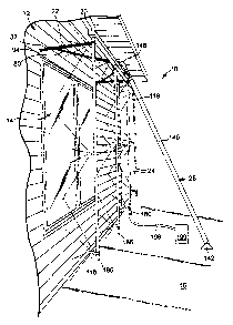
One embodiment of a spray rack 10 is generally illustrated in the
perspective view of Figure 1. Spray rack 10 is positioned against a building,
such as a residential, commercial, or other building, for testing a window 14
included on the exterior of building 12 to determine the level of water
penetration through and/or about window 14. In particular, spray rack 10
interfaces with ground 16 near building 12 as well as an exterior side of
building
12 in a manner suspending a portion of spray rack 10 in front of window 14.
Water is sprayed from spray rack 10 toward windows 14 in order to test the
window performance and the level of water penetration through window 14. In
one embodiment, spray rack 10 is configured to be spaced from window 14 and
is configured with proper dimensions in order to perform a standard water
penetration test, such as the ASTM E331-00 "Standard Test Method for Water
Penetration of Exterior Windows, Skylights, Doors, and Curtain Walls by
Uniform Static Air Pressure Difference." In one embodiment, spray rack 10 is
configured to perform any other of various tests for determining the integrity
of
window 14. In addition, spray rack 10 is configured to test various window
sizes
and windows 14 being positioned on various stories of building 12.
In one embodiment, spray rack 10 includes a cross bar 20, stand-off legs
22, spray bars 24, and a support leg 26. Stand-off legs 22, spray bars 24, and
support Ieg 26 each selectively attach to cross bar 20 to form spray rack 10.
In
particular, stand-off legs 22 each extend from cross bar 20 to interface with
building 12 during use. Spray bars 24 extend or hang from cross bar 20 in
front
of window 14 and are configured to deliver water to window 14 during use.
Support leg 26 extends from cross bar 20 to interface with ground 16 and to
support spray rack 10 above ground 16. Stand-off legs 22 are foldable or
collapsible with respect to cross bar 20, and spray bars 24 and support leg 26
are
selectively removable from cross bar 20 upon disassembly of the spray rack 10
for storage and transportation. In one embodiment, cross bar 20, stand-off
legs
22, spray bars 24, and support Ieg 26 are each formed of a generally rust-
proof
4
CA 02501931 2005-03-22
material or treated rust-proof material, such as anodized aluminum or other
suitable metallic or non-metallic material.
Figures 2A and 2B illustrate a top and front view, respectively, of one
embodiment of cross bar 20 with two stand-off legs 22. However, Figure 2B is
illustrated with only one stand-off leg 22 for clarity. Cross bar 20 includes
a
main elongated portion 30, first and second connection plates 32 and 34,
mounting blocks 36 and 38, stops 40 and 42, arches 44 and 46, and a plurality
of
male portions 48 of quick couplers. Main portion 30 is an elongated, hollow
member capped or closed at each end. In one example, main portion 30 is a
square pipe defining a top surface 50, a bottom surface 52 opposite top
surface
50, a front surface 54 extending between top and bottom surfaces 50 and 52,
and
a back surface 56 extending between top and bottom surfaces 50 and 52 opposite
front surface 54.
First and second connection plates 32 and 34 are spaced from one
another and are collectively centered longitudinally along main portion 30 of
cross bar 20. More particularly, each connection plate 32 and 34 is secured to
and extends from top surface 50 of main portion 30 away from main portion 30.
Each connection plate defines an aperture (not illustrated) to facilitate
selective
coupling of cross bar 20 with support leg 26.
First and second mounting blocks 36 and 38 are spaced from one another
and are collectively centered along the length of main portion 30. In
particular,
first mounting block 36 is spaced from second mounting block 38 a distance
further than first connection plate 32 is spaced from second connection plate
34,
and each mounting block 36 and 38 is coupled to top surface 50 of main portion
30. In this respect, first mounting block 36 is spaced from first connection
plate
32 in a direction opposite second connection plate 34. Similarly, second
mounting block 38 is spaced from second connection plate 34 in a direction
opposite first connection plate 32. In one embodiment, each mounting block 36
and 38 extends from top surface 50 a predetermined distance as required for
mounting stand-off legs 22. As such, as will be described further below, in
one
embodiment, each mounting block 36 and 38 includes a cavity or aperture
extending through mounting block 36 and 38 in a direction generally
5
CA 02501931 2005-03-22
perpendicular to the extension of main portion 30 with an orientation
generally
perpendicular to top surface 50 of main portion 30.
First and second stops 40 and 42 are coupled to top surface 50 of main
portion 30. In addition, first stop 40 is spaced from second stop 42 a
distance
S greater than the spacing between mounting blocks 36 and 38, and stops 40 and
42 are collectively centered longitudinally along main portion 30. In this
respect, first stop 40 is spaced from first mounting block 36 in a direction
opposite first connection plate 32. Second stop 42 is spaced from second
mounting block 38 in a direction opposite connection plates 32 and 34. In one
example, each stop 40 and 42 includes a block portion 60 and an angled portion
62. Block portion 60 is substantially rectangular and is coupled to top
surface 50
near back surface 56 of main portion 30. Angled portion 62 is triangularly
shaped and is secured to top surface 50 of main portion 30 near front surface
54.
As such, block portion 60 and angled potion 62 are laterally spaced from one
another. In one embodiment, block portion 60 and angled portion 62 are spaced
from one another in a manner to receive at least a portion of stand-off leg 22
between block portion 60 and angled portion 62.
First and second arches 44 and 46 are each coupled to and extend from
top surface 50 of main portion 30. In particular, first arch 44 is spaced from
first
stop 40 in a direction opposite first mounting block 36, and second arch 46 is
spaced from second stop 42 in a direction opposite second mounting block 38.
As such, first and second arches 44 and 46 are spaced from one another. In one
example, first arch 44 and second arch 46 are collectively centered
longitudinally along main portion 30. In one embodiment, each arch 44 and 46
is coupled to top surface 50 relatively near back surface 56 as opposed to
front
surface 54. Each arch 44 and 46 extends from top surface 50 as an inverted U
shape. In this respect, first arch 44 is a generally rectangular arch
extending over
top surface 50 so as to form an opening 64 between a portion of arch 44 and
top
surface 50. Second arch 46 similarly defines an opening 64. In one example,
each arch 44 and 46 includes an aperture (not illustrated) through a top
surface
of each arch 44 and 46 for selectively receiving a pin 66. With the above in
mind, in one embodiment, the positioning of first connection plate 32, first
6
CA 02501931 2005-03-22
mounting bock 36, first stop 40, and first arch 44 are collectively
longitudinally
symmetrical along top surface 50 of main portion 30 with respect to second
connection plate 34, second mounting block 38, second stop 42, and second arch
46.
Each of the plurality of male portions 48 of quick couplers extend from
bottom surface 52 of main portion 30. In one example, the plurality of male
portions 48 include a plurality of spray bar male portions 70 each configured
to
receive one spay bar 24. In one example, spray bar male portions 70 are evenly
spaced along main portion 30 of cross bar 20. In one example, spray bar male
portions 70 are evenly spaced two feet apart along main portion 30 in
accordance
with the ASTM E331 standard. Other spacing of spray bar male portions 70 is
also contemplated.
In one embodiment, the plurality of male portions 48 additionally
includes a gauge male portion 72. In one embodiment, gauge male portion 72 is
not evenly spaced along main portion 30 with respect to spray bar male
portions
70. Each of the male portions 48 are part of a quick coupler including a first
or
male portion and a second or female portion or any other suitable quick
couplers
capable of mechanically coupling two parts while allowing a fluid to flow
between the two parts, such as the quick couplers typically used between
pneumatic or hydraulic tools and supply hoses. In this respect, in one
embodiment, the plurality of male portions 48 of quick couplers are
alternatively
a plurality of female portions of quick couplers.
In one embodiment, each stand-off leg 22 includes a support member 80
and a main member 82. Support member 80 is an elongated member including a
first end 84 and a second end 86. An aperture (not shown) is formed through
first end 84 and is configured to permit rotatable coupling of first end 84 to
one
of mounting blocks 36 and 38 of cross bar 20. Second end 86 is opposite first
end 84 and defines an elongated slot 88. In one embodiment, spray rack 10
includes two stand-off legs 22 wherein one stand-off leg 22 is coupled to
first
mounting block 36 and the second stand-off leg 22, more particularly one
support member 80, is coupled to second mounting block 38.
7
CA 02501931 2005-03-22
Main member 82 is an elongated member defining a first end 90 and a
second end 92 opposite first end 90. In one embodiment, first end 90 includes
a
rubber tip 94 or other suitable skid-resistant tip configured to interface
with
building 12 (illustrated in Figure 1). An aperture (not illustrated) is formed
near
first end 90 and is configured to facilitate coupling of main member 82 to
support member 80. In particular, in one embodiment, a pin or other connector
96 extends through slot 88 of each support member 80 and into the aperture of
the respective main member 82. In this manner, main member 82 is rotatably
coupled to support member 80. In one embodiment, connector 96 is adjustable
or, more particularly, can be tightened or loosened. In one embodiment, when
connector 96 is tightened, main member 82 is generally not rotatable about
connector 96 or slideable along slot 88 of support member 80. However, in one
example, when connector 96 is loosened, main member 82 is rotatable about
connector 96, and connector 96 is slideable along slot 88 of support member
80.
1 S In one embodiment, a plurality of measured apertures 98 are formed
along main member 82 relatively near second end 92. Each of the plurality of
measured apertures are configured to correspond with a spacing of spray rack
10
from building 12 (illustrated in Figure 1 ). In particular, in one embodiment,
each of the plurality of measured apertures 98 correspond to a spacing of
spray
rack 10, in particular, spray bars 24, from building 12 a distance of 20
inches, 19
inches, 18 inches, etc. As such, each of the plurality of measured apertures
98
provide a pre-measured setting for spray rack 10. In one embodiment, each of
the plurality of measured apertures 98 are marked with measured indicia (not
shown) indicating the stand-off distance that would be achieved by utilizing
one
of the plurality of measured apertures 98. In one example, each indicia,
states
which measured aperture 98 corresponds to a spacing of 20 inches from window
14 at one of a plurality of inset distances commonly used with windows with
respect to exterior building 12. In one example, each of the plurality of
measured apertures 98 are positioned at a top surface of main member 82. In
one example, a block 100 is positioned along main member 82 between
connector 96 and the plurality of measured apertures 98 and is positioned
along a
back or outside surface of main member 82.
8
CA 02501931 2005-03-22
With the above in mind, each stand-off leg 22 is positioned to be
rotatably coupled to cross bar 20. More particularly, each support member 80
is
rotatable about its connection with mounting block 36 or 38 and each main
member 82 is rotatable about the respective connector 96 coupling to support
member 80. In this respect, in one embodiment, stand-off leg 22 is moveable
between a first or storage position as illustrated on the right hand side of
Figure
2B to a second or stand-off position as illustrated in the right hand side of
Figure
2A. In particular, in the storage position illustrated in Figure 2B, main
member
82 is placed between block portion 60 and angled portion 62 of stop 42 to at
least partially secure stand-off leg 22 relative to cross bar 20 in storage
position.
In addition, in one example, when in the storage position, block 100 is sized
and
positioned to fit within opening 64 of arch 46 such that pin 66 placed through
arch 46 and into block 100 also serves to selectively maintain stand-off leg
22 in
a stored position. The other stand-off leg 22 similarly is configured to
interface
with first arch 44.
Upon removal of pin 66 and movement of main member 82 from stop 40
or 42, support member 80 is rotated about its connection with mounting block
36
or 38 as generally illustrated on the left side of Figure 2A by arrow 102.
Simultaneously or subsequently, main member 82 is rotated about connector 96
as generally illustrated by arrow 104. Moreover, main member 82 is moved with
respect to support member 80 by sliding connector 96 along slot 88. In one
embodiment, connector 96 is tightened while stand-off leg 22 is in the stored
position and loosened in order to rotate main member 82 and slide connector 96
along slot 88. Support member 80 and main member 82 continue to be rotated
and moved until main member 82 can be slid at least partially through opening
64 of arch 44 or 46. Pin 66 is replaced through the respective arch 44 or 46
and
into main member 82 of the respective stand-off leg 22. In one embodiment,
connector 96 is tightened to facilitate the maintenance of stand-off leg 22 in
the
use or stand-off position.
In this respect, main member 82 is selectively coupled to cross bar 20 in
a stand-off position. In one embodiment, main member 82 can be slid through
the respective arch 44 or 46 a desired distance in order for pin 66 to
interface
9
CA 02501931 2005-03-22
with the one of the plurality of measured apertures 98 corresponding to the
desired positioning of spray rack 10 relative to window 14 (illustrated in
Figure
1). In on embodiment, in the stand-off position, support member 80 extends
from main portion 30 of cross bar 20 at an angle between 1 S° and
75°. Each
stand-off leg 22 is selectively movable from the stand-off position of Figure
2A
back toward the storage position of Figure 2B by simply reversing the steps
described herein. Accordingly, when in the storage position, stand-off legs 22
and cross bar 20 form a collectively elongated object providing for ease of
storage and transportation, while still being moveable to the stand-off
position of
Figure 2A for use during window testing. Other methods for coupling stand-off
legs 22 to cross bar 20 in manner providing for pre-measured and reliable
connection to cross bar 20 are also contemplated. For example, in one
embodiment, support member 80 is configured to interface with building 12
rather than main member 82.
Figure 3 illustrates one embodiment of one of the plurality of spray bars
24. Spray bar 24 is generally an elongated, hollow member defining a first end
110 and a second end 112 opposite first end 110. Spray bar 24 includes a
female
portion 114 of a quick coupler, a male portion 116 of quick coupler, and a
plurality of nozzles 118. Female portion 114 is secured to first end 110 of
spray
bar 24, and male portion 116 is secured to second end 112 of spray bar 24. In
particular, female portion 114 is configured to interact with a spray bar male
portion 48 of cross bar 20 upon assembly of spray rack 10. However, in other
embodiments, the positioning of female portion 114 and male portion 116 with
respect to first and second ends 110 and 112 is the opposite of that described
above. Each portion 114 and 116 is secured to the remainder of spray bar 24 in
a
manner providing for a generally waterproof or leakage proof seal to spray bar
24.
The plurality of nozzles 118 are each secured to a common side or edge
of spray bar 24 and are longitudinally spaced along spray bar 24. In one
embodiment, each nozzle 118 is evenly spaced along spray bar 24 in two feet
increments in accordance with ASTM E331-00. Other spacing of nozzles 118 is
also contemplated. Each of the nozzles 118 is secured to the remainder of
spray
CA 02501931 2005-03-22
bar 24 by a threaded attachment, sealant, adhesive, weld, and/or other
generally
leak proof attachment means. In one embodiment, the spray nozzles 118 are
made of stainless steel, brass, or other suitable material. In one embodiment,
each of the plurality of nozzles 118 is configured to spray fluid as a hollow
cone.
More particularly, in one embodiment, each of the plurality of nozzles 118 is
configured to spray a surface positioned 20 inches away from each nozzle 118
to
form a water or spray cone with an approximate 3 foot diameter in accordance
with ASTM E331-00. Use of other suitable nozzles is also contemplated.
Figure 4 illustrates one embodiment of a spray bar extension 120 for
optional inclusion with spray rack 10. Extension 120 is similar to spray bar
24.
As such, extension 120is a generally elongated, hollow member defining a first
end 122 and a second end 124 opposite first end 122. A female portion 126 of
the quick coupler is secured to first end 122 and a male portion 128 of a
quick
coupler is secured to second end 124 in a similar manner as described with
respect to female and male portions 114 and 116 of quick couplers with respect
to first end 110 and second end 112 of spray bar 24. At least one nozzle 130
extends from extension 120 relatively near second end 124. As such, extension
120 is configured to be coupled with spray bar 24 as desired by mating female
portion 126 of extension 120 with male portion 116 of spray bar 24 to thereby
extend the overall length of each spray bar 24. In one embodiment, extension
120 is primarily used in situations in which relatively laxge windows are
being
tested.
Figures 5 and SA collectively illustrate one embodiment of support leg
26 including a main portion 140, a foot 142, a plurality of telescoping
sections
144, and a connection plate 146. Main portion 140 is a hollow cylindrical,
square, or rectangular tube defining a first end 150 and a second end 152
opposite first end 150. Foot 142 is rotatably coupled to first end 150 of main
portion 140 and configured to interface with ground 16 (illustrated in Figure
1 )
during use of spray rack 10. In one embodiment, foot 142 includes a skid
resistant bottom surface 154 to prevent movement of spray rack 10 relative to
ground 16 during use.
11
CA 02501931 2005-03-22
The plurality of telescoping sections 144 each have a similar cross-
sectional shape as main portion 140, but are each sued progressively smaller
than main portion 140. The plurality of telescoping sections 144 are
positioned
partially within main portion 140 and extend or are extendable out second end
S 152 of main portion 140. In one example, the plurality of telescoping
sections
144 includes a first telescoping section 156, a second telescoping section
158,
and a third telescoping section 160 wherein each telescoping section 144 is a
generally elongated member. In one embodiment, first telescoping section 156
selectively fits within main portion 140, second telescoping section 158
selectively fits within first telescoping section 156, and third telescoping
section
160 selectively fits within second telescoping section 158.
In one embodiment, main portion 140 defines at least one aperture, with
a pin 162 or other suitable clamp or tension screw. Each telescoping section
144
includes a plurality of apertures 164 longitudinally spaced along the shaft of
each telescoping section. With this in mind, when first telescoping section
156
is positioned as desired with respect to main portion 140 (i.e., to extend a
desired
distance from second end 152 of main portion 140), pin 162 is placed through
the aperture of main portion 140 and into one of the plurality of aperture 164
of
first telescoping section 156 to maintain first telescoping section 156 in the
desired position. The ends of first telescoping section 156 and second
telescoping section 158 each similarly defines an aperture configured to
receive
a pin 162 to interface with one of a plurality of apertures 164 along the
shaft of
the second telescoping section 158 and the third telescoping section 160,
respectively. As such, the telescoping sections 144 can each be adjusted to
extend from the previous telescoping section 144 until support leg 26 has a
desired total length to interface with a particular window 14 (illustrated in
Figure
1 ). In one embodiment, support leg 26 is configured to support spray rack 10
for
testing windows on first, second, or other stories of building 12 (illustrated
in
Figure 1 ).
Connection plate 146 extends from the telescoping end of the final or
smallest telescoping section, i.e. third telescoping section 160. In one
embodiment, connection plate 146 is a generally L-shaped plate defining an
12
CA 02501931 2005-03-22
aperture 170 at a position opposite the connection of connection plate 146 to
the
respective telescoping section 144. In one embodiment, an additional pin 172
is
attached to connection plate 146 or third telescoping section 160 with a
lanyard
174 in order to maintain pin 172 proximate to aperture 170 for access during
assembly of spray rack 10. In one embodiment, support leg 26 is formed of T-6
aircraft grade aluminum.
Referring to the partially assembled view of spray rack 10 in Figure 6, in
one embodiment, spray rack 10 additionally includes a water supply connector
180. Water supply connector 180 includes a female portion 182 of a quick
coupler and a hose connector 184. Female portion 182 is configured to be
coupled with any one of the male portions 116 the plurality of spray bars 24
or
the plurality of extensions 120 if they are in use. Hose connector 184 is
configured to receive a hose 198 in fluid connection with a water supply 199
(illustrated in Figure 1 ), such as a gaxden hose connected to a home water
supply
and/or a separate water pump. In this manner, during use, water from water
supply 199 travels through hose 198 and into the respective spray bar 24. Due
to
the coupling of spray bars 24 with cross bar 20 to allow fluid communication
between one another, the water travels from first spray bar 24 through cross
bar
and into the other spray bars for dispersion out the plurality of nozzles 118.
20 In one embodiment, each spray bar 24 not coupled to water supply
connector 180 is coupled to a plug 186. In particular, each plug 186 includes
a
female portion 188 of a quick coupler and is configured to stop the flow of
fluids, such as water. As such, female portion 188 of each plug 186 is coupled
to
a male portion 116 of one spray bar 24 to decrease or prevent water flow out
of
the free ends of spray bars 24 through male portion 116. In one embodiment, in
which one or more spray bar male portions 70 of cross bar 20 are not coupled
with one of spray bars 24, those spray bar male portions 70 axe coupled to
female portion 188 of a respective plug 186 to similarly decrease or prevent
water flow out of the spray bar male portions 70 not coupled to a spray bar
24.
By plugging the end of spray baxs 24 and/or spray bar male portions 70 of
cross
bar 20, the water pressure within spray rack 10 is more easily maintained.
13
CA 02501931 2005-03-22
Moreover, in one embodiment, in order to facilitate maintenance and
monitoring of water pressure within spray rack 10, spray rack 10 includes a
pressure gauge 190. In one example, pressure gauge 190 includes a female
portion 192 of a quick coupler for attaching to gauge male portion 72 of cross
S bar 20. As such, pressure gauge 190 is in fluid communication with the water
traveling through cross bar 20 and outputs a measurement of the water pressure
of the water traveling through spray rack 10. As such, if during use the water
pressure falls below a desired level, the test operator will be notified that
a water
pump may need to be added to the water supply.
Figure 7 illustrates one embodiment of a method of using spray rack 10
generally at 200. At 202, spray rack 10 is assembled. In one embodiment, the
assembly of spray rack at 202 is substantially completed on ground 16 as
illustrated with additional reference to Figure 6. In particular, back surface
56 of
cross bar 20 is positioned on ground 16. At 204, the desired number of spray
bars 24 are coupled to cross bar 20 as well as a pressure gauge 190 being
coupled to cross bar 20. In particular, the number of spray bars 24 to be
attached
to cross bar 20 is dependent upon the size of window 14 to be tested.
For example, turning to the various configurations of spray rack 10
illustrated in Figures 8A - 8D, the width of the window to be tested is first
used
to determine how many spray bars 24 need to be coupled with cross bar 20. In
particular, in one embodiment, if the window to be tested has a width of 4
feet or
less, a spray rack configuration l0A as illustrated in Figure 8A may be
utilized
in which only two spray bars 24, namely the middle two spray bars 24 are
coupled to cross bar 20. However, if the window to be tested is wider, such as
up to 7 feet wide, all four spray bars 24 are generally attached to cross bar
20 in
spray rack configuration l OB as illustrated in Figure 8B. In one embodiment,
intermediate spray rack configuration (not illustrated) such as configurations
for
windows up to five feet wide could be used coupling three spray bars 24 to
cross
bar 20.
Once the overall width of the window is determined, the height of the
window is used to determine whether or not extensions 120 should be utilized.
In one embodiment, for windows with a height of 5 feet or less, extensions 120
14
CA 02501931 2005-03-22
are not utilized as illustrated in spray rack configurations 1 OA and l OB.
However, in one embodiment for windows having a height between 5 feet and 7
feet, an extension 120 is coupled to each spray bar 24 previously coupled to
cross bar 20 as illustrated in spray rack configurations l OC and l OD. Other
configurations of spray rack 10 including spray rack configurations sized to
test
windows greater than 7 feet by 7 feet are also contemplated.
In particular, each spray bar 24 is attached to cross bar 20 by interfacing
female portion 114 of spray bar 24 with spray bar male portion 70 of cross bar
20. By mating the female and male portions 114 and 70, each spray bar 24 is
quickly coupled with cross bar 20 such that all nozzles 1198 are directed away
from ground 16 in the assembly position of Figure 6. 'The coupling provided by
the quick coupler is a fluid flow coupling in which fluid can flow through
spray
bar 24 and into cross bar 20 or vice versa. In other embodiments, male coupler
may be included on each spray bar 24 and female couplers may be included on
cross bar 20. Similarly, if extensions 120 are determined to be necessary, an
extension 120 is coupled to each spray bar 24 that is coupled to cross bar 20.
In
particular, female portion 126 of extension 120 is coupled with male portion
116
of the respective spray bar 24. Upon coupling of each desired spray bar 24 and
extension 120, in one embodiment, pressure gauge 190 including a female
portion 192 of quick coupler is secured to gauge female portion 72 of cross
bar
20. In this respect, pressure gauge 190 is coupled with cross bar 20 in a
manner
allowing fluid flow between cross bar 20 and pressure gauge 190.
At 206, either a water supply connector 180 or a plug 186 is coupled to
the free end of each spray bar 24 or extension 120 opposite cross bar 20. In
the
illustration shown in Figure 6, in which no extensions 120 are utilized, a
water
supply connector 180 is coupled to the free end of one spray bar 24. In
particular, female portion 182 of water supply connector 180 is selectively
coupled to male portion 116 on the free end of a spray bar 24.
Water supply interface 184, such as a hose connector, of water supply
connector 180 is configured to interface with and be tightly secured the end
of a
common garden hose 198 (illustrated in Figure 1 ). All other remaining free
ends
of spray bars 24 are coupled with a plug 186. In particular, female portion
188
CA 02501931 2005-03-22
of each plug 186 is coupled to male portion 116 of remaining spray bars 24,
male portions 128 of remaining extensions 120, or spray bar male portions 70
of
cross bar 20. As plugs 186 generally decrease or prevent the flow of fluid out
the free end of each spray bar 24 or extension 120 not coupled to water supply
connector 180.
At 208, each stand-off leg 22 is set in place as required for the particular
window being tested. As such, as described above, pin 66 is removed from first
arch 44, and stand-off leg 22 is rotated from storage position to stand-off
position. As such, main member 82 is placed through opening 64 of first arch
44
and pin 66 is replaced through pin arch 44 and one of the measured apertures
98
of support member 80. In this respect, for ASTM E331-00 if the window being
tested is not inset with respect to the external surface of the building, pin
66 is
placed through the measured aperture 98 corresponding to a 20 inch test
distance
without a window inset. Similarly, if the window is inset an inch or more with
respect to the external surface of the building, the pin 66 is placed within a
different one of the measured apertures 98 as required to account for the
window
inset distance. Once the pin is in place, connector 96 is tightened to prevent
rotation of main member 82 about support member 80.
At 210, support leg 26 is attached to cross bar 20. In one embodiment,
while cross bar 20 is still positioned on ground 16, support leg 26 is
positioned
such that connection plate 146 is placed between first and second connection
plates 32 and 34 of cross bar 20. More particularly, aperture 170 of
connection
plate 146 is aligned with the aperture in each connection plate 32 and 34, and
pin
172 is manipulated to be placed through the aperture of first connection plate
32,
aperture 170 of connection plate 146, and finally through the aperture of
second
connection plate 34 in a manner rotatably securing support leg 26 to cross bar
20. Once support leg 26 is coupled to cross bar 20, the telescoping sections
144
of support leg 26 are adjusted such that support leg 26 extends from cross bar
20
a desired distance as required by the positioning of the window upon building
12. In particular, the plurality of telescoping sections 144 would be adjusted
to
form a longer support leg 26 for testing a second story window as opposed to
testing a first story window. In one embodiment, the entire assembly of spray
16
CA 02501931 2005-03-22
rack 10 and 202 is completed within a less than 5 minute time period, for
example, in a 2 minute time period.
At 212, the assembled spray rack 10 is lifted and set into position for
testing. In one embodiment, spray rack 10 is sufficiently light such that a
single
person grasping support leg 26 can lift the entire spray rack 10 from ground
16
up toward window 14 (illustrated in Figure 1 ). Upon lifting of support leg
26,
cross bar 20 rotates with respect to support leg 26 until spray bars 24 extend
from cross bar 20 in a substantially vertical manner. Spray rack 10 is
continued
to be moved toward window 14 and building 12 in a manner centering spray
rack 10 on the width of window 14 and placing stand-off legs 22 to interact
with
building 12 just above window 14 as illustrated with additional reference to
Figure 9. In the desired placement, rubber or skid resistant tips 94 of main
members 82 of stand-off legs 22 interface with building 12. Upon positioning
stand-off legs 22 to interface with building 12 and spray bars 24 to be
positioned
accordingly on window 14, support leg 26 is rotated until foot 142 interacts
with
ground 16 to support the entire spray rack 10 above ground 16. In one
embodiment, once set in position, the operator can release support leg 26 and
spray rack 10 is fully supported by ground 16 and building 12.
At 214, water supply 199 (illustrated in Figure 1) is connected to spray
rack 10. In one embodiment, water supply 199 is coupled to spray rack 10 via
hose 198 (illustrated in Figure 1 ). The end of hose 198 opposite the end
connected to water supply 199 is coupled to water supply connector 180, in
particular, hose connector 184. In one embodiment, water supply 199 can
additionally include pumps or other devices as needed to achieve the desired
water pressure through spray rack 10 during testing. At this point, spray rack
10
is positioned and ready for testing. At 216, the spray test is performed. In
one
embodiment, the spray test is performed according to water penetration testing
standards, such as ASTM E331-00. Accordingly, in one embodiment, nozzles
118 of spray rack 10 are properly positioned relative to window 14 such that
the
hollow spray cones emitted from nozzles 118 overlap as desired. In particular,
in one embodiment, the nozzles 118 are spaced on a two foot grid, and each
17
CA 02501931 2005-03-22
nozzle produces a hollow spray cone contacting building 12 and/or window 14
with a diameter of 3 feet inherently overlapping the hollow spray cones.
During testing, the operator observes pressure gauge 190 to monitor the
water pressure in spray rack 10. In one embodiment, spray rack 10 is
configured
to distribute about 5 gallons of water per hour during testing. Following
spray
testing, spray rack 10 is lowered from window 14 and disassembled in a manner
opposite that described in the assembly and setup process included in the
method
of use 200.
In one embodiment, a plurality of spray racks 10 are used in combination
to test larger windows. In one embodiment, spray rack 10 includes an
additional
cross bar interfacing with the otherwise free ends of spray bars 24, such as
interfacing with quick couplers. In one example, the additional cross bar
includes quick coupler portions on both the top and bottom surfaces of the
additional cross bar, and spray bars 24 are coupled with the quick coupler
portions on both surfaces of the additional cross bar. In one embodiment, at
least one quick coupler portion is attached to an end of main portion 30 of
cross
bar 20 for end-to-end attachment to a main portion 30 of another cross bar 20.
As such, spray racks according to embodiments of the invention are expandable
for use in commercial as well as residential settings. In one embodiment,
wheels
may be attached to stand-off legs 22 to facilitate lowering of spray rack 10
down
the side of a building.
As illustrated in Figures l0A and l OB, in one embodiment, a bag 250 is
provided for storing and facilitating transportation of disassembled spray
rack
10. In one example, bag 250 defines an inside surface 252 and an outside
surface 254. As illustrated in Figure 10A, when in the unfolded position, bag
250 lies in a substantially flat manner. Bag 250 additionally defines a
plurality
of pockets 256 open to inside surface 252 and each configured to receive at
least
one component of the spray rack 10 (i.e. cross bar 20, stand-off legs 22,
spray
bar 24, support leg 26, extension 120, water supply connector 180, pressure
gauge 190, and/or plugs 186). Each component can be easily slid into its
respective pocket 256.
18
CA 02501931 2005-03-22
Upon positioning of each component within its respective pocket 256,
bag 250 is folded along fold areas 258, which in one embodiment, are defined
between pockets 256. In one embodiment, closure straps 260 extend about the
outside surface 254 of bag 250. Bag 250 is folded along fold areas 258, and
closure straps 260 are tightened and buckled with buckles 262 to securely hold
bag 250 in the closed or folded position. In one example, bag 250 additionally
includes handles 264 and/or a shoulder strap 266 to facilitate transportation
of
bag 250 with spray rack 10 by a single individual. Accordingly, bag 250
provides for relatively easy transport and storage of spray rack 10. In one
embodiment, bag 250 is similar in size to a bag for common snow skis. In this
respect, bag 250 is sized for ease of transport on various forms of commercial
transportation, such as, vans, buses, airlines, etc.
Accordingly, a spray rack as described in the above embodiments of the
invention provides a time efficient, space efficient, and reliable means for
testing
exterior windows for water penetration. In particular, the stand-off legs
provide
a reliable means for setting the distance between the spray nozzles and the
window without requiring trial and error measurement of the distance and
adjustment of the spray rack set-up. In addition, the quick coupling of the
spray
bars to the cross bar provides for a quick, easy, and reliable assembly and
disassembly of the spray rack. Moreover, use of the support leg allows the
spray
rack to be supported against the building without generally requiring other
objects, such as ladders, etc., to support the spray rack regardless of the
height of
the window relative to the ground. The adjustable nature of the spray rack
also
allows the spray rack to be easily customized for use with a particular
window.
The collapsible nature of the spray rack promotes space efficient storage and
travel of the spray rack. Accordingly, the various features of the spray rack
provide a user-friendly and effective device for testing windows for water
penetration.
Although specific embodiments have been illustrated and described
herein, it will be appreciated by those of ordinary skill in the art that a
variety of
alternate and/or equivalent implementations may be substituted for the
specific
embodiments shown and described without departing from the scope of the
19
CA 02501931 2005-03-22
present invention. This application is intended to cover any adaptations or
variations of the specific embodiments discussed herein. Therefore, it is
intended that this invention be limited only by the claims and the equivalents
thereof.
20