Note: Descriptions are shown in the official language in which they were submitted.
CA 02502047 2005-03-23
STACKABLE BLOCK FOR
INSULATING CONCRETE FORM SYSTEM
FIELD OF THE INVENTION
[0001 ] The present invention relates to concrete form systems and, more
specifically, to
systems comprised of stackable foam block units. More particularly, the
invention relates to
insulating concrete form blocks that are reversibly stackable.
BACKGROUND OF THE INVENTION
[0002] In the field of constructing concrete walls, it is commonly known to
use forms
normally comprising a pair of panels arranged parallel to one another and
separated by a
distance. Concrete is then poured between the panels and allowed to set. After
the concrete is
set, the panels, usually made of wood, are removed. It is common to have ties
extending
between the two panels to ensure that the desired spacing is maintained.
[0003] The advent of insulating concrete form (ICF) systems has provided an
improvement
in concrete form systems. In ICF systems, the panels comprise slabs of
insulating foam between
which the concrete can be poured. Once set, the foam panels are left in place
thereby providing
both sides of the concrete wall with integral insulating layers. The foam
panels are separated by
ties that normally comprise two flange portions that are embedded in each of
the opposed foam
panels and a web portion extending there-between. The flanges can be embedded
by forming the
foam panels around them, by sliding the flanges into slots in the foam, or by
any other manner as
will be apparent to persons skilled in the art. The ICF systems are also
available in pre-made
blocks of standard dimensions that can be stacked both vertically and
horizontally to create any
desired configuration of form. An example of an ICF system is provided in U.S.
patent number
5,896,714, which shares common inventors with the present application (the
entire disclosure of
patent number 5,896,714 is incorporated herein by reference). In this patent,
a form block is
070959-359914 1 T0719-0008-CA
McCarthy Tetrault LLP TDO-RED #8268090 v. I
CA 02502047 2005-03-23
disclosed having various unique features. One of the key features is that,
once the blocks are
stacked, the tie flanges on each side of the form (and, therefore, the
concrete wall) are vertically
aligned. This results in a vertically continuous nailing surface for securing
wall finishing
material such as vapour barriers, additional insulation, wall boards and the
like.
[0004] Other ICF block systems are taught in the following U.S. patent
numbers: 4,229,920;
5,429,933; 6,253,523; 6,401,419; and 6,412,245 (the disclosures of which are
incorporated
herein by reference).
[0005] One of the problems associated with some known ICF block systems is
that the
blocks can only be used in one orientation. That is, they cannot be stacked
above another block
unless they are positioned in a specific inside/outside, top/bottom manner.
This often results in
wastage of product. Such wastage is particularly faced when a block is cut to
a smaller size and
the remaining portion cannot be used since their orientation cannot be
reversed.
[0006] Some of the prior art patents mentioned above disclose blocks that may
be reversed in
orientation. For example, U.S. patent number 5,896,714 teaches an ICF block
that can be
stacked in either orientation when rotated about its vertical axis. That is,
the block does not have
a designated inside and outside face. However, this block has a specific top
and bottom,
depending on the first course of the blocks that are laid. U.S. patent number
5,428,933, on the
other hand, does teach a block that is reversible along either the
longitudinal or vertical axis.
However, this reference does not allow for the ties of the block to be aligned
once stacked.
[0007] Thus, there exists a need in the art for a reversible ICF block that
overcomes at least
some of the deficiencies of the known blocks.
SUMMARY OF THE INVENTION
[0008] In one aspect, the present invention provides a concrete form block for
use in a form
system, wherein the block is stackable in either vertical orientation.
[0009] In another aspect, the invention provides an insulating concrete form
block made of a
pair of foam panels spaced apart by two or more ties and wherein the panels
are provided with
070959-359914 2 T0719-0008-CA
McCarthy Tetrault LLP TDO-RED #8268090 v. l
CA 02502047 2005-03-23
interlocking means to enable vertically and horizontally adjacent blocks to
engage each other and
an alignment means to ensure vertical alignment of the ties. The interlocking
means of each
panel are arranged opposite to the other of the block so as to allow the block
to be reversible, or
used in either vertical orientation.
[0010] In another aspect, the invention provides an insulating concrete form
block
comprising a pair of foam panels separated by two or more ties, wherein each
of the panels has
an interlocking means for engaging neighbouring blocks, and wherein the block
has a first plane
of symmetry extending diagonally between the top of one panel to the bottom of
the other panel
and a second plane of symmetry extending diagonally between the top right
corner to the bottom
le8 corner of the block. The panels of the block are provided with an
alignment means to ensure
vertical alignment of the ties when the blocks are stacked.
[0011] In another aspect, the invention provides a reversibly stackable
insulating concrete
form block, for use in a concrete form system, comprising: first and second
foam panels,
arranged opposed and parallel to each other and spaced apart by a
predetermined distance; and.
two or more ties extending perpendicularly between the panels to maintain the
panels in the
spaced apart orientation. In each panel, its top and bottom edges and left and
right ends have: a)
a first interlocking means for engaging a respective panel of a block
vertically adjacent thereto;
b) a second interlocking means for engaging a respective panel of a block
located horizontally
adjacent thereto; and c) a tie aligning feature for vertically aligning ties
of vertically adjacent
blocks. In the block, the panels of the block are arranged in opposite
orientation with respect to
each other whereby the block can be engaged with other vertically adjacent
blocks in either a
right-side up or upside-down orientation.
(0012] In another aspect, the present invention provides a reversibly
stackable insulating
concrete form block, for use in a concrete form system, comprising: first and
second foam
panels, arranged opposed and parallel to each other and spaced apart by a
predetermined
distance; and two or more ties extending perpendicularly between the panels to
maintain the
panels in the spaced apart orientation. Each panel includes a top edge, a
bottom edge, and left
and right ends. Also, in each panel: a) one of the top and bottom edges
includes a first tongue
070959-359914 3 T0719-0008-CA
McCarthy Tetrault LLP TDO-RED #8268090 v. l
CA 02502047 2005-03-23
extending longitudinally along the edge; b) the other of the top and bottom
edges includes a first
groove extending longitudinally along the other edge and being adapted to
receive a tongue
having the dimensions of the first tongue; c) one of the left and right ends
includes a second
tongue extending longitudinally along the end; d) the other of the left and
right ends includes a
second groove extending longitudinally along the other end and being adapted
to receive a
tongue having the dimensions of the second tongue; e) two or more projections
extending from
the edge having the first tongue; and f) two or more recesses provided on the
edge having the
first groove. The panels of the block are arranged in opposite orientation
with respect to each
other whereby the top of the first panel faces the bottom of the second panel
and the right end of
the first panel faces the left end of the second panel.
[0013] In a third aspect, a reversibly stackable insulating concrete form
block, for use in a
concrete form system is provided. The block comprises first and second panels,
arranged
opposed and parallel to each other and spaced apart by a predetermined
distance; and two or
more ties extending perpendicularly between said panels to maintain the panels
in said spaced
apart orientation. Further, on the first panel, on its top edge there is at
least one positive feature
for engaging a panel of a block vertically adjacent thereto; on its bottom
edge, there is at least
one negative feature for receiving a corresponding positive feature of the
adjacent panel. Also,
on the second panel, on its bottom edge, there is a compatible positive
feature to the positive
feature on the first panel; and on its top edge, there is a compatible
negative feature to the
negative feature on the first panel. The features are located on the
respective edges such that the
block can be engaged with other vertically adjacent blocks in either: a right-
side up orientation
with the negative feature of the first panel engaging a corresponding positive
feature on an
adjacent panel of a block below; or an upside-down orientation with the
compatible negative
feature engaging the corresponding positive feature on the adjacent panel.
[0014] In other aspects various combinations of sets and subsets of the above
aspects are
provided.
070959-359914 4 T0719-0008-CA
McCarthy Tetrault LLP TDO-RED #8268090 v. I
CA 02502047 2005-03-23
BRIEF DESCRIPTION OF THE DRAWINGS
[0015] The features of the invention will become more apparent in the
following detailed
description in which reference is made to the appended drawings wherein:
[0016] Figure 1 is a perspective view of a prior art form block;
[0017] Figure 2 is an end elevation of the prior art block of Figure 1;
[0018] Figure 3 is a perspective view of a prior art form constructed with a
plurality of form
blocks;
[0019] Figure 4 is a perspective view of a form block according to an
embodiment of the
present invention;
[0020] Figure 5 is a front elevation of the block of Figure 4;
[0021] Figure 6 is a plan view of the block of Figure 4;
[0022] Figure 7 is an end elevation of the block of Figure 4;
[0023] Figure 8 is a rear elevation of the block of Figure 4;
[0024] Figure 9 is a front elevation of a tie used in forming the block of
Figure 4; and
[0025] Figure 10 is a perspective view of an embodiment of the invention for
use in a corner.
DETAILED DESCRIPTION OF THE INVENTION
[0026] Figure 1 illustrates a prior art form block as described, for example,
in U.S. patent
number 5,896,714. As shown, the block 10 comprises opposing panels 11 and 12
made of an
insulating foam material as will be known to persons skilled in the art. The
panels 1 l and 12 are
joined together by means of a plurality of ties 13 extending there-between.
The panels 1 l, 12 are
maintained in an aligned and parallel manner, with the ties 13 extending
perpendicularly between
the panels. As shown in Figure 1 and as known in the art, the facing surfaces
of each panel 11
and 12 are preferably provided with a plurality of grooves so as to form a
stronger bond with the
concrete.
070959-359914 5 T0719-0008-CA
McCarthy Tetrauk LLP TDO-RED #8268090 v. l
CA 02502047 2005-03-23
[0027] Figure 2 illustrates an end view of the block of Figure 1 and more
clearly illustrates
the tongues 24 and grooves 26 of the prior art form block. Figure 2 also
illustrates the ties 13 as
known in the art. The ties comprise a central, planar web portion and two
flanges on opposite
ends of the web portion. The flanges are embedded within the foam panels 11
and 12 and are
preferably designed to extend over the entire height of each panel. In this
way, when the blocks
are stacked and the ties vertically aligned, the flanges provide continuous
strips to which
fasteners etc. may be attached.
[0028] Figure 3 illustrates a partial form constructed with a plurality of
blocks 10 arranged
both horizontally and vertically (i.e. stacked) according to the dimensions of
the wall required.
Also illustrated in Figure 3 is a corner block 20, which has a similar
construction to the linear
block 10 but includes a 90° corner. It will be understood that the
corner block can include any
desired angle apart from 90°. Figure 3 also illustrates at 22, the
alignment of the flanges of the
ties. As discussed above, by vertically aligning each tie when the blocks 10
are stacked, the
flanges form a continuous vertical strip, as shown at 22, to which various
types of fasteners may
be secured for attaching wall coverings etc. As can also be seen in Figure 3,
the outer surfaces of
the panels may be provided with features such as embossing or other such
indicia as taught in the
prior art to identify the locations of the flanges.
[0029] Returning to Figure 1 once more, the panels 11 and 12 are provided with
a number of
features that enable adjacent blocks to engage each other so as to ensure
that, once the form is
erected, the blocks are maintained in position. These interlocking features
comprise, firstly, a
longitudinally extending tongue 24 provided on the top of each panel 1 l and
12 and a
longitudinally extending groove 26 provided on the bottom of each panel. The
tongues 24 and
grooves 26 are designed so as to permit the tongues on the tops of the panels
of one block to
enter into the grooves on the bottoms of the panels of an adjacent block when
the blocks are
stacked. This engagement serves to restrict adjacent panels from moving with
respect to each
other. Further, each end of the panels is provided with either a tongue or
groove to engage the
panel of an adjacent block. However, as shown in Figure l, the tongues and
grooves on the sides
of the panels are oppositely provided. That is, on one side of the block, one
of the panels, 11, is
provided with a tongue 28 while the other panel, 12, is provided with a groove
30.
070959-359914 6 T0719-0008-CA
McCarthy Tetrault LLP TDO-RED #8268090 v. I
CA 02502047 2005-03-23
[0030] As can be seen, particularly in Figure 1, the block of the prior art
can be rotated about
its vertical, or transverse axis and still be stackable with adjacent blocks.
However, as can also
be seen, if the block 10 is rotated about its horizontal, or longitudinal
axis, and stacking of the
block on another is attempted, the required interlocking cannot be achieved.
This is due to the
fact that, as described above, the tops and bottoms of the blocks are
structured differently.
Specifically, the result of such stacking would be either two sets of grooves
or two sets of
tongues abutting each other.
[0031] As also shown in Figure 1, the panels of the blocks are provided with a
plurality of
projections 32 and corresponding recesses 34 on the tops and bottoms,
respectively, of each
panel 11, 12. The projections 32 and recesses 34 are features which serve to
locate vertically
adjacent blocks so as to ensure alignment of the ties 13 when the blocks are
stacked. As with the
tongues and grooves described above, the projections and recesses of the prior
art blocks inhibit
stacking if the blocks are not oriented in the same direction. It will be
appreciated that the
features may be provided as complementary "positive" and "negative" features
formed to mate
with each other. As noted in more detail below, a "positive" feature,
generally, is any outward
formation on the edge of the panel, while a "negative" feature, generally, is
any inward
formation on the edge.
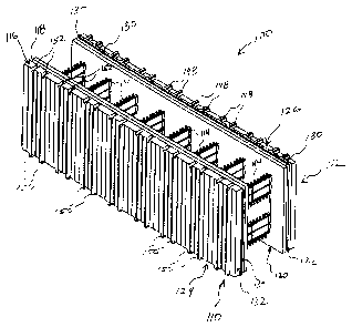
[0032] Figures 4 to 8 illustrate an embodiment of the present invention.
Referring first to
Figure 4, a foam form block 100 is shown in perspective. As can be seen, the
block has some
features of the prior art block discussed above and as more specifically
described in U.S. patent
number 5,896,714 (the entire disclosure of which is incorporated herein by
reference). The
block 100 is comprised of a pair of foam panels 110 and 112, arranged in a
parallel and opposed
manner. The panels 110 and 112 are maintained a specified distance apart by
means of a
plurality of ties 114 extending there-between. Each block is provided with at
least two ties, and
preferably a plurality of ties, with each tie provided longitudinally spaced
along the length of the
block as is known in the art. The ties will be discussed further below.
[0033] It is notable that the panels 110 and 112 have top and bottom edges and
right and left
ends, each including either a tongue or groove, as will be described further
below. Each of the
070959-359914 7 T0719-0008-CA
McCarthy Tetrault LLP TDO-RED #8268090 v. !
CA 02502047 2005-03-23
tongues and grooves serve, as described above, to interlock the panels of one
block to panels of
other blocks, located vertically or horizontally adjacent thereto. It will be
understood that the
terms "top", "bottom", "right", and "left" are used herein purely for the sake
of convenience in
refernng to the figures and that use of such terms is not intended to mean
that a block must have
any particular orientation. The tongue can be viewed as a "positive" feature
extending from the
surface of an edge, while the groove can be viewed as a "negative" feature
extending into the
surface of an edge.
[0034] As shown in Figures 4 to 8, the top longitudinal edge 116 of panel 110
is provided
with a groove 118 extending along the length of the edge 116. Groove 118 is
positioned within
the thickness of the panel 110. However, in other embodiments, it may be
positioned anywhere
across the thickness of the panel. Similarly, the bottom longitudinal edge 120
of the opposite
panel 112 is also provided with a groove 122 that is identical to groove 118
in both dimensions
and position along the width of panel 112.
[0035] The bottom longitudinal edge 124 of panel 110 and the top longitudinal
edge 126 of
panel 112 are provided with tongues 128 and 130, respectively, which extend
along the lengths
of the edges 124 and 126. The tongues 128 and 130 are sized and located so as
to engage the
grooves 118 and 122 described above, when blocks are stacked on top of each
other in the
process of erecting a form. For example, the tongue 128 of panel 110 would
engage the groove
118 of a similar panel underneath with a similar engagement taking place
between the tongue
130 of panel 112 and a groove 122 of an adjacent panel. In this manner,
vertically adjacent
blocks are secured together when stacked.
[0036] In order to assist in securing horizontally adjacent blocks together,
the panels of the
blocks are provided with a further tongue and groove structure, similar to
that described above.
As illustrated in Figures 4 to 8, the right end 132 of panel 110 is provided
with a groove 134
extending the entire height of the panel. The left end 136 of panel 110 is
provided with a tongue
138 being dimensioned to be received within a groove similar to 134 of a
horizontally adjacent
panel. Similarly, the right end 140 of panel 112 is provided with a tongue 142
while the left end
144 of panel 112 is provided with a correspondingly dimensioned groove 146. As
indicated
070959-359914 8 T0719-0008-CA
McCarthy Tetrault LLP TDO-RED #8268090 v. 1
CA 02502047 2005-03-23
previously, the combination of tongues 138 and 142 and grooves 132 and 146
allows
horizontally adjacent blocks to be engaged together.
[0037] As shown in Figures 4 to 8, the blocks 100 of the invention are also
provided with a
plurality of projections (as positive features) and recesses (as negative
features), described
further below, for ensuring that the ties 114 of stacked blocks are vertically
aligned. Refernng to
Figures 4 to 8, the top edge 126 of panel 112 of the block 100 is provided
with a plurality of
projections 148. The projections 148 are preferably elongate and extend
transversely from the
tongue 130 to the external face of the panel 112, the external face being that
surface facing away
from panel 110. The projections 148 are provided in pairs, one on each side of
a tie 114. The
spacing between adjacent pairs of projections 148 is preferably greater than
the spacing between
respective projections 148 of a pair. The bottom edge 124 of panel 110 is also
provided with
pairs of projections 150 arranged in the same manner and having the same
dimensions and
positioning as projections 148.
(0038] As shown more clearly in Figures 5 and 8, the top edge 116 of panel 110
and the
bottom edge 120 of panel 112 are, in turn, provided with recesses 152 and 154,
respectively,
which are adapted to receive projections 148 and 150 of vertically adjacent
panels. Recesses 152
and 154 are provided in pairs, in the same manner as the projections, wherein
each recess of each
pair is located one on opposite sides of a tie 114. Further, as with the
projections, the recesses
152 and 154 are elongate and extend from the longitudinal grooves 118 and 122,
respectively, to
the external faces of the panels 110 and 112.
[0039] The projections 148 and 150 are adapted to mate and to be engaged in
recesses 152
and 154 when two blocks 100 are stacked above each other. For example, if a
bottom block is
provided in the orientation as shown in Figures 4 to 8, that is with the top
edge 116 of panel 110
extending upwards, another block positioned above will have projections
similar to projections
1 SO and will engage the recesses 152 of panel 110. On the other hand, if
block 100 is provided
with the top edge 116 extending downwards, it will be understood that the next
block stacked
above it will be similarly reversed in orientation. The figures illustrate
projections 148 and 150
070959-359914 9 T0719-0008-CA
McCarthy Tetrault LLP TDO-RED #8268090 v. I
CA 02502047 2005-03-23
as having a tongue shape and the associated recesses 152 and 154 as having a
groove shape. It
will be understood that various modifications of this embodiment will be
possible.
[0040] It will be noted that the features of the block 100 described above
allow it to be
stacked and positioned with other blocks in a form regardless of whether the
"top" edges are
directed upwardly or downwardly. For example, should a first block be
positioned in the
orientation shown in Figures 4 to 8, the next block can have the same
orientation as the first or
can be rotated so that its "top" edge points downwardly. In such case, the
block would need to
be rotated 180° about its vertical axis as well in order to allow the
longitudinal tongues and
grooves and the projections and recesses to engage one another.
[0041] In other words, in one embodiment, the panels of each block are
arranged in an
opposite manner with respect to each other so as to provide the block with two
diagonal planes
of symmetry. The first plane extends diagonally across the block from the top
of one edge,
through the centre, and to the bottom of the opposite edge. The second plane
similarly extends
from the top of one end of the block, through the centre, and to the bottom of
the opposite end.
This orientation allows the block to be rotated about either axis (i.e.
reversible) while still being
able to be stacked on another block.
[0042] As such, if on a first panel, its top edge has an arrangement of
positive features on its
face (e.g. one or more longitudinal tongues, one or more transverse tongues,
one or more blocks,
domes, nodules, pikes, poles, etc.), then on the bottom edge of that panel,
there should be a
complementary set of negative features on its face (e.g. depressions, gaps,
grooves, indentations,
notches, slots, etc.) to receive and mate with each of the positive features.
It will be appreciated
that there may be additional negative features on the bottom edge. For the
second panel, on its
top edge, there should also be a similar arrangement of complementary negative
features on its
face to receive and mate with each of the positive features on the top edge of
the first panel. For
the bottom edge of the second panel, there should be another set of positive
features, as provided
on the top edge of the first panel. It will be appreciated, however, in order
to allow stacking of a
block either in a right-side up or upside down orientation to its neighbour
below, full symmetry
of all positive features on the cross-corner longitudinal edges is not always
necessary. On a first
070959-359914 10 T0719-0008-CA
McCarthy Tetrault LLP TDO-RED #t8268090 v, l
CA 02502047 2005-03-23
panel, one edge can have a set of positive features, while the cross-corner
edge on the other panel
needs to have only at least one of the positive features located in a mirrored
location on the
cross-corner edge of the other panel. As such, if the block is turned 180
degrees about its
longitudinal axis, then the edge having the lesser number of positive features
will still mate with
the corresponding negative features in the neighbouring block.
[0043] In other embodiments, a longitudinal top edge of the first panel may
have both
positive and negative features. On the bottom edge of that panel, there would
be a
complementary arrangement of negative and positive features to mate with the
corresponding
opposing feature on the top edge. Meanwhile, on the second panel, the top edge
would have the
same complementary arrangement of negative and positive features as on the
bottom of the first
panel. Also, the bottom edge of the second panel would have the same
arrangement of positive
and negative features of the top edge of the first panel. In other
embodiments, the bottom edge
of the second panel would have simply at least a sufficient subset of the
features of the top edge
of the first panel to provide that when the block is turned 180 degrees about
its longitudinal axis,
the block can mate either "right-side up" or "upside-down" with another
stacked block.
[0044] It will be appreciated that in one embodiment, the positive and
negative features mate
such that there is a reasonably tight coupling of at least some surfaces of
the positive features
with at least some surfaces of the negative features. However, in other
embodiments, there may
be a looser coupling or fitting of the positive features to the negative
features, such that the
negative features are larger in size than the positive features. For example,
if a top edge has two
or more positive features thereon, then in a loose coupling arrangement, the
corresponding
negative features on the bottom edge be one large feature which is sized to
accept both positive
features therein. In other embodiments, the positive features on one top edge
of one panel may
be copied on the bottom edge of the other panel. Similarly, the negative
features on the bottom
edge of one panel may be copied on the top edge of the other panel. In other
embodiments, the
features on the transverse edge of the other panel may not be a copy, but
would still be of a
compatible form to mate with the corresponding features of the neighbouring
panel. As such,
there does not necessarily have to be perfect symmetry of features from one
edge of a panel to its
corresponding transverse edge of the other panel. However, there should be
sufficient
070959-359914 11 T0719-0008-CA
McCarthy Tetrault LLP TDO-RED #8268090 v. I
CA 02502047 2005-03-23
compatibility of the features, in size, number and position such that if the
form is stacked either
right-side up or upside down, then the positive or negative features on the
bottom edges of both
panels, in either orientation, should be engaged with the corresponding
features on the top edges
of the panel underneath and the panel should lie flat thereagainst.
[0045] Therefore, the block of the invention is capable of being stacked over
another block
in either an upside-down or right-side-up orientation. This feature maximizes
the number of
orientations in which the block, or sections of block can be used thereby
minimizing waste. For
example, in some cases, a block would need to be cut to a desired length. In
such cases, the
portion of the block not used would normally need to be discarded since, in
order to use it, a
similar section of block with the same orientation of tongues/grooves would be
needed.
However, with a block of the present invention, the entire block or a section
of the block can be
rotated about either the vertical or horizontal axis and still be used in
creating the concrete form.
[0046] Figure 9 illustrates an embodiment of the ties 114 as used in the block
of the
invention. As shown, the ties 114 include a central, generally planar web
portion 156 comprising
a plurality of co-planar, intersecting members 157. As known in the art, ties
114 can be made of
any type of generally rigid material and are preferably made of a plastic,
such as high density
polyethylene or polypropylene. The web portion has an upper end 158 and a
lower end 160 as
well as opposing sides 162 and 164. Each side 162 and 164 of the web portion
156 includes a
flange 166. Each flange 166 comprises a generally flat element that lies
perpendicular to the
plane of the web 114. The flanges 166 are designed to engage the foam panels
(described
above). The flanges 166 are generally embedded within respective foam panels
and this may be
achieved by causing such foam to form around the flange or by inserting the
flange into pre-cut
slots in the foam panel. As indicated above, the flanges 166 preferably have a
length that
generally corresponds to the height of the panels 110 and 112. In this manner,
the flanges 166
extend across substantially the entire height of the block 100. The web
portions 156 of the ties
114 are provided with a plurality of apertures or clips 168 for receiving
rebar and the like. As
will be known to persons skilled in the art, rebar is used to reinforce the
concrete that is provided
between the panels of the block. The rebar clips 168 are either provided on or
formed as part of
transverse members 169 of the web 156.
070959-359914 12 T07I9-0008-CA
McCarthy Tetrault LLP TDO-RED #8268090 v. I
CA 02502047 2005-03-23
[0047] As shown in Figure 9, the web portion 158 preferably includes a line of
symmetry, M,
which separates the tie into two mirror image sections. This allows the tie
114 to be used in
either vertical orientation. As will be noted, each of the mirror image
sections includes at least
two rows of rebar clips 168, the two rows being provided in a "face up" and
"face down"
orientation. This arrangement allows the rebar clips 168 to be easily
accessible regardless of the
vertical orientation chosen.
[0048] Various other features and variations of the ties 114 will be apparent
to persons
skilled in the art. For example, although the above embodiment has described
ties that are
unitary in structure, it is known, for example, for the web portion of the
ties to comprise a
separate piece, thereby enabling the block to be assembled on site. It is also
known in the art to
minimize the area occupied by the intersecting members of the web so as to
reduce inhibition of
concrete flow there-through. However, in other embodiments, the tie can
include various other
intersecting members in order to impart additional strength to the block.
Further, it will be
understood that the spacing between the panels of the block will depend upon
the length of the
web of the tie.
[0049] Refernng once more to Figures 5 and 8, the external faces of each panel
110, 112 of
the block is provided with a plurality of indicia, in the form of vertical
lines or the like, to
identify the locations of each tie. As known in the art, and as specifically
taught in U.S. patent
number 5,896,714, such indicia may comprise embossing, printing, depressions,
or any other
such visible markings to facilitate the engagement of the protrusions (148, 1
SO) with
corresponding recesses (152, 154) and, therefore, enable stacking of blocks
above each other. As
mentioned above, the specific placement of protrusions and corresponding
recesses serve to
positively locate each block so as to align the ties. As illustrated in Figure
3, it is preferred to
stack the blocks in a staggered manner so as to avoid a continuous joint
between adjacent blocks.
This is a standard practice and is also taught in U.S. patent 5,896,714. It
will be understood that
to facilitate the reversibility of the block as discussed above, the indicia
would preferably be
provided on both panels.
070959-359914 13 T0719-0008-CA
McCarthy Tetrault LLP TDO-RED #8268090 v. 1
CA 02502047 2005-03-23
[0050] Figure 10 illustrates another embodiment of the invention, which
comprises a corner
block 200. As shown, the corner block 200 includes panels 210 and 212 as
before. The structure
of each panel is essentially the same as that of the panels 110 and 112
described above. Panels
210 and 212 include respective tongues 214, 216 and grooves 218, 220. As
described above,
each tongue and groove interacts with a corresponding other in vertically
adjacent blocks so as to
positively engage each other. The panels 210 and 212 also include respective
projections 222,
224 and corresponding recesses 226, 228. Generally, the projections and
recesses are provided
in pairs as described above. However, in the corner portion of the corner
block, additional
projections 230 are provided without corresponding to ties but still serve to
position vertically
adjacent blocks. Further, on the inner panel 210, the corner portion is
provided with only one
projection 232 and recess 234 for each tie. The embodiment shown in Figure 10
can comprise
either an inside or outside corner, depending upon the positioning of the
linear blocks described
above. For example, the block 200 of Figure 10 would comprise an outer corner
block if the
remaining blocks of the form are arranged with top directed projections (that
is projections on
the "top" end of the block) on the outer facing panel. If, on the other hand,
the blocks of the
form are arranged with the top directed projections provided on the inner
facing panel, the block
200 of Figure 10 would be used for inside corners.
[0051] It will be understood that another embodiment of the corner block,
panel 210 would
include top directed projections while the opposite panel 212 would include
top directed
recesses, which is the opposite orientation of the embodiment shown in Figure
10.
[0052] Although the corner block of Figure 10 is illustrated with a 90°
bend, it will be
understood that any desired angle can be provided.
[0053] Although the invention has been described with reference to certain
specific
embodiments, various modifications thereof will be apparent to those skilled
in the art without
departing from the spirit and scope of the invention as outlined in the claims
appended hereto.
The entire disclosures of all references mentioned above are incorporated
herein by reference.
070959-359914 14 T0719-0008-CA
McCarthy Tetrault LLP TDO-RED #8268090 v. I