Language selection

Search

Patent 2502472 Summary

Third-party information liability

Some of the information on this Web page has been provided by external sources. The Government of Canada is not responsible for the accuracy, reliability or currency of the information supplied by external sources. Users wishing to rely upon this information should consult directly with the source of the information. Content provided by external sources is not subject to official languages, privacy and accessibility requirements.

Claims and Abstract availability

Any discrepancies in the text and image of the Claims and Abstract are due to differing posting times. Text of the Claims and Abstract are posted:

  • At the time the application is open to public inspection;
  • At the time of issue of the patent (grant).
(12) Patent: (11) CA 2502472
(54) English Title: DUAL-STRING DYNAMOMETER FOR MEASURING DENTAL HANDPIECE POWER AT HIGH SPEED AND LOW TORQUE
(54) French Title: DYNAMOMETRE A DOUBLE CORDE POUR LA MESURE DE PUISSANCE DE PIECE A MAIN DENTAIRE A GRANDE VITESSE ET FAIBLE COUPLE
Status: Deemed expired
Bibliographic Data
(51) International Patent Classification (IPC):
  • G01L 5/18 (2006.01)
  • G01L 5/00 (2006.01)
(72) Inventors :
  • NOVAK, EUGENE J. (United States of America)
  • PAPANEK, TOM (United States of America)
  • PARAFINCZUK, TADEUSZ (United States of America)
  • FANCIULLO, TODD (United States of America)
(73) Owners :
  • DENTSPLY INTERNATIONAL INC. (United States of America)
(71) Applicants :
  • DENTSPLY INTERNATIONAL INC. (United States of America)
(74) Agent: SMART & BIGGAR LLP
(74) Associate agent:
(45) Issued: 2011-05-17
(86) PCT Filing Date: 2003-10-20
(87) Open to Public Inspection: 2004-04-29
Examination requested: 2008-10-08
Availability of licence: N/A
(25) Language of filing: English

Patent Cooperation Treaty (PCT): Yes
(86) PCT Filing Number: PCT/US2003/033253
(87) International Publication Number: WO2004/036167
(85) National Entry: 2005-04-14

(30) Application Priority Data:
Application No. Country/Territory Date
60/419,374 United States of America 2002-10-18

Abstracts

English Abstract


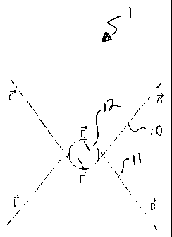
A dual-string tension dynamometer (1) utilizes two strings (10, 11) wrapped
around approximately ninety degrees of a test wheel (12). The lateral forces
(E, F) are balanced such that the total lateral force net value is zero. The
results reflect purely torsional loading.


French Abstract

L'invention concerne un dynamomètre à double corde (1) qui utilise deux cordes (10, 11) entourées sur environ 90 degrés autour d'une roue d'essai (12). Les forces latérales (E, F) sont équilibrées de sorte que la valeur nette totale des forces latérales soit nulle. Les résultats fournis par l'appareil reflètent simplement la charge de torsion.

Claims

Note: Claims are shown in the official language in which they were submitted.


CLAIMS

We claim:

1. A string tension dynamometer comprising a test wheel, a first filament
wrapped
around said test wheel and a second filament wrapped around said test wheel;
wherein said first and said second filaments are wrapped around said test
wheel
on substantially opposite sides thereof; wherein lateral forces on said first
and said
second filaments are substantially balanced such that the total lateral force
net
value is substantially zero.

2. A string dynamometer as in claim 1, wherein said first filament is wrapped
around
said test wheel to form about a 90 degree angle.

3. A string dynamometer as in claim 2, wherein said second filament is wrapped
around said test wheel to form about a 90 degree angle.

6


Description

Note: Descriptions are shown in the official language in which they were submitted.


CA 02502472 2005-04-14
WO 2004/036167 PCT/US2003/033253
DUAL-STRING DYNAMOMETER FOR MEASURING DENTAL HANDPIECE
POWER AT HIGH SPEED AND LOW TORQUE
TECHNICAL FIELD
[0001] The present invention is generally related to string tension
dynamometers used
to measure power in a high speed, low torque dental handpiece. More
particularly, the
invention relates to such a dynamometer employing dual or two strings in order
to avoid
a lateral force being exerted on the test wheel. The lateral forces are
balanced resulting in
a total lateral force net value of zero.
BACKGROUND OF THE INVENTION
[0002] The power output of high-speed, low torque dental handpieces, such as
air
turbine handpieces, can be measured using a string tension dynamometer. For
example,
it is know to use a Kerfoot string tension dynamometer, which is a device that
applies a
load to a handpiece through a string looped around a pulley mounted in a
handpiece
chuck (See FIG. 1). String tension is measured by the deflection of weighted
dials to
which the ends of the string are attached. Under steady-state conditions, the
net tension
on the string multiplied by the pulley radius is equal to the handpiece
torque.
[0003] According to one test protocol, the face of the pulley is half blacked
out for
speed detection using an optical tachometer. The pulley shaft conforms to DIN
13950 and
ISO 1797 (0.0628", 1.595 millimeters diameter). The pulley wheel is
lightweight
aluminum, unconcentricity not more the 0.0003 inches. Each pulley is tested
for balance


CA 02502472 2005-04-14
WO 2004/036167 PCT/US2003/033253
at speeds up to 500,000 RPM by recording the free spin RPM of a new handpiece
with
each pulley and discarded if they are statistical outliers. The maximum power
output of a
handpiece occurs at a speed that is about half the no-load (or free-running)
speed. To
determine the power output, the maximum speed and the torque at half the
maximum
speed is measured. Torque and power can be measured as follows:
P=vT, where v = RPM (20/60 and T=(TR - TL)mgR
P is the power in Watts.
v is the speed expressed as angular velocity, radians per second.
RPM is the speed in revolutions per minute at which the torque was measured.
~ is the constant 3.14159.
T is the torque expressed as Newton-meters.
TR and TL are the right and left dial deflection readings (See FIG. 1).
m is the mass of the dial weights expressed in kilograms.
g is the gravitational acceleration, about 9.8 meters per secondz.
R is the pulley radius in meters (such as for example, 0.100" or 2.54x10⁻³
meters). The actual pulley radius is adjusted to compensate for the thickness
of
the string. The effective pulley radius including the radius of the string is
0.100".
[0004] While such dynamometers have proven valuable in determining power, they
do
result in a small lateral force being exerted on the test wheel. Therefore, a
purely
2


CA 02502472 2005-04-14
WO 2004/036167 PCT/US2003/033253
torsional load never exists resulting in increased measurement error. A need
exists
therefore, for a string tension dynamometer which will avoid the torsional
load-induced
errors.
SUMMARY OF THE INVENTION
[0005] A dual-string tension dynamometer according to the present invention
utilizes
two strings. The lateral forces are balanced such that the total lateral force
net value is
zero. The results reflect purely torsional loading.
BRIEF DESCRIPTION OF THE DRAWINGS
[0006] FIG. 1 is a schematic representation of a Prior Art single string
tension
dynamometer, showing the left and right dial deflection readings as TL and TR
respectively. The force vector representing tension at Ts is equal to the sum
of T~ and
TR.
[0007] FIG. 2 is a schematic representation of a dual-string tension
dynamometer
according to the present invention.
PREFERRED EMBODIMENT FOR CARRYING OUT THE INVENTION
[0008] A single-string dynamometer works on the premise that the tension
difference
between two sides of a load string equals the force applied to a test wheel at
that specific
radius. By summing vectors a resultant vector is found. This resultant cannot
be zero
due to the nature of the dynamometers operation. Additionally, this vector may
include
an orthogonal component if the load string is not mounted tangent to the test
wheel.
3


CA 02502472 2005-04-14
WO 2004/036167 PCT/US2003/033253
According to the present invention, adding a second string introduces a second
set of
forces. By keeping appropriate tension magnitudes equal, a zero net force
results. A
state of purely torsional loading has been reached.
[0009] A dual-string dynamometer 1 according to the invention includes two
filaments
and 11, wrapped around approximately ninety degrees of a test wheel 12. A
conventional control device (not shown) may be introduced to maintain equal
tensions
and a zero lateral load. Power values are determined by multiplying torque
values with
angular speed data. Such relationships are expressed according to the
following
equations, where A, B, C, D, E and F are force vectors at indicated points of
the filaments
10 and 11 as shown on FIG. 2.
E=A+C
F=B+D
E+F=0
[0010] A is the tension on one end of string 10; B is the tension on a same
side of
string 11; C is the tension on the other side of string 10 from A; D is the
tension on the
other side of string 11 from B; as is shown representationally in FIG. 2.
[0011] A dual-string dynamometer 1 as described eliminates lateral loading,
which
provides loading condition certainty. High speed, low torque power data can be
accurately attained in an otherwise conventional manner.
[0012] It will be appreciated that according to the present invention, any
arrangement
using two strings could be used. String wrap angle, wheel size, and string
material can be
4


CA 02502472 2005-04-14
WO 2004/036167 PCT/US2003/033253
altered in order to accommodate testing situations. Any means of controlling
string
tension could be used with varying degrees of accuracy. Further, while such a
device is
especially useful in testing dental high speed, low torque handpieces, such a
device has
application to any number of applications. It has been described herein with
respect to
the testing of dental handpieces only for exemplary purposes and should not
necessarily
be so limited. The invention is limited only by the scope of the attached
claims.

Representative Drawing
A single figure which represents the drawing illustrating the invention.
Administrative Status

For a clearer understanding of the status of the application/patent presented on this page, the site Disclaimer , as well as the definitions for Patent , Administrative Status , Maintenance Fee  and Payment History  should be consulted.

Administrative Status

Title Date
Forecasted Issue Date 2011-05-17
(86) PCT Filing Date 2003-10-20
(87) PCT Publication Date 2004-04-29
(85) National Entry 2005-04-14
Examination Requested 2008-10-08
(45) Issued 2011-05-17
Deemed Expired 2020-10-20

Abandonment History

There is no abandonment history.

Payment History

Fee Type Anniversary Year Due Date Amount Paid Paid Date
Application Fee $400.00 2005-04-14
Maintenance Fee - Application - New Act 2 2005-10-20 $100.00 2005-10-20
Registration of a document - section 124 $100.00 2006-06-15
Maintenance Fee - Application - New Act 3 2006-10-20 $100.00 2006-07-04
Maintenance Fee - Application - New Act 4 2007-10-22 $100.00 2007-10-02
Maintenance Fee - Application - New Act 5 2008-10-20 $200.00 2008-10-01
Request for Examination $800.00 2008-10-08
Maintenance Fee - Application - New Act 6 2009-10-20 $200.00 2009-10-02
Maintenance Fee - Application - New Act 7 2010-10-20 $200.00 2010-10-01
Final Fee $300.00 2011-03-03
Maintenance Fee - Patent - New Act 8 2011-10-20 $200.00 2011-09-30
Maintenance Fee - Patent - New Act 9 2012-10-22 $200.00 2012-09-12
Maintenance Fee - Patent - New Act 10 2013-10-21 $250.00 2013-09-13
Maintenance Fee - Patent - New Act 11 2014-10-20 $250.00 2014-09-24
Maintenance Fee - Patent - New Act 12 2015-10-20 $250.00 2015-09-30
Maintenance Fee - Patent - New Act 13 2016-10-20 $250.00 2016-09-28
Maintenance Fee - Patent - New Act 14 2017-10-20 $250.00 2017-09-27
Maintenance Fee - Patent - New Act 15 2018-10-22 $450.00 2018-09-26
Maintenance Fee - Patent - New Act 16 2019-10-21 $450.00 2019-09-25
Owners on Record

Note: Records showing the ownership history in alphabetical order.

Current Owners on Record
DENTSPLY INTERNATIONAL INC.
Past Owners on Record
FANCIULLO, TODD
NOVAK, EUGENE J.
PAPANEK, TOM
PARAFINCZUK, TADEUSZ
Past Owners that do not appear in the "Owners on Record" listing will appear in other documentation within the application.
Documents

To view selected files, please enter reCAPTCHA code :


To view images, click a link in the Document Description column. To download the documents, select one or more checkboxes in the first column and then click the "Download Selected in PDF format (Zip Archive)" or the "Download Selected as Single PDF" button.

List of published and non-published patent-specific documents on the CPD .

If you have any difficulty accessing content, you can call the Client Service Centre at 1-866-997-1936 or send them an e-mail at CIPO Client Service Centre.


Document
Description 
Date
(yyyy-mm-dd) 
Number of pages   Size of Image (KB) 
Claims 2005-04-14 1 18
Abstract 2005-04-14 1 42
Drawings 2005-04-14 1 6
Description 2005-04-14 5 142
Representative Drawing 2005-07-14 1 3
Cover Page 2005-07-14 1 31
Cover Page 2011-04-18 1 31
Representative Drawing 2011-04-18 1 3
Assignment 2005-04-14 2 88
PCT 2005-04-14 5 146
Correspondence 2005-07-11 1 27
Fees 2005-10-20 1 35
Assignment 2006-06-15 4 137
Correspondence 2006-06-15 1 51
Prosecution-Amendment 2008-10-08 1 46
Correspondence 2011-03-03 2 59