Language selection

Search

Patent 2502750 Summary

Third-party information liability

Some of the information on this Web page has been provided by external sources. The Government of Canada is not responsible for the accuracy, reliability or currency of the information supplied by external sources. Users wishing to rely upon this information should consult directly with the source of the information. Content provided by external sources is not subject to official languages, privacy and accessibility requirements.

Claims and Abstract availability

Any discrepancies in the text and image of the Claims and Abstract are due to differing posting times. Text of the Claims and Abstract are posted:

  • At the time the application is open to public inspection;
  • At the time of issue of the patent (grant).
(12) Patent Application: (11) CA 2502750
(54) English Title: TOOL ROLL
(54) French Title: TAPIS DEROULABLE POUR LE RANGEMENT D'OUTILS
Status: Deemed Abandoned and Beyond the Period of Reinstatement - Pending Response to Notice of Disregarded Communication
Bibliographic Data
Abstracts

English Abstract


A tool roll constructed for removable attachment to a vertical surface to
store and display tools.
The tool roll may include loops, pockets or pouches for storing tools and tool
accessories. The
tool roll is provided with closure means, which may be combined with the
removable attachment
means.


Claims

Note: Claims are shown in the official language in which they were submitted.

Claims:
1. In a tool roll including a sheet having first and second ends to be rolled
or folded to
contain a plurality of implements and including means for fastening the roll
in the closed
position the improvement comprising;
means on said sheet for removable engagement with a vertical surface.
2. The tool roll as claimed in claim 1 wherein the means for engagement with
the vertical
surface is mechanical attachment means on a strap.
3. The tool roll as claimed in claim 2 wherein means is provided on the strap
to detachably
secure the strap to the sheet.
4. The tool roll as claimed in claim 1 wherein material is secured to the
sheet
to form loops, pockets or pouches to receive implements.
5. The tool roll as claimed in claim 2 wherein the means for engagement with
the vertical
surface comprises a plurality of straps.
6. The tool roll as claimed in claim 1 wherein the means for fastening the
tool roll in the
closed position comprises cooperating mechanical attachment means.
7. The tool roll as claimed in claim 3 wherein the means for detachably
securing the strap
to the sheet comprises mechanical attachment means.
8. The tool roll as claimed in claim 7 wherein the mechanical attachment means
for
securing the strap to the sheet cooperates with mechanical attachment means
for closing the roll.
6

Description

Note: Descriptions are shown in the official language in which they were submitted.


CA 02502750 2005-03-29
Tool Roll
Field of the Invention
This invention relates to tool rolls, more particularly to storing, displaying
and carrying tools of a
variety of sizes and shapes.
Background of the Invention
The objective of the prior art is to provide a tool roll that can store a
variety of tools and could be
quickly rolled closed for carrying or storing and opened for providing visual
and physical access
to the tools by the user. Prior art rolls could be kept in the rolled up -
closed position with the
use of ties such as US Patent No. 754,558. More recent prior art rolls may
have a single strap
having a hook pad on one end and a Velcro~ type hook receiving pad on the
outside cover to
close the roll and keep it in the rolled up position as shown in US Patent
Nos. 6,070,729 and
D476,811. In order to hold tools and keep them accessible, prior art
inventions usually have a
series of pockets attached on both side edges of the roll, as shown in US
Patent No. 1,094,009,
and in some cases, pockets are only present on one side edge as in US Patent
No. D476,811.
In US Patent No. 4,682,691 the user has to accommodate for the different
lengths of the two
piece pressure adhesive tool retaining material as the hook receiving strip,
which is permanently
attached to the inside surface of the tool roll is one length while the hook
strip is a different,
longer length as it has to go around a substantial part of the tool's
circumference in order to
snuggly retain the tool on the hook strip.
Prior art tool rolls can be permanently attached to a vertical surface with
nails or screws. Once
the tool roll is permanently attached to a wall, the user cannot remove it
quickly and
conveniently and without using another tool for assistance. Other tool rolls
hang on a clothes
hanger type hook which may be suspended on a nail or hook in a wall. When the
tool roll hangs
on a single clothes hanger type hook, the roll becomes unstable as it swings
when the user
attempts to remove or place a tool.
2

CA 02502750 2005-03-29
Summary of the Invention
An improved tool holder of this invention includes a sheet of material having
first and second
surfaces, a pair of side edges and a pair of end edges, the dimension of the
sheet being such as to
allow the sheet to be rolled up or folded to surround a plurality of
implements and having
removable attachment means located on an end edge and further comprising
closure means. The
removable attachment means provides a quick and repeatable method of attaching
the tool roll to
a vertical surface. Material may be secured to the first and second surface of
said sheet in any
desired pattern, size, number and orientation to form loops, pockets or
pouches to accommodate
a variety of tools and tool accessories.
Brief description of the drawings
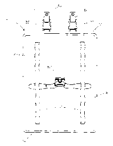
Fig. 1 is a plan view of the inside of the tool roll showing loops, buckles
and means to attach the
tool roll to a wall;
Fig. 2 is a plan view of the outside of the tool roll showing the wall
attachment means separate
from the tool roll;
Fig. 3 is a side view of the tool roll also showing a cross-sectional view of
the wall attachment
means separate from the tool roll;
Fig. 4 is a side view of the tool roll also showing a cross-sectional view of
the wall attachment
means connected to the tool roll and attached to a vertical surface;
Fig. 5 is perspective view of the tool roll in a closed position.
Detailed description of the drawings
In a preferred embodiment, the tool roll 10 may have a plurality of strips 20,
in this case, the tool
roll of Fig. 1, has a pair of strips substantially parallel to each other. The
strips 20 are attached to

CA 02502750 2005-03-29
a first surface 16 of the tool roll 10 so as to form loops 22 as shown in
Figs. 1, 3 and 4. The
strips 20 can be made of resilient, elastic materials or suitable non-
resilient materials such as
woven nylon mesh or strapping. The loops 22 can be formed by sewing or gluing
strips 20 to the
first surface 16 in any desired arrangement to store tools such as a
spokeshave 50, as shown in
Fig. 1.
The tool roll 10 shown in Fig. 4 is in an open position hanging on screws 40.
The tool roll 10
has a pair of identical straps 36 and 37 on a second surface 18 as shown in
Fig. 2. In the present
embodiment, an eyelet 38 can be an aperture in straps 36 and 37 reinforced by
stitching or by
application of a grommet 39 as shown in Fig. 2. The eyelet 38 containing first
ends 52 and 56 of
the straps 36 and 37 may be permanently attached to a vertical surface with
the screws 40 as
shown in Fig. 1.
The straps 36 and 3? can be made of any suitable, non-resilient material such
as woven nylon
mesh. Buckles 30 are provided on the straps 36 and 37. The first end 52 of the
strap 36 has a
female buckle member 32 shown in Fig. 2. Second end 54 of the strap 36 has a
male buckle
member 34 to be positioned in the female buckle member 32. Similarly, the
first end 56 of the
strap 37 has a female buckle member 33 shown in Fig. 2. Second end 58 of the
strap 37 has a
male buckle member 34 to be positioned in the female buckle member 33.
In use, the tool roll 10 may be suspended on the screws 40 through the eyelets
38 located on the
first ends 52 and 56 of the straps 36 and 37. In order to detach the tool roll
10 from the wall, the
buckles 30 may be separated. The first end 52 of the strap 36 and the first
end 56 of the strap 37
may be left permanently on the screws 40 fastened on a vertical surface. Once
the buckles 30 are
separated, the tool roll I O can be conveniently rolled up or folded. In order
to close the tool roll
for transporting or storing tools, the male buckle members 34 and a second set
of female
buckle members 35, located on the second surface 18 of the tool roll 10 are
coupled to prevent
the tool roll from opening. The tool roll 10 is shown in a closed position in
Fig. 5.
In an alternative embodiment, the surfaces 16 and 18 of tool roll 10 may have
pouches, pockets
and compartments for convenient storage of auxiliary tool parts or tool
accessories, not shown.
4

CA 02502750 2005-03-29
In an alternative embodiment, the straps 36 and 37 may be provided with
fasteners and the
second surface 18 may be provided with corresponding fastener receivers to
keep the tool roll 10
in a closed position. The tool roll 10 may be furnished with a handle for
convenient
transportation.
To open and re-attach the tool roll 10 to the vertical surface, the user will
separate the male
buckle members 34 from the female buckle members 35 located on the straps 36
and 37, unroll
or unfold the tool roll 10 and conveniently couple the male buckle members 34
to the female
buckle members 32 and 33 located on the first ends 52 and 56 on the straps 36
and 37 which are
permanently secured to the vertical surface with the screws 40.
S

Representative Drawing
A single figure which represents the drawing illustrating the invention.
Administrative Status

2024-08-01:As part of the Next Generation Patents (NGP) transition, the Canadian Patents Database (CPD) now contains a more detailed Event History, which replicates the Event Log of our new back-office solution.

Please note that "Inactive:" events refers to events no longer in use in our new back-office solution.

For a clearer understanding of the status of the application/patent presented on this page, the site Disclaimer , as well as the definitions for Patent , Event History , Maintenance Fee  and Payment History  should be consulted.

Event History

Description Date
Inactive: Office letter 2014-09-08
Revocation of Agent Requirements Determined Compliant 2014-09-08
Appointment of Agent Requirements Determined Compliant 2014-09-08
Appointment of Agent Request 2014-08-15
Revocation of Agent Request 2014-08-15
Application Not Reinstated by Deadline 2011-03-29
Time Limit for Reversal Expired 2011-03-29
Deemed Abandoned - Failure to Respond to Maintenance Fee Notice 2010-03-29
Inactive: Abandon-RFE+Late fee unpaid-Correspondence sent 2010-03-29
Application Published (Open to Public Inspection) 2006-09-29
Inactive: Cover page published 2006-09-28
Letter Sent 2005-06-28
Inactive: Single transfer 2005-06-03
Inactive: IPC assigned 2005-05-30
Inactive: First IPC assigned 2005-05-30
Inactive: Filing certificate - No RFE (English) 2005-05-05
Filing Requirements Determined Compliant 2005-05-05
Inactive: Courtesy letter - Evidence 2005-05-05
Application Received - Regular National 2005-05-05

Abandonment History

Abandonment Date Reason Reinstatement Date
2010-03-29

Maintenance Fee

The last payment was received on 2009-03-24

Note : If the full payment has not been received on or before the date indicated, a further fee may be required which may be one of the following

  • the reinstatement fee;
  • the late payment fee; or
  • additional fee to reverse deemed expiry.

Please refer to the CIPO Patent Fees web page to see all current fee amounts.

Fee History

Fee Type Anniversary Year Due Date Paid Date
Registration of a document 2005-03-29
Application fee - standard 2005-03-29
MF (application, 2nd anniv.) - standard 02 2007-03-29 2007-02-28
MF (application, 3rd anniv.) - standard 03 2008-03-31 2008-03-19
MF (application, 4th anniv.) - standard 04 2009-03-30 2009-03-24
Owners on Record

Note: Records showing the ownership history in alphabetical order.

Current Owners on Record
LEE VALLEY TOOLS LTD.
Past Owners on Record
ROBIN C. LEE
Past Owners that do not appear in the "Owners on Record" listing will appear in other documentation within the application.
Documents

To view selected files, please enter reCAPTCHA code :


To view images, click a link in the Document Description column. To download the documents, select one or more checkboxes in the first column and then click the "Download Selected in PDF format (Zip Archive)" or the "Download Selected as Single PDF" button.

List of published and non-published patent-specific documents on the CPD .

If you have any difficulty accessing content, you can call the Client Service Centre at 1-866-997-1936 or send them an e-mail at CIPO Client Service Centre.


Document
Description 
Date
(yyyy-mm-dd) 
Number of pages   Size of Image (KB) 
Description 2005-03-29 4 162
Abstract 2005-03-29 1 10
Claims 2005-03-29 1 33
Drawings 2005-03-29 5 62
Representative drawing 2006-09-06 1 6
Cover Page 2006-09-19 1 27
Filing Certificate (English) 2005-05-05 1 157
Courtesy - Certificate of registration (related document(s)) 2005-06-28 1 114
Reminder of maintenance fee due 2006-11-30 1 112
Reminder - Request for Examination 2009-12-01 1 117
Courtesy - Abandonment Letter (Maintenance Fee) 2010-05-25 1 173
Courtesy - Abandonment Letter (Request for Examination) 2010-07-05 1 164
Correspondence 2005-05-05 1 24
Fees 2007-02-28 1 26
Fees 2008-03-19 1 26
Fees 2009-03-24 1 32
Correspondence 2014-09-08 2 116
Correspondence 2014-09-08 2 156