Note: Descriptions are shown in the official language in which they were submitted.
CA 02502929 2005-01-10
Filter Cartridge
Description
The invention relates to a filter cartridge which comprises a cartridge
container
with a filter material, with a bottom wall and a peripheral wall, and with a
lid,
which durably shuts the cartridge container, which has a lid bottom and a
strip-
shaped lateral wall along its perimeter, which is firmly fixed on the Inner
side of
the cartridge container.
Filter cartridges are components of filter devices, in particular of water
filters, and
are inserted as replaceable components in pressure-proof outer containers. The
outer contour of the filter cartridge corresponds essentially to the Inner
contour of
the outer container, so that it withstands the pressure acting on the
cartridge wall
due to the fluid to be filtered. Therefore, the bottom wall and the peripheral
wall
of the filter cartridge need not have a design that is stable under pressure.
However, the situation is different with the cartridge lid, because, in
general,
there is recess between the cartridge lid and the lid of the outer container.
This
recess results possibly due to the circumstance that the lid is inserted in
the
cartridge container and is fixed at the inner side of the wall of the
cartridge
container, whereby the encircling lateral wall of the cartridge lid protrudes
upward against the bottom wall of the cartridge container. This kind of
embodiment of the cartridge lid requires not only a design that is stable
under
the action of pressure on the lid, but also a fastening of the lid on the
cartridge
container that is stable against the action of pressure, so as to prevent
leakages.
The lid bottom forms almost a right angle, projecting upward, with the lateral
wall
that is built along its periphery, as, for example, it is described in DE 199
58
649.7. Due to the internal pressure, the upward oriented forces act on the lid
bottom, which bulges upward and is stretched as its result. This leads to the
consequence that, on the lateral wall, in the region connected with the lid
bottom,
-1-
CA 02502929 2005-01-10
radial, Inward oriented, forces act, which leads to the loosening of the
lateral wall
and to formation of cracks in the connecting region.
The large number of pressure Impacts, which act upon the cartridge and the
cartridge lid In course of the operation of the filter device, can lead to
leakages in
long term, necessitating complete replacement of the filter cartridge as a
whole.
At present a solution that can solve this problem does not exist.
In the utility model DE 297 15 504 U1, a casing for the air purifier element
is
known, which is supposed to ensure sufficient stability under variable
pressure
conditions. Insofar as the current status of the technology is concerned, an
air
filter housing Is mentioned In that prior printed publication, In which the
upper
part has a bulge oriented outwards. In contrast to that, in this document, it
is
proposed that the bulge be oriented Inwards, so that the air pulsations, which
result from pressure fluctuations, are dampened due to the relatively firm
border
region. How this lid part is fixed in the casing, or whether it is an integral
part of
the casing, is not reported.
In EP 0 861 682 B1, a lid for filter casing Is described which shows less
suction
effect when the filter casing is taken off and lets In less air into the
interior of the
filter casing when it is put on. The aforesaid lid Is a removable lid, which,
as the
whole, has a slightly bulging bottom, without curved edge section, and it has
mantle-shaped lateral wall along its perimeter, which has a matching form
according to the periphery and extends in the direction of Its longitudinal
axis on
both sides of the bottom and gives the lid the form of a bowl that is open
below.
On its lower side, external screw threads are provided on Its lateral wall,
which,
acting in combination with the corresponding internal screw threads of the
filter
housing, form the means for fastening, so that the lid is therewith fixed on
the
casing. Above the external screw threads in the outer side of the lateral
wall, an
encircling snap ring groove is provided in which an O-ring is arranged as a
-2-
CA 02502929 2005-01-10
medium for sealing. Further, at one point on the lid below the snap ring
groove,
there is an opening running radially along the longitudinal axis crosswise,
through which the inner sides of the bowl-shaped lid are interconnected with
its
outside.
This lid is fabricated from a relatively thick-walled material whereby the
bottom of
the lid bulges slightly outward as a whole, so as to give the lid adequate
stability
if the filter housing is exposed to overpressure in course of its operation.
Since
the lateral wall of the lid is connected with the container wall only through
the
external screw threads anyway, a certain elasticity of the lateral wall is
ensured,
which does not lead to leakages due to the additional sealing at the upper
section of the lateral wall.
US 5,830,348 describes a fuel filter and a pressure controller which are
arranged
in a joint housing with peripheral wall. The housing is provided with a lid
with an
outlet connection for the fuel. The base of the lid comprises curvatures,
which in
the direction of the peripheral wall change into an inward curved section of
the
edge which changes into a section of the sidewall affixed to the housing via
another outside curved section.
The task of the present invention is to prolong the service life of the filter
cartridge with durably fastened lids.
This task is solved with a filter cartridge, which is characterized in that
the lid
bottom merges with the lateral wall in the direction of the peripheral wall
along a
curved edge section, in which the curved edge section and the stripe-shaped
lateral wall join in the area with matching form in a common, pointed, inward-
oriented wall section.
The invention is based on the knowledge that the forces Fo acting on the lid
bottom due to the internal pressure result in a tensile force FZ acting in the
area
-3-
CA 02502929 2005-01-10
of the common wall section, which has, due to the curvature of the edge
section,
a major force component parallel to the lateral wall and, at the best only a
small,
inward oriented, force component perpendicular to the lateral wall. This means
that the area of the lateral wall fastened with the peripheral wall is also
exposed
to tension only along the lateral wall and the peripheral wall, as a result of
which
the danger of a shear fracture is minimized at the lower end of the fastening
area.
-3a-
CA 02502929 2005-01-10
Another advantage of the curved edge section is that the forces acting on the
lid
due to the internal pressure can not only be weakened in the edge area, but
can
also be used for generating a sealing force. Due to the fact that the lateral
wall
and the curved edge section of the lid bottom form a common wall section in
the
interior of the filter cartridge, the force component F, acting due to the
Internal
pressure on the common wall section, is radially outward oriented so that the
common wall section is pressed against the peripheral wall of the cartridge
container. Thereby, it Is of advantage If the common wall section forms the
lower
wall section of the lateral wall.
On the whole, the load Is clearly reduced In the critical area of the
peripheral wall
at the lower end of the fastening area, so that the leakages are effectively
prevented in that area and the service life of the filter cartridge is limited
mainly
due to the consumption of the filter material.
Preferably, the lateral wall connects with the curved edge section
tangentially.
Preferably, the lateral wall has a form matching with that of the curved edge
section.
The inward oriented force component of the tensile force, which acts on the
lateral wall and on the peripheral wall, is reduced further due to the
tangential
orientation. In the outer side of the lid, a wedge-shaped ring space Is built
In the
edge area. It was found that it Is enough, if the curved wall section extends
up to
the Inner end of the stripe-shaped lateral wall.
it was also found that greater the radius of curvature of the curved edge
section,
more favorable is the force distribution, whereby the upper limit is given by
the
dimensions of the cartridge container. Preferably, the curved edge section has
a
mean radius of curvature R, which satisfies Rz3xS, in particular Rz5xS,
whereby
S denotes the thickness of the wall of the peripheral wall.
-4-
CA 02502929 2005-01-10
Preferably the curved edge section has an angle a between 80 and 100 . a
Indicates the angle which spans the curvature radius R. The curved edge
section
has an essentially vertical section at one end in the area of the common wall
section and merges into an essentially horizontal lid bottom section at the
other
end. The range of the angle a from 80 to 100 takes Into account the
inclination
of the peripheral wall with respect to the bottom wall of the cartridge
container. If
the cartridge container is extended conically upward for instance, which
represents a more preferable version as such, the angle a Ilea then preferably
in
the range of 90 to 100 .
In an advantageous embodiment, the lateral wall has an upper wall section,
which extends from the common wall section upward at least up to the height of
the lid bottom. On one hand, the area of support of the stripe-shaped lateral
wall
is Increased by it, and, on the other hand, an area of support for a back-up
ring,
which can be mounted on the lid, is created. In addition, this upper wall
section
serves the purpose of enabling gripping and holding the lid by means of a
gripping tool, while inserting the cartridge and fitting it on the cartridge
wall.
By providing a back-up ring, which is arranged between the cartridge lid and
the
lid of the outside container, the cartridge lid can be designed with a thinner
wall,
because the pressure exerted on the inside of the cartridge lid is practically
transmitted through the back-up ring to the lid of the outside container.
Since the
back-up ring is reusable, but the lid as well as the filter cartridge must be
disposed of later as wastes, costs for the lid material can thus be saved.
Preferably the bottom contour of the back-up ring is built essentially with a
form
complementary to the outside contour of the lid, so that the lid can help
support
the back-up ring when exposed to compressive stress.
-5-
CA 02502929 2005-01-10
In pressureless condition, the back-up ring does not completely fill the wedge-
shaped ring area. It is of advantage, if there Is a slit-shaped recess between
the
back-up ring and at least one section of the curved edge section adjacent to
the
common wall section. This slit-shaped recess can extend up to the horizontal
end of the curved edge section. Thus the idea of the essentially complementary
form is to be understood taking into account this slit shaped recess.
Providing such a recess is of advantage, because otherwise the outside area of
the rid would be subject to friction on the lower side of the back-up ring
when
exposed to the pressure impacts and hence would damage the lid in the long
run. In the edge area of the lid, that is, In the wedge-shaped ring area, this
would
lead to a disadvantageous notch effect. Due to the large pressures, the lid
material can reach the zone of the yielding point. Thus, this recess is
provided so
that in the case of plastic deformation, a portion can be pushed into this
recess.
This means that the support to the full area of the lower side of the lid can
be
provided only if it is exposed to extreme pressure.
The lid can be joined with the peripheral wall of the cartridge container, for
example, by means of adhesive bonding or welding. Preferably, however, laser
welding is used, because with that the desired section of the lateral wall can
be
welded with the peripheral wall with greater precision. Thereby, at least one
section of the common wall section is laser welded with the peripheral wall of
the
cartridge container. It was found that the entire width of the lateral wall
need not
be welded with the peripheral wall of the cartridge container in order to
achieve
adequate stability. It is advantageous if the welded area extends up to the
lower
end of the common wall section.
To enable laser welding, the material of the cartridge container is
transparent to
the laser light and the material of the lateral wall of the lid is absorptive
to the
laser light. Thereby it is adequate if the material of the lateral wall in the
cartridge
lid only is absorptive to the laser light.
-6-
CA 02502929 2005-01-10
Exemplary embodiments of the invention are explained in detail with the help
of
the following Figures.
Figures shown are:
Fig. I A section of a filter cartridge in perspective view,
Fig. 2a, b Magnified views of the detail X,
Fig. 3 A section of the upper area of the fitter cartridge with a backup
ring, and
Fig. 4 A magnified view of the detail Y in Fig. 3.
In Fig. 1, a vertical section view of a filter cartridge I is shown with a
cartridge
container 6, bottom wall 2, peripheral wall 3 and opening border 4. The filter
material within the filter cartridge Is not shown. The peripheral wall 3 is
designed
conically in this embodiment. A cylindrical peripheral wall is also possible.
In the interior of the cartridge container, the cartridge lid 10 is inserted
with
clearance to the opening border 4. The cartridge lid 10 has a lid bottom 11,
which has, except for the central area, essentially a horizontal middle part
12
and a curved edge section 14, for which further explanation is given in
connection with Figs. 2a, b.
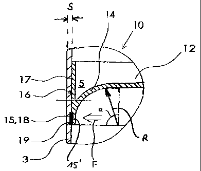
in Fig. 2a, the detail X is shown with magnification. It can be seen that the
horizontal middle part 12 merges in the direction of the peripheral wall 3
with the
curved edge section 14, which extends into the interior of the filter
cartridge and
joins its vertical section 15' with the lateral wall 16 in the common wail
section
15. The strip-shaped lateral wall 16 has an upper lateral wall section 17 and
a
-7-
CA 02502929 2005-01-10
lower lateral wall section 18, whereby the lower lateral wall section 18 is
identical
with the common wall section 15. This common wall section 15 tapers downward
to a pointed tip.
The curved wall section 14 it Is so strongly curved that it turns up to the
vertical
direction, that is the lateral wall 16 is shaped tangentially along the curved
edge
section 14. The lateral wall 16 extends almost parallel to the peripheral wall
3.
The curved edge section 14 is characterized by the curvature radius R, which,
in
the example shown here, amounts to approximately 7xS, whereby S indicates
the thickness of the wall of the peripheral wall 3. The angle q indicates the
region
spanned by the radius of curvature R, whereby R can also be the mean radius of
curvature. The curved edge section 14 is spanned by the angle a of
approximately 90 .
The peripheral wall 3 can be built with conical form and forms an obtuse angle
with the bottom wall (not shown here).
The upper wall section 17 extends upward across the horizontal middle part 12,
whereby a ring area 5 with a wedge-shaped cross section Is formed between the
upper lateral wall section 17 and the curved edge section 14. The wedge-shaped
ring area 5 is spanned by an acute angle, preferably of 40 - 50
The common well section 15 is welded, in particular laser welded, with the
peripheral wall 3 in the area 19. The diameter of the lid is preferably
fabricated
with excess dimensions, so that the wall section 15 is further pressed against
the
peripheral wall 3 during the welding. This initial compression is especially
advantageous in the laser welding for achieving a homogeneous weld. This area
19 extends upward from the lower tip of the common wall section 15, whereby it
is sufficient that this welded area 19 does not span the entire width of the
lower
lateral wall section 18.
-8-
CA 02502929 2005-01-10
The force generated by the internal pressure is denoted, for example, by arrow
F. it can be seen that the Inside pressure presses on the common wall section
15 and thus exerts an additional sealing force, especially in the weld section
19.
Fig. 2b corresponds to Fig. 2a, whereby additionally, the lid, bulged by the
force
Fa acting on the Inside, is shown with broken lines. The middle part 12 and
the
curved edge section 14 are pressed upward and assume the positions 12', 14',
which lead to the tensile forces Fz, who have their main component FZH in the
common wall section 15 parallel to the lateral wall 16. Due to this, only a
small,
inward oriented force acts on the welded section 19, which reduces the risk of
shear fracture under the action of pressure Impacts In the predamaged critical
area of the peripheral wall 3 at the lower ends of the welding joints.
In Fig. 3, the filter cartridge with the back-up ring 20 described In the
Figs.1 and
2 is shown. The complete lid 10 is shown In the drawing and has a connecting
tube 13 at the center. Accordingly, the back-up ring 20 also has a ring
opening
27 at its center, so that these connecting tubes 13 are freely accessible from
above.
The back-up ring 20 has radial reinforcing ribs 21, which are connected with
each other by a common back-up ring bottom 22 in the lower area and with a
common back-up ring wall 26 in the outside border area. The contour of the
back-up ring bottom 22 has a design almost complementary to the outside
contour of the lid 10, whereby the lateral wail 26 of the back-up ring 20 fits
closely with the lateral wail 16.
A magnified view of the detail Y is shown in Fig. 4. A slit-shaped ring area
30 is
formed in the area of the wedge-shaped ring area above the curved edge
section 14, especially above the section 14" of the curved edge section 14 of
the
lid 10. The lower section 14' of the curved edge section 14 borders the common
-9-
CA 02502929 2005-01-10
wall section 15. This is achieved, by means of the layout, such that the tip
border 25 of the tapering curved bottom section 24 of the back-up ring bottom
22
does not extend completely up to the ring area 5 and the curved section 24 of
the back-up ring bottom 22 has a lesser radius of curvature compared to the
curved edge section 14. This different radius of curvature leads to it that in
the
horizontal section 23 of the back-up ring bottom 22, it fits closely at the
horizontal
middle part 12 of the lid bottom.
-10-
CA 02502929 2005-01-10
Reference Symbols
I Filter Cartridge
2 Bottom Wall
3 Peripheral Wall
4 Opening Border
5 Wedge-shaped Ring Area
6 Cartridge Container
Lid
10 11 Lid Bottom
12 Horizontal Middle Part
12' Horizontal Middle Part
13 Connecting Pipe
14 Curved Edge Section
14' 14' Lower Section
14" 14" Upper Section
15 Common Wall Section
15' Vertical Section
16 Lateral Wall
17 Upper Lateral Wall Section
18 Lower Lateral Wall Section
19 Welded Section
20 Back-up Ring
21 Radial Reinforcement Rib
22 Back-up Ring Bottom
23 Horizontal Section
24 Curved Section
25 Tip Border
26 Back-up Ring Wall
27 Ring Opening
30 Slit-shaped Recess
-11-