Note: Descriptions are shown in the official language in which they were submitted.
CA 02502978 2008-01-07
TITLE: HIGH-STRENGTH SURFACE-MOUNTED ANCHORS AND
WALL ANCHOR SYSTEMS USING THE SAME
BACKGROUND OF THE INVENTION
1. Field of the Invention
[002] This invention relates to high-strength wall anchors and to
surface-mounted anchoring systems employing the same, both of which
are used in cavity wall constructs. More particularly, the
invention relates to sheetmetal wall anchors and wire formative
veneer ties that comprise positive interlocking components of the
anchoring system. The system has application to seismic-resistant
structures and to cavity walls having special requirements. The
latter include high-strength requirements for both insulated and
non-insulated cavities, namely, a structural performance
characteristic capable of withstanding a 100 lbf, in both tension
and compression.
Page 1
CA 02502978 2005-03-30
2. Description of the Prior Art
[003] In the late 1980's, surface-mounted wall anchors were
developed by Hohmann & Barnard, Inc., and patented under U.S.
Patent 4,598,518 of the first-named inventor hereof. The invention
was commercialized under trademarks DW-10, DW-10-X, and DW-10-HS.
These widely accepted building specialty products were designed
primarily for dry-wall construction, but were also used with
masonry backup walls. For seismic applications, it was common
practice to use these wall anchors as part of the DW-10 Seismiclip
interlock system which added a Byna-Tie wire formative, a
Seismiclip snap-in device - described in U.S. Patent 4,875,319
('319), and a continuous wire reinforcement.
[004] In an insulated dry wall application, the surface-mounted
wall anchor of the above-described system has pronged legs that
pierce the insulation and the wallboard and rest against the metal
stud to provide mechanical stability in a four-point landing
arrangement. The vertical slot of the wall anchor enables the mason
to have the wire tie adjustably positioned along a pathway of up to
3.625-inch (max.). The interlock system served well and received
high scores in testing and engineering evaluations which examined
effects of various forces, particularly lateral forces, upon brick
veneer masonry construction. However, under certain conditions, the
system did not sufficiently maintain the integrity of the
insulation. Also, upon the promulgation of more rigorous
specifications by which tension and compression characteristics
Page 2
CA 02502978 2005-03-30
were raised, a different structure - such as one of those described
in detail below - was required.
[005] The engineering evaluations further described the advantages
of having a continuous wire embedded in the mortar joint of
anchored veneer wythes. The seismic aspects of these investigations
were reported in the inventor's '319 patent. Besides earthquake
protection, the failure of several high-rise buildings to withstand
wind and other lateral forces resulted in the incorporation of a
continuous wire reinforcement requirement in the Uniform Building
Code provisions. The use of a continuous wire in masonry veneer
walls has also been found to provide protection against problems
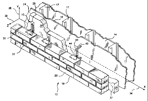
arising from thermal expansion and contraction and to improve the
uniformity of the distribution of lateral forces in the structure.
[006] Shortly after the introduction of the pronged wall anchor, a
seismic veneer anchor, which incorporated an L-shaped backplate,
was introduced. This was formed from either 12- or 14-gauge
sheetmetal and provided horizontally disposed openings in the arms
thereof for pintle legs of the veneer anchor. In general, the
pintle-receiving sheetmetal version of the Seismiclip interlock
system served well, but in addition to the insulation integrity
problem, installations were hampered by mortar buildup interfering
with pintle leg insertion.
[007] In the 1980's, an anchor for masonry veneer walls was
developed and described in U.S. Patent 4,764,069 by Reinwall et
al., which patent is an improvement of the masonry veneer anchor of
Page 3
CA 02502978 2005-03-30
Lopez, U.S. Patent 4,473,984. Here the anchors are keyed to
elements that are installed using power-rotated drivers to deposit
a mounting stud in a cementitious or masonry backup wall. Fittings
are then attached to the stud which include an elongated eye and a
wire tie therethrough for deposition in a bed joint of the outer
wythe. It is instructive to note that pin-point loading - that is
forces concentrated at substantially a single point - developed
from this design configuration. This resulted, upon experiencing
lateral forces over time, in the loosening of the stud.
[008] Exemplary of the public sector building specification is that
of the Energy Code Requirement, Boston, Massachusetts (see Chapter
13 of 780 CMR, Seventh Edition). This Code sets forth insulation R-
values well in excess of prior editions and evokes an engineering
response opting for thicker insulation and correspondingly larger
cavities. Here, the emphasis is upon creating a building envelope
that is designed and constructed with a continuous air barrier to
control air leakage into or out of conditioned space adjacent the
inner wythe.
[009] As insulation became thicker, the tearing of insulation
during installation of the pronged DW-10X wall anchor, see supra,
became more prevalent. This occurred as the installer would fully
insert one side of the wall anchor before seating the other side.
The tearing would occur at two times, namely, during the arcuate
path of the insertion of the second leg and separately upon
installation of the attaching hardware. The gapping caused in the
Page 4
CA 02502978 2005-03-30
insulation permitted air and moisture to infiltrate through the
insulation along the pathway formed by the tear. While the gapping
was largely resolved by placing a self-sealing, dual-barrier
polymeric membrane at the site of the legs and the mounting
hardware, with increasing thickness in insulation, this patchwork
became less desirable. The improvements hereinbelow in surface
mounted wall anchors look toward greater insulation integrity and
less reliance on a patch.
[010] Another prior art development occurred shortly after that of
Reinwall/Lopez when Hatzinikolas and Pacholok of Fero Holding Ltd.
introduced their sheetmetal masonry connector for a cavity wall.
This device is described in U.S. Patents 5,392,581 and 4,869,043.
Here a sheetmetal plate connects to the side of a dry wall column
and protrudes through the insulation into the cavity. A wire tie is
threaded through a slot in the leading edge of the plate capturing
an insulative plate thereunder and extending into a bed joint of
the veneer. The underlying sheetmetal plate is highly thermally
conductive, and the '581 patent describes lowering the thermal
conductivity by foraminously structuring the plate. However, as
there is no thermal break, a concomitant loss of the insulative
integrity results.
[011] In recent building codes for masonry structures, a trend away
from eye and pintle structures is seen in that the newer codes
require adjustable anchors be detailed to prevent disengagement.
This has led to anchoring systems in which the open end of the
veneer tie is embedded in the corresponding bed joint of the veneer
Page 5
CA 02502978 2005-03-30
and precludes disengagement by vertical displacement.
[012] Another application for high-span anchoring systems is in the
evolving technology of self-cooling buildings. Here, the cavity
wall serves additionally as a plenum for delivering air from one
area to another. While this technology has not seen wide
application in the United States, the ability to size cavities to
match air moving requirements for naturally ventilated buildings
enable the architectural engineer to now consider cavity walls when
designing structures in this environmentally favorable form.
[013] In the past, the use of wire formatives have been limited by
the mortar layer thicknesses which, in turn are dictated either by
the new building specifications or by pre-existing conditions, e.g.
matching during renovations or additions the existing mortar layer
thickness. While arguments have been made for increasing the number
of the fine-wire anchors per unit area of the facing layer,
architects and architectural engineers have favored wire formative
anchors of sturdier wire. On the other hand, contractors find that
heavy wire anchors, with diameters approaching the mortar layer
height specification, frequently result in misalignment. This led
to the low-profile wall anchors of the inventors hereof as
described in U.S. Patent 6,279,283. However, the above-described
technology did not address the adaption thereof to surface mounted
devices.
[014] In the course of prosecution of U.S. Patent 4,598,518
(Hohmann '518) several patents, indicated by an asterisk on the
Page 6
CA 02502978 2005-03-30
tabulation below, became known to the inventors hereof and are
acknowledged hereby. Thereafter and in preparing for this
disclosure, the additional patents which became known to the
inventors are discussed further as to the significance thereof:
Patent Inventor O.C1. Issue Date
2,058,148* Hard 52/714 Oct., 1936
2,966,705* Massey 52/714 Jan., 1961
3,377,764 Storch 04/16/1968
4,021,990* Schwalberg 52/714 05/10/1977
4,305,239* Geraghty 52/713 Dec., 1981
4,373,314 Allan 02/15/1983
4,438,611* Bryant 52/410 Mar., 1984
4,473,984 Lopez 10/02/1984
4,598,518 Hohmann 07/08/1986
4,869,038 Catani 09/26/1989
4,875,319 Hohmann 10/24/1989
5,063,722 Hohmann 11/12/1991
5,392,581 Hatzinikolas et al. 02/28/1995
5,408,798 Hohmann 04/25/1995
5,456,052 Anderson et al. 10/10/1995
5,816,008 Hohmann 10/15/1998
6,209,281 Rice 04/03/2001
6,279,283 Hohmann et al. 08/28/2001
Foreign Patent Documents
279209* CH 52/714 Mar., 1952
2069024* GB 52/714 Aug., 1981
Note: Original classification provided for asterisked items only.
[015] It is noted that with some exceptions these devices are
generally descriptive of wire-to-wire anchors and wall ties and
have various cooperative functional relationships with straight
wire runs embedded in the inner and/or outer wythe.
Page 7
CA 02502978 2005-03-30
[016] U.S. 3,377,764 - D. Storch - Issued 04/16/68
Discloses a bent wire, tie-type anchor for embedment in a facing
exterior wythe engaging with a loop attached to a straight wire run
in a backup interior wythe.
[017] U.S. 4,021,990 - B. J. Schwalberg - Issued 05/10/77
Discloses a dry wall construction system for anchoring a facing
veneer to wallboard/metal stud construction with a pronged sheet-
metal anchor. Like Storch 1764, the wall tie is embedded in the
exterior wythe and is not attached to a straight wire run.
[018] U.S. 4,373,314 - J.A. Allan - Issued 02/15/83
Discloses a vertical angle iron with one leg adapted for attachment
to a stud; and the other having elongated slots to accommodate wall
ties. Insulation is applied between projecting vertical legs of
adjacent angle irons with slots being spaced away from the stud to
avoid the insulation.
[019] U.S. 4,473,984 - Lopez - Issued 10/02/84
Discloses a curtain-wall masonry anchor system wherein a wall tie
is attached to the inner wythe by a self-tapping screw to a metal
stud and to the outer wythe by embedment in a corresponding bed
joint. The stud is applied through a hole cut into the insulation.
[020] II S 4,869,038 - M. J. Catani - Issued 091/26/89
Discloses a veneer wall anchor system having in the interior wythe
a truss-type anchor, similar to Hala et al. 1226, supra, but with
horizontal sheetmetal extensions. The extensions are interlocked
with bent wire pintle-type wall ties that are embedded within the
Page 8
CA 02502978 2005-03-30
exterior wythe.
[021] U.S. 4,879,319 - R. Hohmann - Issued 10/24/89
Discloses a seismic construction system for anchoring a facing
veneer to wallboard/metal stud construction with a pronged sheet-
metal anchor. Wall tie is distinguished over that of Schwalberg
'990 and is clipped onto a straight wire run.
[022] U.S. 5,392,581 - Hatzinikolas et al. - Issued 02/28/1995
Discloses a cavity-wall anchor having a conventional tie wire for
mounting in the brick veneer and an L-shaped sheetmetal bracket for
mounting vertically between side-by-side blocks and horizontally
on atop a course of blocks. The bracket has a slit which is
vertically disposed and protrudes into the cavity. The slit
provides for a vertically adjustable anchor.
[023] U.S. 5,408,798 - Hohmann - Issued 04/25/1995
Discloses a seismic construction system for a cavity wall having a
masonry anchor, a wall tie, and a facing anchor. Sealed eye wires
extend into the cavity and wire wall ties are threaded therethrough
with the open ends thereof embedded with a Hohmann '319 (see supra)
clip in the mortar layer of the brick veneer.
[024] U.S. 5,456,052 - Anderson et al. - Issued 10/10/1995
Discloses a two-part masonry brick tie, the first part being
designed to be installed in the inner wythe and then, later when
the brick veneer is erected to be interconnected by the second
part. Both parts are constructed from sheetmetal and are arranged
on substantially the same horizontal plane.
Page 9
CA 02502978 2005-03-30
[025] U.S. 5,816,008 - Hohmann - Issued 10/15/1998
Discloses a brick veneer anchor primarily for use with a cavity
wall with a drywall inner wythe. The device combines an L-shaped
plate for mounting on the metal stud of the drywall and extending
into the cavity with a T-head bent stay. After interengagement with
the L-shaped plate the free end of the bent stay is embedded in the
corresponding bed joint of the veneer.
[026] U.S. 6,209,281 - Rice - Issued 04/03/2001
Discloses a masonry anchor having a conventional tie wire for
mounting in the brick veneer and sheetmetal bracket for mounting
on the metal-stud-supported drywall. The bracket has a slit which
is vertically disposed when the bracket is mounted on the metal
stud and, in application, protrudes through the drywall into the
cavity. The slit provides for a vertically adjustable anchor.
[0271 U.S. 6,279,283 - Hohmann et al. - Issued 08/28/2001
Discloses a low-profile wall tie primarily for use in renovation
construction where in order to match existing mortar height in the
facing wythe a compressed wall tie is embedded in the bed joint of
the brick veneer.
[028] None of the above provide the high-strength, surface-mounted
wall anchor or anchoring systems utilizing these devices of this
invention. As will become clear in reviewing the disclosure which
follows, the cavity wall structures benefit from the recent
developments described herein that lead to solving the problems of
insulation integrity, of interference from excess mortar, and of
Page 10
CA 02502978 2005-03-30
high-strength applications. In the related Application, folded wall
anchors are structured with legs that are mounted inboard to the
baseplate thereby enabling the baseplate to cover the insertion
openings. Here, further improvements in surface-mounted anchors and
systems including surface-mounted anchors are introduced.
SUMMARY
[029] In general terms, the invention disclosed hereby is a unique
surface mounted wall anchor and an anchoring system employing the
same. The wall anchor is a sheetmetal device which is described
herein as functioning with various wire formative veneer ties. In
two embodiments, enfolded legs have a projecting portion and a
nonprojecting portion. The folded construction of the wall tie
enables the junctures of the legs and the base of the wall anchor
to be located inboard from the periphery of the wall anchor. During
formation of the wall anchor, the outer surface of the
nonprojecting portion of the enfolded leg and the underside of the
base are caused to be coplanar. Upon installation, the coplanar
elements act to seal the insertion point where the legs enter into
the exterior layer of building materials on the inner wythe. This
sealing effect precludes the penetration of air, moisture, and
water vapor into the inner wythe structure. In all of the
embodiments shown, the legs are formed to fully or partially sheath
the mounting hardware of the wall anchor. The sheathing function
reduces the openings in the insulation required for installing the
wall anchor.
Page 1 l
CA 02502978 2005-03-30
[030] In the first embodiment, the folded wall anchor is adapted
from the earlier inventions of Schwalberg, U.S. Patent 4,021,990
and of Hohmann, U.S. Patent 4, 875, 319, see supra. Here it is seen
that the double folded wall anchor (with legs moved inboard) have
deeply impressed ribs alongside the bail, which creates a wall
anchor construct of superior strength. This construct is applied to
an insulated dry wall inner wythe having insulation over wallboard
cavity, and an outer wythe of brick. The channel in the projecting
portion of the legs ensheaths the exterior side of the mounting
hardware.
[031] In the third embodiment, the folded wall anchor is of the
winged variety. The wings in this embodiment are slotted and permit
continuously adjustable positioning of the veneer tie. Here it is
seen that a double folded wall anchor together with a box veneer
tie is applied to a dry wall inner wythe having interior insulation
and, thus, the wall anchor legs have only to penetrate the
wallboard layer. In the third embodiment, the wings are slotted
with a centrally disposed reinforcement bar. The folded wall anchor
is paired with a canted, low-profile veneer anchor. The folded wall
anchor is surface-mounted to a masonry block inner wythe having
insulation on the exterior surface and a brick facing. The use of
this innovative surface-mounted wall anchor in various applications
addresses the problems of insulation integrity, thermal
conductivity, and pin-point loading encountered in the previously
discussed inventions.
Page 12
CA 02502978 2008-01-07
In accordance with one embodiment there is provided a
surface-mounted anchoring system for use in the construction of a
wall having an inner wythe and an outer wythe, the outer wythe
formed from a plurality of successive courses with a bed joint
between each two adjacent courses, the inner wythe and the outer
wythe in a spaced apart relationship the one with the other
forming a cavity therebetween, the inner wythe having an exterior
layer selected from a group consisting of insulation, wallboard,
and insulation and wallboard, the surface-mounted anchoring system
comprising: a wall anchor constructed from a plate-like body
having two major faces being the mounting surface and the outer
surface, the wall anchor, in turn, comprising; a pair of legs,
each extending from the mounting surface of the plate-like body
from an inboard location thereof with the longitudinal axis of
each of the legs being substantially normal to the face and having
a channel along the axis adapted for sheathing mounting hardware,
the legs adapted for insertion at a predetermined insertion point
into the exterior layer of the inner wythe; a cover portion formed
from the mounting surface of the plate-like body, the cover
portion adapted to preclude penetration of air, moisture and water
vapor into the exterior layer; an apertured receptor portion
adjacent the outer surface of the plate-like body, the apertured
receptor portion adapted to limit displacement of the outer wythe
toward and away from the inner wythe; at least one strengthening
rib impressed in the plate-like body parallel to the apertured
receptor portion; and, a veneer tie threadedly disposed through
the apertured receptor portion of the wall anchor and adapted for
embedment in the bed joint of the outer wythe to prevent
disengagement from the anchoring system.
Page 12a
CA 02502978 2005-03-30
OBJECTS AND FEATURES OF THE INVENTION
[032] Accordingly, it is the primary object of the present
invention to provide a new and novel anchoring systems for cavity
walls, which systems are surface mountable to the backup wythe
thereof.
[033] It is another object of the present invention to provide a
new and novel wall anchor mounted on the exterior surface of the
wallboard or the insulation layer and secured to the metal stud or
standard framing member of a dry wall construction.
[034] It is yet another object of the present invention to provide
an anchoring system which is resistive to high levels of tension
and compression and, further, is detailed to prevent disengagement
under seismic or other severe environmental conditions.
[035] It is still yet another object of the present invention to
provide an anchoring system which is constructed to maintain
insulation integrity by preventing air and water penetration
thereinto.
[036] It is a feature of the present invention that the wall anchor
hereof requires fewer openings in the insulation for installation
and has a coplanar baseplate for sealing against the insertion
points in the insulation.
[037] It is another feature of the present invention that the legs
of the wall anchor hereof have only point contact with the metal
studs with substantially no resultant thermal conductivity.
Page 13
CA 02502978 2005-03-30
[038] It is yet another feature of the present invention that the
bearing area between the wall anchor and the veneer tie spreads the
forces thereacross and avoids pin-point loading.
[039] Other objects and features of the invention will become
apparent upon review of the drawing and the detailed description
which follows.
BRIEF DESCRIPTION OF THE DRAWING
[040] In the following drawing, the same parts in the various views
are afforded the same reference designators.
[041] FIG. 1 shows a first embodiment of this invention and is a
perspective view of a surface-mounted anchoring system as applied
to a cavity wall with an inner wythe of dry wall construction
having insulation disposed on the cavity-side thereof and an outer
wythe of brick;
[042] FIG. 2 is a rear perspective view showing the folded wall
anchor of the surface-mounted anchoring system of FIG. 1 for
ensheathing the exterior of the mounting hardware;
[043] FIG. 3 is a perspective view of the surface-mounted anchoring
system of FIG. 1 shown with a folded wall anchor and a veneer tie
threaded therethrough;
[044] FIG. 4 is a cross sectional view of FIG. 1 which shows the
relationship of the surface-mounted anchoring system of this
invention to the dry wall construction and to the brick outer
Page 14
CA 02502978 2005-03-30
wythe;
[045] FIG. 5 is a perspective view of a second embodiment of this
invention showing a surface-mounted anchoring system for a seismic-
resistant cavity wall and is similar to FIG. 1, but shows wall
anchors with tubular legs and a swaged veneer tie accommodating a
reinforcing bar in the bed joints of the brick outer wythe;
[046] FIG. 6 is a rear perspective view showing the surface-mounted
anchoring system having a wall anchor with tubular legs of FIG. 5;
[047] FIG. 7 is a cross sectional view of FIG. 5 which shows the
relationship of the surface-mounted wall anchor with tubular legs
and the corresponding swaged veneer tie and reinforcing bar;
[048] FIG. 8 is a perspective view of a third embodiment of this
invention showing a surface-mounted anchoring system for a cavity
wall and is similar to FIG. 1, but shows a masonry block backup
wall with a high-strength, folded wall anchor with slotted wings
and a low-profile, canted veneer tie.
[049] FIG. 9 is a rear perspective view showing the wall anchor
with ribbed slotted wings of FIG.8 having channels for ensheathing
the interior of the mounting hardware; and,
[050] FIG. 10 is a partial perspective view of FIG. 8 showing the
relationship of the wall anchor and the corresponding veneer tie.
Page 15
CA 02502978 2005-03-30
DESCRIPTION OF THE PREFERRED EMBODIMENTS
[051] Before entering into the detailed Description of the
Preferred Embodiments, several terms which will be revisited later
are defined. These terms are relevant to discussions of innovations
introduced by the improvements of this disclosure that overcome the
technical shortcoming of the prior art devices.
[052] In the embodiments described hereinbelow, the inner wythe is
provided with insulation. In the dry wall construction, this takes
the form, in the first and second embodiments of exterior
insulation disposed on the outer surface of the inner wythe. In the
third embodiment, a masonry block backup wall construction is shown
having insulation applied to the outer surface of the masonry
block. Recently, building codes have required that after the
anchoring system is installed and, prior to the inner wythe being
closed up, that an inspection be made for insulation integrity to
ensure that the insulation prevents infiltration of air and
moisture. Here the term insulation integrity is used in the same
sense as the building code in that, after the installation of the
anchoring system, there is no change or interference with the
insulative properties and concomitantly substantially no change in
the air and moisture infiltration characteristics. It is noted that
in contradistinction to the related application cited hereinabove,
these high-strength wall anchors are designed to be less invasive
into the insulation.
Page 16
CA 02502978 2005-03-30
[053] In a related sense, prior art sheetmetal anchors have formed
a conductive bridge between the wall cavity and the metal studs of
columns of the interior of the building. Here the terms thermal
conductivity and thezmal conductivity analysis are used to examine
this phenomenon and the metal-to-metal contacts across the inner
wythe.
[054] Anchoring systems for cavity walls are used to secure veneer
facings to a building and overcome tension and compression from
seismic and other forces, i.e. wind shear, etc. In the past, some
systems have experienced failure because the forces have been
concentrated at substantially a single point. Here, the term pin-
point loading refers to an anchoring system wherein forces are
concentrated at a single point.
[055] In addition to that which occurs at the facing wythe,
attention is further drawn to the construction at the exterior
surface of the inner or backup wythe. Here there are two concerns.
namely, maximizing the strength of the securement of the surface-
mounted wall anchor to the backup wall and, as previously discussed
minimizing the interference of the anchoring system with the
insulation. The first concern is addressed using appropriate
fasteners such as, for mounting to masonry block, the properly
sized concrete threaded anchors with expansion sleeves or concrete
expansion bolts and, for mounting to metal, dry-wall studs, self-
tapping screws. The latter concern is addressed by the flatness of
the base of the surface-mounted, folded anchors covering the
Page 17
CA 02502978 2005-03-30
openings formed by the legs (the profile is seen in the cross-
sectional drawings of Figures 3 and 7).
[056] In the detailed description, the veneer reinforcements and
the veneer anchors are wire formatives. The wire used in the
fabrication of veneer joint reinforcement conforms to the
requirements of ASTM Standard Specification A951-00, Table 1. For
the purpose fo this application tensile strength tests and yield
tests of veneer joint reinforcements are, where applicable, those
denominated in ASTM A-951-00 Standard Specification for Masonry
Joint Reinforcement.
[057] Referring now to Figures 1 through 4, the first embodiment
shows an anchoring system with a high-strength, surface-mounted
wall anchor. This system is suitable for recently promulgated
standards with more rigorous tension and compression
characteristics. The system discussed in detail hereinbelow, has a
high-strength, folded wall anchor and an interengaging veneer tie.
The wall anchor is surface mounted onto an externally insulated dry
wall. For the first embodiment, a cavity wall having an insulative
layer of 2.5 inches (approx.) and a total span of 3.5 inches
(approx.) is chosen as exemplary.
[058] The surface-mounted anchoring system for cavity walls is
referred to generally by the numeral 10. A cavity wall structure 12
is shown having an inner wythe or dry wall backup 14 with sheetrock
or wallboard 16 mounted on metal studs or columns 17 and an outer
wythe or facing wall 18 of brick 20 construction. Between the inner
Page 18
CA 02502978 2005-03-30
wythe 14 and the outer wythe 18, a cavity 22 is formed. The cavity
22, which has a 3. 5- inch span, has attached to the exterior surface
24 of the inner wythe 14 insulation in the form of insulating
panels 26. The insulation 26 is disposed on wallboard 16. Seams 28
between adjacent panels of insulation 26 are shown as being
substantially vertical and each in alignment with the center of a
column 17; however, horizontal insulating panels may also be used
with the anchoring system described herein.
[059] Successive bed joints 30 and 32 are substantially planar and
horizontally disposed and in accord with building standards are
0.375-inch (approx.) in height. Selective ones of bed joints 30 and
32, which are formed between courses of bricks 20, are constructed
to receive therewithin the insertion portion of the anchoring
system hereof. Being surface mounted onto the inner wythe, the
anchoring system 10 is constructed cooperatively therewith and is
configured to minimize air and moisture penetration around the wall
anchor/inner wythe juncture.
[060] For purposes of discussion, the cavity surface 24 of the
inner wythe 14 contains a horizontal line or x-axis 34 and an
intersecting vertical line or y-axis 36. A horizontal line or z-
axis 38, normal to the xy-plane, passes through the coordinate
origin formed by the intersecting x- and y-axes. A folded wall
anchor 40 is shown which has a pair of legs 42 which penetrate the
wallboard 16 and insulation 26. Folded wall anchor 40 is a stamped
metal construct which is constructed for surface mounting on inner
wythe 14 and for interconnection with veneer tie 44.
Page 19
CA 02502978 2008-01-07
[061] The veneer tie 44 is a wire formative of a gage close to
the receptor opening measured in an xz plane. The veneer tie 44
is shown in Fig. 1 as being emplaced on a course of bricks 20 in
preparation for embedment in the mortar of bed joint 30. In this
embodiment, the system includes a wall anchor 40 and a veneer tie
44.
[062] At intervals along a horizontal line on surface 24, the
folded wall anchors 40 are surface-mounted. In this structure,
channels 47 sheathe the exterior of mounting hardware 48. The
folded wall anchors 40 are positioned on surface 24 so that the
longitudinal axis of a column 17 lies within the yz-plane formed
by the longitudinal axes 50 and 52 of upper leg 54 and lower leg
56, respectively. The legs 54 and 56 are folded, as best shown in
FIG. 2, so that the base surface of the leg portions and the base
surface of the bail portion 62 are substantially coplanar and,
when installed, lie in an xy-plane. Upon insertion in insulation
26, the base surfaces rest snugly against the opening formed
thereby and serve to cover the opening precluding the passage of
air and moisture therethrough. This construct maintains the
insulation integrity.
[063] The dimensional relationship between wall anchor 40 and
veneer tie 44 limits the axial movement of the construct. Each
veneer tie 44 has a rear leg 64 opposite the bed-joint-deposited
portion thereof which is formed continuous therewith. The slot or
bail aperture 66 of bail 62 is constructed, in accordance with the
building code requirements, to be within the predetermined
dimensions to limit the z-axis 38 movement. The slot 66 is
slightly larger horizontally than the diameter of the tie. The
receptor opening or bail slot 66 is elongated vertically to accept
a veneer tie threadedly therethrough and permit y-axis adjustment.
The dimensional relationship of the rear leg 64 to the width of
bail 62 limits the x-axis movement of the construct. For positive
Page 20
CA 02502978 2008-01-07
interengagement and to prevent disengagement under seismic
conditions, the front legs 68 and 70 of veneer tie 44 and the
reinforcement wire 46 are sealed in bed joint 30 forming a closed
loop.
[064] The folded wall anchor 40 is seen in more detail in FIGS.
2 through 4. The legs 54 and 56 are folded 180 about end seams
72 and 74, respectively, and then 90 at the inboard seams 76 and
78, respectively, so as to extend parallel the one to the other.
The legs 54 and 56 are dimensioned so that, upon installation,
they extend through insulation panels 26 and wallboard 16 and the
endpoints 80 thereof abut the metal studs 17. Although only two-
leg structures are shown, it is within the contemplation of this
invention that more folded legs could be constructed with each leg
terminating at an inboard seam and having the insertion point of
the insulation 26 covered by the wall anchor body. Because the
legs 54 and 56 abut the studs 17 only at endpoints 80, the thermal
conductivity across the construct is minimal as the cross
sectional metal-to-metal contact area is minimized. (There is
virtually no heat transfer across the mounting hardware 48 because
of the isolating, nonconductive washers thereof.)
[065] In this embodiment, as best seen in FIGS. 3 and 4,
strengthening ribs may be impressed in the base of wall anchor 40.
The ribs are substantially parallel to the bail aperture 66 and,
when mounting hardware 48 is fully seated so that the base surface
rests against the face of insulation 26, the ribs are then pressed
into the surface of the insulation 26. This provides additional
sealing. While the ribs may be protruding toward the insulation,
it is within the contemplation of this invention that ribs could
be raised in the opposite direction. The alternative structure
would be used in applications wherein the outer layer of the inner
wythe is noncompressible and does not conform to the rib contour.
The ribs strengthen the wall anchor 40 and achieve an anchor with
Page 21
CA 02502978 2008-01-07
a tension and compression rating of 100 lbf.
[066] The description which follows is a second embodiment of the
surface-mounted anchoring system for cavity walls of this
invention. For ease of comprehension, wherever possible similar
parts use reference designators 100 units higher than those above.
Thus, the veneer tie 144 of the second embodiment is analogous to
the veneer tie 44 of the first embodiment. Referring now to FIGS.
through 7, the second embodiment of the surface-mounted
anchoring system is shown and is referred to generally by the
numeral 110. As in the first embodiment, a wall structure 112 is
shown. The second embodiment has an inner wythe or backup wall
114 of a dry wall or a wallboard construct 116 on columns or studs
117 and an outer wythe or veneer 118 of facing brick 120. The
inner wythe 114 and the outer wythe 118 have a cavity 122
therebetween. Here, the anchoring system has a surface-mounted
wall anchor with tubular legs and a swaged veneer tie for
receiving reinforcement bars to create a seismic anchoring system.
[067] The anchoring system 110 is surface mounted to the exterior
surface 124 of the inner wythe 114. In this embodiment like the
previous one, panels of insulation 126 are disposed on wallboard
116 and, in turn, on columns 117. Successive bed joints 130 and
132 are substantially planar and horizontally disposed and in
accord with building standards are 0.375-inch (approx.) in height.
Selective ones of bed joints 130 and 132, which are formed between
courses of bricks 120, are constructed to receive therewithin the
insertion portion of the anchoring system construct hereof. Being
surface mounted onto the inner wythe, the anchoring system 110 is
constructed cooperatively therewith, and as described in greater
detail below, is configured to penetrate through the wallboard at
a covered insertion point.
[068] For purposes of discussion, the exterior surface 124 of the
inner wythe 114 contains a horizontal line or x-axis 134 and an
Page 22
CA 02502978 2008-01-07
intersecting vertical line or y-axis 136. A horizontal line or
z-axis 138, normal to the xy-plane, passes through the coordinate
origin formed by the intersecting x- and y-axes. A wall anchor
140 is shown which has a pair of tubular legs which penetrate the
insulation 126 and the wallboard 116. Wall anchor 140 is a
stamped metal construct which is constructed for surface mounting
on inner wythe 114 and for interconnection with veneer tie 144
which, in turn, receives reinforcement 146 therewithin.
[069] The veneer tie 144 is a swaged Byna-Tie device
manufactured by Hohmann & Barnard, Inc., Hauppauge, NY 11788. The
veneer tie 144 is shown in FIG. 5 as being emplaced on a course of
bricks 120 in preparation for embedment in the mortar of bed joint
130. In this embodiment, the system includes a wall anchor 140,
veneer reinforcement 146, and a swaged veneer tie 144. The veneer
reinforcement 146 is constructed of a wire formative conforming to
the joint reinforcement requirements of ASTM Standard
Specification A951-00, Table 1, see supra.
[070] At intervals along a horizontal line on surface 124, wall
anchors 140 are surface-mounted. In this structure, tubular legs
sheathe the mounting hardware 148. The hardware is adapted to
thermally isolate the wall anchor 140 with the neoprene sealing
washers thereof. The wall anchors 140 are positioned on surface
124 so that the longitudinal axis of a column 117 lies within the
yz-plane formed by the longitudinal axes 150 and 152 of upper leg
154 and lower leg 156, respectively. As best shown in FIGS. 6 and
7, the tubular legs base surface when installed, lies in an xy-
plane. Upon insertion in the wallboard 116, the base surfaces
rest snugly against the opening formed thereby and serve to cover
the opening precluding the passage of air and moisture
therethrough, thereby maintaining the insulation integrity. It is
within the contemplation of this invention that a coating of
sealant or a layer of a polymeric compound - such as a closed-cell
Page 23
CA 02502978 2008-01-07
foam - be placed on the base surfaces for additional sealing.
Because of the sheathing of the mounting hardware 148 within
channels 47, only two openings are required in insulation 26 for
each wall anchor 40. Optionally, a layer of Textroseal sealant
163, a thick multiply polyethylene/polymer-modified asphalt
distributed by Hohmann & Barnard, Inc., Hauppauge, NY 11788 may be
applied under the base surfaces for additional protection.
[71] In this embodiment, as best seen in FIGS. 6 and 7,
strengthening ribs may be impressed in the base of wall anchor
140. The ribs are substantially parallel to the bail opening 166
and, when mounting hardware 148 is fully seated so that the base
surface rests against the face of insulation 126, the ribs are
then raised from the surface of the insulation 126. Thus, the
ribs would be protruding away from the insulation, in a manner
opposite that of the first embodiment. This alternative structure
is particularly applicable where the outer layer of the inner
wythe is noncompressible and does not conform to the rib contour.
The ribs strengthen the wall anchor 140 and achieve an anchor with
a tension and compression rating of 100 lbf.
[072] In the second embodiment, perforated wing portions 162
therealong are bent upwardly (when viewing legs as being bent
downwardly) from the intermediate base for receiving veneer tie
144 therethrough. The dimensional relationship between wall
anchor 140 and veneer tie 144 limits the axial movement of the
construct. Each veneer tie 144 has a rear leg 164 opposite the
bed joint deposited portion thereof, which rear leg 164 is formed
continuous therewith. The bail opening 166 provides for selective
adjustability and, unlike the other embodiments hereof, restrict
the y-axis 136 movement of the anchored veneer. The opening of
the bail opening 166 of wing portions 162 is constructed to be
within the predetermined dimensions to limit the z-axis 138
movement in accordance with the building code requirements. The
Page 24
CA 02502978 2008-01-07
bail opening 166 is slightly larger horizontally than the diameter
of the tie 144. If y-axis 136 adjustability is desired, the bail
opening 166 may be elongated vertically. The dimensional
relationship of the rear leg 164 to the width of spacing between
wing portions 162 limits the x-axis movement of the construct.
For positive interengagement, the front legs 168 and 170 of veneer
tie 144 are sealed in bed joint 130 forming a closed loop. For
positive interengagement and to prevent disengagement under
seismic conditions, the front legs 168 and 170 of veneer tie 144
and the reinforcement wire 146 are sealed in bed joint 130 forming
a closed loop.
[073] The folded wall anchor 140 is seen in more detail in FIGS.
6 and 7. The upper leg 154 and lower leg 156 are folded 180
about respective end seams, and then 90 at the respective inboard
seams, so as to extend parallel the one to the other. The legs
154 and 156 are dimensioned so that, upon installation, they
extend through wallboard 116 and the endpoints thereof abut the
metal studs 117. Although only two leg structures are shown, it
is within the contemplation of this invention that more folded
legs could be constructed with each leg terminating at an inboard
seam and having the insertion point of the wallboard 116 covered
by the wall anchor body. Because the legs 154 and 156 abut the
studs 117 only at endpoints, the thermal conductivity across the
construct is minimal as the cross sectional metal-to-metal contact
area is minimized. (There is virtually no heat transfer across
the mounting hardware 148 because of the nonconductive washers
thereof.)
[074] The description which follows is a third embodiment of the
surface-mounted anchoring system for cavity walls of this
invention. For ease of comprehension, wherever possible similar
parts use reference designators 100 units higher than those above.
Thus, the veneer tie 244 of the third embodiment is analogous to
Page 25
CA 02502978 2008-01-07
the veneer tie 144 of the second embodiment. Referring now to
FIGS. 8 through 10, the third embodiment of the surface-mounted
anchoring system is shown and is referred to generally by the
numeral 210. As in the previous embodiments, a wall structure 212
is shown. Here, the third embodiment has an inner wythe or backup
wall 214 of masonry block 216 and an outer wythe or veneer 218 of
facing brick 220. The inner wythe 214 and the outer wythe 218
have a cavity 222 therebetween. The anchoring system, has a
surface-mounted wall anchor with slotted wing portions or
receptors for receiving the veneer tie portion of the anchoring
system and a low-profile box tie.
[075] The anchoring system 210 is surface-mounted to the exterior
surface 224 of the inner wythe 214. In this embodiment panels of
insulation 226 are disposed on the masonry block 216. Successive
bed joints 230 and 232 are substantially planar and horizontally
disposed and in accord with building standards are 0.375-inch
(approx.) in height. Selective ones of bed joints 230 and 232,
which are formed between courses of bricks 220, are constructed to
receive therewithin the insertion portion of the anchoring system
construct hereof. Being surface-mounted onto the inner wythe, the
anchoring system 210 is constructed cooperatively therewith, and
as described in greater detail below, is configured to penetrate
through the insulation at a covered insertion point.
[076] For purposes of discussion, the exterior surface 224 of the
inner wythe 214 contains a horizontal line or x-axis 234 and an
intersecting vertical line or y-axis 236. A horizontal line or z-
axis 238, normal to the xy-plane, passes through the coordinate
origin formed by the intersecting x- and y-axes. A folded wall
anchor 240 is shown which has a pair of legs which penetrate the
insulation 226. Folded wall anchor 240 is a stamped metal
construct which is constructed for surface mounting on inner wythe
214 and for interconnection with veneer tie 244.
Page 26
CA 02502978 2008-01-07
[077] The veneer tie 244 is adapted from the low-profile box
Byna-Tie device manufactured by Hohmann & Barnard, Inc.,
Hauppauge, NY 11788 under U.S. Patent 6,279,283. The veneer tie
244 is shown in FIG. 8 as being emplaced on a course of bricks 220
in preparation for embedment in the mortar of bed joint 230. In
this embodiment, the system includes a folded wall anchor 240 and
a canted veneer tie 244.
[078] At intervals along an exterior surface 224, folded wall
anchors 240 are surface-mounted using masonry mounting hardware
248. In this structure, channels 247 sheathe the interior of
mounting hardware 248. The folded wall anchors 240 are positioned
on surface 224 at the intervals required by the applicable
building codes. The upper leg 254 and lower leg 256 are folded,
as best shown in FIG. 9, so that the base surface of the leg
portions and the intermediate base surface 260 are substantially
coplanar and, when installed, lie in an xy-plane. Upon insertion
in insulation 226, the base surfaces rest snugly against the
opening formed thereby and serve to cover the opening precluding
the passage of air and moisture therethrough, thereby maintaining
the insulation integrity. It is within the contemplation of this
invention that a coating of sealant or a layer of a polymeric
compound - such as a closed-cell foam - be placed on the base
surfaces for additional sealing. With the legs 254 and 256
sheathing the mounting hardware, only two openings in the
insulation are required for mounting and the disruption of the
insulative integrity is minimized thereby.
[079] In the third embodiment, slotted wing portions 262
therealong are bent upwardly (when viewing legs as being bent
downwardly) from intermediate base 260 for receiving veneer tie
244 therethrough. The dimensional relationship between wall
anchor 240 and veneer tie 244 limits the axial or xz-plane
movement of the construct. Each veneer tie 244 has a rear leg 264
Page 27
CA 02502978 2008-01-07
opposite the bed joint deposited portion thereof, which rear leg
264 is formed continuous therewith. The slots 266 provide for
adjustability and do not restrict the y-axis 236 movement of the
anchored veneer. The opening of the slot 266 of wing portions 262
is constructed to be within the predetermined dimensions to limit
the z-axis 238 movement in accordance with the building code
requirements. The slots 266 are slightly larger horizontally than
the diameter of the tie 244. The dimensional relationship of the
rear leg 264 to the width of spacing between wing portions 262
limits the x-axis movement of the construct. For positive
interengagement, the front legs 268 and 270 of veneer tie 244 are
sealed in bed joint 230 forming a closed loop.
[080] The folded wall anchor 240 is seen in more detail in FIGS.
9 and 10. The upper leg 254 and lower leg 256 are folded 180
about end seams 272 and 274, respectively, and then 90 at the
inboard seams 276 and 278 respectively, so as to extend parallel
the one to the other. The legs 254 and 256 are dimensioned so
that, upon installation, they extend through insulation panels 226
and the endpoints 280 thereof abut the exterior surface 224 of
masonry block 216. Because the insertion point into insulation
226 of the legs 254 and 256 is sealingly covered by the structure,
the water and water vapor penetration into the backup wall is
minimal. (There is virtually no heat transfer across the mounting
hardware 248 because of the nonconductive washers thereof.)
[081] In the veneer tie shown in FIGS. 8 and 10, a bend is made
at a point of inflection 284. This configuring of the veneer tie
244, compensates for the additional strengthening of wall anchor
240 at crossbar. Thus, if the bed joint 230 is exactly coplanar
with the strengthening crossbar the bent veneer tie 244
facilitates the alignment thereof.
[82] In this embodiment, as best seen in FIGS. 9 and 10,
strengthening ribs may be impressed into wing portions 262
Page 28
CA 02502978 2008-01-07
adjacent and parallel to the base of wall anchor 240. The ribs
are substantially parallel to the slots 266. When mounting
hardware 248 is fully seated, the base surface rests against the
face of insulation 226 without any interface with the ribs. The
ribs strengthen the wall anchor 240 and achieve an anchor with a
tension and compression rating of 100 lbf.
[083] In the above description of the folded wall anchors of this
invention various configurations are described and applications
thereof in corresponding anchoring systems are provided. Because
many varying and different embodiments may be made within the
scope of the inventive concept herein taught, and because many
modifications may be made in the embodiments herein detailed in
accordance with the descriptive requirement of the law, it is to
be understood that the details herein are to be interpreted as
illustrative and not in a limiting sense.
Page 29