Note: Descriptions are shown in the official language in which they were submitted.
CA 02503479 2005-04-O1
-I-
BACKGROUND AND SUMMARY OF THE DISCLOSURE
[0001 ] The present invention relates generally to fluid cylinders and more
specifically to an improved non pressure head of a brake cylinder.
[0002] Two presently used brake cylinders used in freight trains are
illustrated in
Figures 1-3. A cylinder portion 12 being a non-pressure side is connected to a
non-pressure head portion 30. A piston 24 and piston rod 26 ride within the
cylinder portion I2.
[0003] When the non-pressure head 30 was designed, the piston stop 36, shown
in
Figure 1 and known as the chimney, was welded into the center of the non-
pressure
head 30. The piston stop 36 functions also as a spring guide, keeping the
spring 46
axially aligned with the piston rod 26. In 1995, as markets became more
competitive, the non-pressure head 30 was targeted for cost reduction. Since
the
chimney 36 was manually welded onto the non-pressure head 30 (a labor intense
process), it was targeted for redesign.
[0004] Eliminating the chimney presented two problems. One problem was that
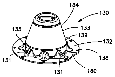
the piston retaining or stop feature needed to be replaced. The other problem
was
that the spring needed to be guided in a different manner.
[0005] The piston stop function was accomplished by forming two flange
extensions 37 in the flange area 32 of the non-pressure head 30', as shown in
Figure 2. The flange extensions 37 are approximately 713/16" apart, which is
less
that the OD of the piston 24. When the piston 24 contacted these flat features
37,
the piston 24 stopped traveling, thus retaining the piston in the cylinder
bore. A
piece of plastic 48 was designed in a helical shape at the same pitch as the
return
spring 46 in its free state. It is thick enough to evenly fill the gap between
the
piston rod 26 and the return spring 46 and act as a guide.
[0006) The interface of the non-pressure head 30, 30' with the brake cylinder
I2 is
sealed by a gasket 50. The gasket 50, in conjunction with the piston rod
gasket,
seals the non-pressure cavity from the atmosphere, keeping contaminants out.
The
non-pressure cavity volume changes as the piston 24 strokes to and fro with
brake
cylinder signal. A vent is required to allow the non-pressure cavity volume to
react
to the change in volume. The vent 60 (shown in Figures 2 and 3) is built into
the
head portion 34. The vent cavity 60 is attached to the side of the head
portion 34.
CA 02503479 2005-04-O1
-2-
To keep debris out of the non-pressure cavity, the vent opening is filtered
with a
piece of open celled foam 62 held by clasp 64.
[0007] The location of the vent 60 is not at the lowest point of the non-
pressure
head's cavity. As a result, in the event of water intrusion, possibly through
condensation or gasket failure, the water cannot escape and corrosion results.
Because the vent housing 60, known as the strainer case, is welded to the side
of
the non-pressure head, it impedes stacking one non-pressure head on top of
another. This stackability is desirable because it facilitates efficient
shipping and
stocking. The labor intense welding process involved to secure the strainer
case
results in high product costs. Also, the two-sided piston stop 37 may not
support
the piston symmetrically causing uneven loading of the piston.
(0008) The presently disclosed non-pressure head for a fluid cylinder
addresses
these issues and includes a drain channel formed in the flange by a raised
portion
of the flange extending from a plane of the flange in the same direction as
the head
portion. The channel is cold formed in the flange. For the piston stop, the
flange
has an opening of a diameter smaller than a diameter of a piston on the piston
rod
to form a stop for the piston portion. A plurality of spaced ribs are provided
between the flange and the head. The ribs are raised portions of the flange
and the
head and are cold formed in the flange and the head.
[0009] The disclosed non pressure head may be part of a kit for a fluid
cylinder,
which further includes a compressible, porous material to be positioned
between a
pressure head and the flange and having a thickness at least as large as the
depth of
the channel. An annular gasket may also be in the kit, and the porous material
is
joined to the gasket.
[000'! 0] Also disclosed is a fluid cylinder having a pressure head and a non-
pressure
head joined at respective annular flanges and an annular gasket between the
flanges. A piston moves in the pressure head and is mounted to a piston rod
extending through and exiting the non-pressure head at an opening. A drain
channel is provided in the flange of the non-pressure head facing the channel.
The
drain channel is a raised portion of the flange extending from a plane of the
flange.
The channel is cold formed in the flange. A compressible, pomus material is
between the gasket and the flange of the non-pressure head and has a thickness
at
CA 02503479 2005-04-O1
-3-
least as large as the depth of the channel. The porous material is joined to
the
gasket as a unit.
[00011] These and other aspects of the present disclosure will become apparent
from the following detailed description of the disclosure, when considered in
conjunction with accompanying drawings.
BRIEF D>r CRIPTION OF THE DRAWINGS
[00012] Figure 1 is an exploded view of a first brake cylinder of the prior
art.
[00013] Figure 2 is as exploded view of a second brake cylinder of the prior
art.
[00014] Figure 3 is a perspective view of the non-pressure head of the brake
cylinder of Figure 2.
[00015] Figure 4 is a perspective view of a non-pressure head, according to
the
present disclosure.
[00018] Figure 5 is a side view including a gasket and foam, according to the
present disclosure.
[00017] Figure 6 is a bottom view of the non-pressure head of Figure 4.
[00018) Figure 7 is a perspective view of a dual port non-pressure head,
according
to the present disclosure.
DETAILED DESCRIrPTION OF THE PREFERRED EMBODIMENTS
(00019] The fluid brake cylinders of the prior art, shown in Figures I through
3,
will now be described in detail. Those elements which have the same structure
and/or function have the same reference numbers in the drawings. The brake
cylinder 10 includes a pressurized section 12, which includes a cylinder
portion 14
and a flange I6. Fastener openings 18 are provided in the flange 16. A packing
cup 20 and a guide ring 22 are mounted on a piston 24, which is mounted to
piston
rod or pipe 26. A non-pressure head 30 includes a flange 30 and a head portion
34
extending therefrom. A spring guide and piston stop 36 is welded to the head
portion 34. Fastener openings 38 are provided in the flange 32. A collar 40 is
held
fixed to the head portion 34 by a fastener 41.
[00020] A combined spring seat and bearing 42 is mounted within the non-
pressurized head 30. Combined swab retainer 44 and swab felt 45 are also
mounted in the head portion 34 and forms a seal about the piston rod 26.
Retainer
spring 46 rests on spring seat 42 and presses against the non-pressurized side
of the
piston 24. A gasket 50 is positioned between the flanges 16, 32 and includes
CA 02503479 2005-04-O1
-4-
fastener openings 58. Fasteners 52 extend through the fastener openings 18,
38, 58
and secure the pressure head 12 to the non-pressure head 30 with a nut 54. The
head portion 34 of the non-pressure head 30 includes a vent 60. Inserted in
the
vent 60 is a strainer or filter 62 retained therein by retainer 64. This may
be an
open foam material. The vent housing 60 is illustrated in Figure 3.
[00021 ] As previously noted, a later embodiment of the brake cylinder is
illustrated
in Figure 2. The major differences are that the piston stop aad spring guide
36 has
been removed. Spring guide 48 has replaced the spring guide portion 36. The
stops are extended flange portions 37 formed by flats 39 formed is the
generally
conical portion of the head 34. As previously noted, the vent housing 60 is
welded
to the side of the head portion 34.
[00022] The brake cylinder of Figure 1 is Part No. 704874 and that of Figure 2
is
Part No. 762838, both of which are available from New York Air Brake
Corporation of Watertown, New York.
[00023] A non-pressure head is illustrated in Figures 4-7. The same tens and
unit
numbers are used corresponding to that of the prior art of Figures 1-3 and
have the
same purpose and function. A non-pressure head 130 includes a flange 132 and a
head portion 134. The head portion 134 includes a generally non-tapered
portion
132 to which is connected the tapering portion 133. The generally non-
cylindrical
or flat portions 139 are continuous and form a basically continuous stop
region 137
of the flange 132, as illustrated specifically in Figure 6. To strengthen the
flange
and the stop portions, a plurality of spaced ribs 131 are provided between the
flange 132 and flat portions 139 of head portion 134. The ribs 131 are cold
formed
and are part of the process of forming the unitary non-pressure head 130.
[00024] A portion of the flange 132 is raised at 160 to provide the drainage
duct or
vent 160. Thus, a drainage duct would be between the flange 132 and the gasket
50. A filter 162 is positioned in the duct 160 between the gasket 50 and the
flange
132. The thickness T of the filter 162 is greater than the depth D of the
channel
160, as illustrated in Figure 5. It should also be noted that, as illustrated,
the filter
material 162 may be joined to the gasket 50 as a unitary unit. This may be by
adhering it thereto as a single unit.
CA 02503479 2005-04-O1
-5-
[00025) A non-pressure head 130 and the filter material 162 may be provided as
a
kit with or without the gasket 50. Alternatively, gasket 50, as a separate
element or
with the strainer material 162 as a unit, may also be provided in a kit.
(00026) When the non-pressure head 130 is joined to the cylinder or pressure
head
12, the strainer material 162 is compressed and fills the depth D of the
channel
formed by the raised portion 160. This places the drainage or vent at the
lowest
possible point and thereby improves the drainage of liquid from the non-
pressure
head 130. The channel or duct formed by the raised portion 160 is cold formed
during the formation of the non-pressure head 130.
(000277 .Although only one duct 160 is shown in Figures 4-6, two such ducts
160A,
160B are shown in Figure 7. Other ducts may be provided.
(00028) By providing the ribs 131, the thickness of the material used for
forming
the non-pressure head 130 has been reduced. This not only reduces cost, but it
reduces the weight of the cylinder. Thickness has been reduced, for example,
from
136/1,000 of an inch to 104J1,000 of an inch. This has resulted in a 31
percent
reduction in weight for approximately 2.9 pounds. By providing a substantially
continuous stop surface 137 on the flange 132, a substantially greater stop
surface
has been provided, thereby providing a more symmetrical stop surface and
distribution of the forces. By eliminating the vent housing 60 as a separate
piece,
the cost of welding is eliminated. Also, making an integral raised portion of
the
flange 132 makes the non-pressure head 130 stackable and therefore more
economical to ship and store.
(00029) Although the present disclosure has been described and illustrated in
detail,
it is to be clearly understood that this is done by way of illustration and
example
only and is not to be taken by way of limitation. The scope of the present
disclosure is to be limited only by the terms of the appended claims.