Note: Descriptions are shown in the official language in which they were submitted.
CA 02503485 2009-01-07
1
TITLE
MODULAR PAINTING APPARATUS
= 5
BACKGROUND OF THE INVENTION
The present invention relates generally to robotic, painting systems and, in
particular, to an apparatus, method, and system for painting external surfaces
of vehicle
bodies.
Prior art paint booths are well known. A typical prior art paint booth, used
.to
paint- the exterior surfaces Of vehicle bodies in both continuous conveyance
and stop
station systems, includes an enclosure housing a plurality of paint
applicators. In one
configuration, the applicators are mounted on an inverted U-shaped. support
structure that
includes two vertical supports, one on either side of the path of travel of
the bodies, .
connected at their tops by a horizontal support. This support structure is
used to paint the
- 20. top surfaces of the body and the horizontal beam can be fixed
or can have an additional
degree of freedom to move along the top of the vehicle body being painted.
Another
= painting device is used in the same painting zone to paint
the sides of the body and
generally does not have the capability to move laterally along the length of
the body.
Disadvantages of this type of painting apparatus include lack of flexibility
to provide
optimized standoff distance between the body Surface and the applicator along
with
inefficient use of the allotted painting cycle time. In the case of the top
surface painting
machine, the paint applicators are mounted on a common beam: therefore, the
distance
between each paint applicator and the surface to be painted varies with the
contours of
= the vehicle body. In the Case of the side painting
machine, the paint applicators do not
- 30 move transverse to the path of the vehicle body. They can only
paint the portion of the
-
body that is in front of the applicator leaving a good portion of the
available cycle time
unused.
=
,
=INI.c;t = t...A)
-.g ,a7,1
118,10-2004r." CA 02503485 2005-04-25
,030333601W'
lune/2004 06:09 7345429569 MACMILLAN SOBANSKI
rAGE 11/11 ¨
== = Background art is disclosed in U. S. Patent Nos. 4,781, 517,
which describes a
robotic tool supported on a gantry above a workplace; II S. Patent 4,721,630,
which
teaches robots fixed in position to paint an object; and U. S. Patent
5,240,745, in which
illustrates paint spray guns supported on a cross beam at constant distances
from a
5 workplace surface.
IA
..MENDED SHEET
- EmPf t :-18/10/2004 44:13 = C1111-/I .1 If P
;OH = .
WO 2004/037430 CA 02503485 2005-04-25PCT/US2003/033601
An alternative to the support structure has been floor-mounted robots disposed
along the sides of the painting booth. The robots mount either spray guns or
rotary
applicators (bell machines) for directing atomized paint toward the vehicle
body.
While rotary applicators have advantages over spray guns, there are some
associated disadvantages. The prior art floor mounted robots, especially bell
machines,
are inherently very costly and limit visual access to the booth. The bell
machines require
more bells for the same throughput due to limited orientation capability. The
additional
bells use more paint per vehicle due to per bell paint waste during color
changing. Prior
art floor mounted robots also require significant booth modification when
installed in
existing paint booths, increasing installation time and cost, and require more
booth length
and width. The rail axis of floor mounted robots requires doors at both ends
of the
booth. The waist axis of the floor mounted robot requires an additional safety
zone at the
ends of the spray booth and the rail cabinets of the floor mounted robots
encroach into
the aisle space. Floor mounted robots also require frequent cleaning due to
the down
draft of paint overspray causing paint accumulation on the robot arm and base,
which
results in higher maintenance and cleaning costs.
The prior art bell zone machines also lack flexibility. Additional and more
flexible robot zones are required because the prior art machines unable to
reach
substantially all paintable surfaces on one side of the body and, therefore,
have limited
backup capability for an inoperative painting machine. Additional robot zones
are also
used to provide backup capability for the less flexible prior art painting
machine.
It is desirable, therefore, to provide a painting apparatus and a painting
system
that utilizes robots in an efficient and cost-effective manner that minimizes
paint waste,
occupies little space (length and width) in the paint booth and can be
installed in existing
paint booths without requiring significant booth modification. It is also
desirable to
provide a painting apparatus wherein one painting robot is able to reach
substantially all
paintable surfaces on one side of the article to provide backup capability in
the case of an
inoperative robot.
SUMMARY OF THE INVENTION
The present invention concerns an apparatus, method, and system for painting
objects in a paint booth or similar enclosure.
2
WO 2004/037430 CA 02503485 2005-04-25 PCT/US2003/033601
The present invention concerns a modular elevated rail adapted to be mounted
in
a paint booth for automated painting of conveyed articles such as automotive
vehicle
bodies. The modular elevated rail includes a frame enclosure having overhead-
mounted
rails straddling the line of conveyance of the articles. The conveyed articles
may be
moving or stationary during the painting process. The frame enclosure allows
for higher
rigidity and lower weight than is attained by conventional free standing,
cantilevered rail
mounts and occupies less space and realizes lower cost and less floor loading.
At least
one painting robot is mounted on a mounting location on the rail frame to move
alongside, and at a higher elevation than, the articles such as to protect the
rails from
paint overspray and reduce the cost of covers for, maintenance of, and
cleaning of the
rails. The elevated rail frame in accordance with the present invention may be
advantageously incorporated as part of a new paint booth assembly or installed
as a
retrofit device without requiring significant modification to the existing
paint booth. The
tubular arrangement of the modular elevated rail allows pre-wiring to be done
at the
production facility as opposed to an on-site wiring installation, providing
numerous cost
and quality-control benefits.
Preferably, a robot that provides four degrees of freedom is mounted on the
frame
rail, which provides another axis of freedom. The robot mounting location
allows one
painting robot to reach substantially all paintable surfaces on one side of
the article in a
degraded mode of operation. Preferably, opposed robots are provided for
symmetric
painting of the article. The robot primary axes (robot arms) advantageously
operate in a
vertically extending planar space. When an axi-symmetric paint applicator,
such as a
rotary bell, is mounted on the robot for painting, a sixth degree of freedom
(orientation
about the robot wrist faceplate) is not required as in the prior art. The
sixth degree of
freedom may be added if the application requires an asymmetric applicator.
The combination of the arm geometry of the robot and the mounting location of
the elevated rail provides higher bell on time with minimal impact on booth
size,
allowing fewer robots to be installed in a small booth, and permitting use for
painting in
the space provided by existing booths.
3
WO 2004/037430 CA 02503485 2005-04-25PCT/US2003/033601
DESCRIPTION OF THE DRAWINGS
The above, as well as other advantages of the present invention, will become
readily apparent to those skilled in the art from the following detailed
description of a
preferred embodiment when considered in the light of the accompanying drawings
in
which:
Fig. 1 is a perspective view of a modular elevated rail apparatus in
accordance
with the present invention;
Fig. 2 is fragmentary perspective view of an alternate embodiment of the
elevated
rail apparatus according to the present invention shown installed in a
painting booth;
Fig. 3 is a fragmentary cross sectional view of a portion of the elevated rail
apparatus of Fig. 1 installed in a painting booth in a first configuration;
Fig. 4 is a fragmentary cross sectional view similar to Fig. 3 showing the
elevated
rail apparatus installed in a painting booth in a second configuration;
Fig. 5 is a perspective view of one of the painting robots shown in Fig. 1;
and
Fig. 6 is a front elevation view of the elevated rail apparatus of Fig. 1
installed in
a painting booth for painting a vehicle body.
DESCRIPTION OF THE PREFERRED EMBODIMENT
There is shown in Fig. 1 a modular elevated rail apparatus 10 for painting
articles
or objects in accordance with the present invention. The elevated rail
apparatus 10 is
adapted to be disposed in a paint booth as discussed below. The apparatus 10
includes a
pair of frame rails 11 extending in a horizontal direction and spaced apart a
predetermined distance on opposite sides of an axis 12 defining a path of
travel for
objects to be painted. Each end of each of the frame rails 11 is supported on
an upper
end of an associated one of a plurality of legs 13 adapted to engage a floor
of the painting
booth. Corresponding ends of the frame rails 11 can be connected by cross
support
members 14 that cooperate with the frame rails 11, the legs 13 and the booth
floor to
form a modular, supporting rigid box frame structure of the apparatus 10. If
required for
support, additional ones of the legs 13 and the members 14 can be attached
intermediate
the ends of the frame rails 11. The cross supports 14 may be substituted by a
booth
structure specifically designed to couple the two frame rails 11 in a rigid
box frame
structure.
4
WO 2004/037430 CA 02503485 2005-04-25 PCT/US2003/033601
The frame rails 11 each have at least one mounting base 15 attached thereto.
Three such bases 15 are shown on each of the rails 11. Each of the mounting
bases 15 is
adapted to retain a painting device 16. The preferred painting device 16 is a
robotic four
axis articulated arm terminated at a free end by a paint applicator 17. The
arm includes a
shoulder axis, an elbow axis, a wrist rotating axis and a wrist tilting axis.
Although a
rotary bell atomizer is shown as the paint applicator 17, any known device
such as a
spray gun could be used. The painting device 16 and the mounting base 15 move
together parallel to the longitudinal axis 12 to provide a fifth axis of
movement. The
painting device 16 is provided with electrical power and fluids, such as
paint,
compressed air and solvent, through a flexible ribbon 18 connected between the
painting
device and the frame rail 11. Preferably, the painting devices 16 are mounted
in opposed
pairs for simultaneously painting opposite surfaces of an object such an
automobile body
or the like (not shown) conveyed through the apparatus 10 along the axis 12.
If the
shown location of the axis 12 represents the top surfaces of the objects being
painted, the
frame rails 11, the support members 14 and the mounting bases 15 may be
advantageously spaced a predetermined vertical distance 19 above the
horizontal plane
containing the axis 12.
The elevated rail apparatus 10 can easily be installed as a new painting booth
is
constructed, or as a retrofit to an existing paint booth without requiring
significant
modification to the existing paint booth. The frame rails 11, the legs 13 and
the support
members 14 can be brought into a painting booth and assembled into the rigid
frame
structure. Although the elevated rail apparatus 10 is described in terms of a
painting
process, the paint applicator 17 can be any tool suitable for performing a
process on an
object conveyed to the space between the two rails 11.
An alternate embodiment of the elevated rail apparatus according to the
present
invention is shown in Fig. 2 as an apparatus 20 installed in a painting booth
21. The
painting booth 21 includes a rear or exit wall 22, a lower wall or floor 23, a
front or
entrance wall 24, a pair of side walls 25 and a top wall or roof 26. The right
side wall 25,
the front wall 24 and the top wall 26 are cut away to permit the interior of
the booth 21 to
be seen. The walls 22 through 26 are connected together to define an enclosed
space in
which the elevated rail apparatus 10 of Fig. 1 may be advantageously disposed.
However, the alternate embodiment elevated rail apparatus 20 is adapted to be
disposed
5
CA 02503485 2009-01-07
0
in an upper portion of the paint booth 21 on the side walls 25. The apparatus
20 includes
the frame rail 11 extending along an interior surface of the left side wall
25. The frame
rail 11 can be attached to the side_ wall 25 by any suitable means. A second
one of the
frame rails 11 (not shown) is positioned on the opposite interior surface of
the right side
wall 25 such that the booth connects the frame rails 11 in a rigid frame
structure.
Movably attached to the frame rails 11 are the mounting bases 15 with the
painting
devices 16 and the painting applicators 17.
There is shown in FIG. 3 a portion of the apparatus 10 at a side wall of the
=
painting booth. The side wall is split with an upper portion 25a above the
frame rail 11
and a lower portion 25b below. The frame rail 11 has four side surfaces 1 la-
lid. The
upper portion 25a abuts an upper surface 1 la of the frame rail 11 near an
outer side
surface lib. The lower portion 25b abuts a lower surface 11c of the frame rail
11 near
an inner side surface lid to which the cross support member 14 is attached.
Thus, the
frame rail 11 forms a part of the side wall separating an interior space 27 of
the painting
booth from an aisle 28 outside the booth. The frame rails 11 are made of
tubular stock
and are preferably rectangular in cross section having a hollow interior lie.
Alternatively, the frame rails 11 are formed from any shape of tubular stock
including,
but not limited to, circular stock. A coupling conduit 29 is attached to the
surface 1lb
for routing electrical and fluid lines from the aisle 28 into the interior lie
of the frame
rail 11. The cross support members 14 also are tubular for routing electrical
and fluid
lines. The frame rails 11 and the cross supports 14 can be sealed, purged and
pressurized to function in the painting booth environment.
There is shown in Fig. 4 a portion of the apparanis 10 at the side wall 25 of
the
=
painting booth wherein the entire apparatus 10 is located in the interior 27
of the booth.
A coupling conduit 30 is attached to the surface lib for routing electrical
and fluid lines
into the interibr lie of the frame rail 11. The coupling conduit 30 extends
through the
side wall 25 into the aisle 28.
Elevating the frame rails 11 above the path of the upper surfaces of the
objects
being painted allows a simple means for connecting the cross support members
14
between the opposing frame rails providing a path for any supply lines. Thus,
the
electrical power and fluid sources can be located in the aisle 28 adjacent the
exterior of
the left side wall 25, for eXample, to supply the painting devices 16 on both
sides of the
6
sm.a.,rowieltswePt
= 4, V11,04.-q-,
WO 2004/037430 CA 02503485 2005-04-25PCT/US2003/033601
booth. Also, it is advantageously less costly than adding support steel to the
paint booth
to support the cantilever loads of traditional prior art floor mounted robot
rails.
In addition, elevating the frame rails 11 places many of the typical
maintenance
components such as linear axis drive components and cable and hose carriers
(not
shown) out of the area where the paint overspray would typically accumulate on
equipment in a prior art down draft spray booth. These components do not need
to be
protected against the overspray as diligently as a prior art floor mounted
rail. This
advantageously lowers the cost for protective covers and seals (not shown)
while
lowering the ongoing maintenance cost over the life of the robots 16.
Elevating the
frame rails 11 also permits unobstructed viewing into the paint booth 21,
through
windows 31 (see Fig. 2) provided in the side wall 25, which is a benefit for
system
operators. The elevated rail apparatus 10 and 20 also allows access doors (not
shown) to
be placed in the side walls 25 when they would typically be located at the
rear wall 22
and the front wall 24 of the booth 21. This again reduces the overall length
of the booth
21.
Furthermore, elevating the frame rails 11 above the object, such as a vehicle
body, to be painted allows the booth 21 to be made narrower than required for
a
traditional five to seven axis robot and does not require installation of
components in the
aisle 28 that are typically found in prior art floor-mounted installations.
The elevated
frame rail 11 and the robots 16 also advantageously allow the arm of each of
the robots,
discussed in more detail below, to reach under itself and paint the side of
the vehicle
because the robot base is not trapped between the side wall 25 and the
vehicle.
As shown in Figs. 1 and 2, a plurality of the articulated arm robots 16 is
attached
to the elevated frame rails 11 at various mounting bases 15 that move along
the rails and
allow the applicators 17 to follow an object to be painted, such as a vehicle
body (not
shown), as it moves through the paint booth 21. The applicators 17 are
preferably a
circular spray pattern bell applicator. By installing multiple articulated arm
robots 16 on
the common frame rails 11, the vehicle can be processed with each applicator
17
spraying for a higher percentage of time, and requiring fewer of the robots 16
and
corresponding applicators 17 as compared to floor mounted systems.
With a simplified robot 16, the design of the structural elements of the
elevated
rail apparatus 10 and 20 (the frame rail 11, the legs 13 and the cross
supports members
7
WO 2004/037430 CA 02503485 2005-04-25 PCT/US2003/033601
14) are fit within the narrow width space limitations of a standard bell zone
paint booth
21. Furthermore, utilizing the elevated rail apparatus 10 in conjunction with
the higher
flexibility of a multi-axis manipulator, discussed in more detail below,
yields higher
application efficiencies, and thereby reduces the length overall length of a
traditional bell
zone paint booth 21.
As shown in Fig. 5, the preferred painting device 16 is a four axis
articulated arm
robot terminated at a free end of the arm by the paint applicator 17 shown as
a rotary bell
applicator. The robot 16 includes a first or inner arm portion 32 mounted at a
first end to
a robot base 33 for rotation about a shoulder axis 34. A second or outer arm
portion 35 is
mounted at a first end to a second end of the inner arm 32 for rotation about
an elbow
axis 36. A wrist 37 attaches the paint applicator 17 to a second end of the
outer arm 35
and has a rotating axis 38 and a tilting axis 39. The wrist 37 rotates the
applicator 17
about the axis 38 which is generally parallel to a longitudinal axis of the
outer arm 35
and rotates the applicator 17 about the axis 39 to tilt the applicator
relative to the axis 38.
Thus, the robot 16 provides four axes of motion relative to the base 33 for
movement of
the arm portions 32 and 35, the wrist 37 and the applicator 17 in vertical
planes. A fifth
axis of motion is a rail axis 40 provided through the attachment of the robot
base 33 to
the mounting base 15 (Fig. 1) for reciprocating movement of the robot 16 along
the
horizontal longitudinal axis of the associated frame rail 11 (Fig. 1).
Preferably, the structural components of the outer arm portion 35 and the
wrist 37
are formed from a non-conductive material having suitable structural strength
and
impervious to the corrosive properties of solvents used in the painting
environments,
such as Lauramid A material. "Lauramid" is a registered trademark of Albert
Handtmann ELTEKA Verwaltungs-GmbH of Biberach, Germany. The Lauramid A
material is a castable polyamide Nylon 12G material that also provides for
electrostatic
isolation, cleanliness, cleaning capability, and weight advantages. Grounding
of internal
gearing (not shown) in the wrist 37 and other conductive components is not
necessary for
use in the paint booth 21 because they are suitably insulated. Non-grounded
components
are advantageously less likely to attract paint overspray resulting in a
cleaner robot 16
requiring less maintenance and having better transfer efficiency of the paint
to the
vehicle, all resulting in less operating cost. The conductive components could
also be
charged at a lower or the same potential as the spray applicator.
8
WO 2004/037430 CA 02503485 2005-04-25 PCT/US2003/033601
A plurality of paint lines 41 is routed along the side of the inner arm 32 and
connect to a color changer 42 mounted in the outer arm 35. The outer arm 35
houses a
paint canister (not shown) for receiving a supply of paint through a selected
one of the
lines 41 and dispensing the paint to the applicator 17. Also housed within the
outer arm
35 is a high voltage cascade (not shown) for electrostatically charging the
paint for
application to the object being painted.
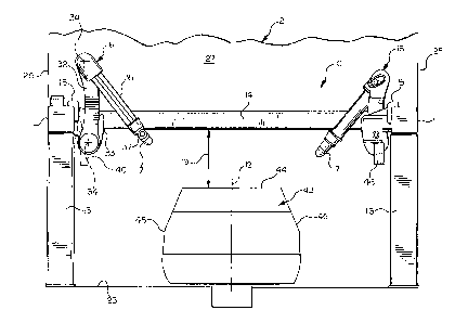
Fig. 6 shows the elevated rail apparatus 10 installed in the interior 27 of
the
painting booth 21 for painting a vehicle body 43. The base 33 and the shoulder
axis 34
of each of the robots 16 are located above the horizontal plane of the axis 12
of
movement of an upper surface 44 of the vehicle body 43 which maximizes the
capability
of the robots. A one of the robots 16 dedicated to painting the top 44 of the
vehicle body
43 can advantageously paint a side 45 of the vehicle body if necessary in a
degrade mode,
such as if a one of the robots 16 dedicated to painting the side fails,
because of the
extension capabilities that the translation axes 34 and 36 provide. In
addition, the
elevated frame rails 11 and cross support members 14 allow for the placement
of an
enclosed process controller 46 (Figs. 5 and 6), which includes pneumatic
valves and bell
control components (not shown), below the robot base 33 and in the paint booth
21, in an
easily accessible type X purge enclosure.
The robot 16 being attached to the movable mounting base 15 on the elevated
frame rail 11 allows the applicator 17 to follow the vehicle body 43 as it
moves through
the booth 21. By utilizing multiple opposed robots 16 on opposed frame rails
11, and by
using a line tracking motion capability, the vehicle body 43 can be painted
with each
applicator 17 spraying for a high percentage of the available cycle time. For
example, the
robots 16 adjacent to the exit wall 22 (Fig. 2) can be spraying a portion of
one vehicle
body while the robots 16 adjacent to the entrance wall 24 can be spraying a
portion of
another vehicle body. Alternatively, if the vehicle body is conveyed to a stop
within the
space between the two rails 11, the robots 16 may still move along the rails
to reach and
paint all body surfaces desired to be painted.
The robot primary axes 34 and 36 advantageously operate the robot arm portions
32 and 35 in a vertically extending planar space orthogonal to the axis 12.
Opposed
robots 16 are provided for symmetric painting of objects such as the vehicle
body 43.
Preferably control lines (not shown) are run through, or along, the cross
support members
9
WO 2004/037430 CA 02503485 2005-04-25PCT/US2003/033601
14 in order for a single controller (not shown) to control a pair of the
opposed robots 16
for painting the opposite sides of the vehicle body 43.
The geometry of the robot 16 and the mounting base 15 allows one painting
robot
to reach substantially all paintable surfaces on the top 44 and one side 45 of
the vehicle
body 43 in a degraded mode of operation. The elevated rail apparatus 10 or 20
advantageously provides for the use of multiple robots 16 on the same frame
rail 11
having the capability to paint various size vehicle bodies 43 within the paint
booth 21.
The geometry of the robot 16 and the elevated mounting location also
eliminates human
safety issues associated with placing traditional prior art robots in
proximity of manual
spray zones. Because the robot 16 is a planar device operating in a plane
orthogonal to
the longitudinal axis of the frame rail 11 and does not have a waist axis as
in the prior art
floor mounted painting robots and rail robot systems, the robot 16 does not
extend the
applicator 17 beyond the ends of the spray zone with an appreciable reduction
in booth
length. Furthermore, the geometry of the robot 16 and the elevated mounting
location
allows the robot to extend underneath the frame rail 11 into a protected
enclosure (not
shown) so that the robot can be serviced while the remaining robots 16 in the
paint booth
21 continue painting. The protected enclosure has provisions for use of
dynamic limiting
devices to ensure operator safety.
In accordance with the provisions of the patent statutes, the present
invention has
been described in what is considered to represent its preferred embodiment.
However, it
should be noted that the invention can be practiced otherwise than as
specifically
illustrated and described without departing from its spirit or scope.
10