Some of the information on this Web page has been provided by external sources. The Government of Canada is not responsible for the accuracy, reliability or currency of the information supplied by external sources. Users wishing to rely upon this information should consult directly with the source of the information. Content provided by external sources is not subject to official languages, privacy and accessibility requirements.
Any discrepancies in the text and image of the Claims and Abstract are due to differing posting times. Text of the Claims and Abstract are posted:
| (12) Patent: | (11) CA 2503762 |
|---|---|
| (54) English Title: | A PERFORATED DECK MADE OUT OF A PLURALITY OF SEGMENTS |
| (54) French Title: | TOLE PERFOREE CONSTITUEE DE PLUSIEURS SEGMENTS |
| Status: | Expired and beyond the Period of Reversal |
| (51) International Patent Classification (IPC): |
|
|---|---|
| (72) Inventors : |
|
| (73) Owners : |
|
| (71) Applicants : |
|
| (74) Agent: | GOWLING WLG (CANADA) LLPGOWLING WLG (CANADA) LLP |
| (74) Associate agent: | |
| (45) Issued: | 2012-10-09 |
| (22) Filed Date: | 2005-04-05 |
| (41) Open to Public Inspection: | 2005-10-19 |
| Examination requested: | 2010-03-29 |
| Availability of licence: | N/A |
| Dedicated to the Public: | N/A |
| (25) Language of filing: | English |
| Patent Cooperation Treaty (PCT): | No |
|---|
| (30) Application Priority Data: | ||||||
|---|---|---|---|---|---|---|
|
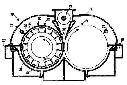
A cylindrical rotating thickening device including an axial core, a plurality of longitudinally extending spaced apart support ribs extending radially from the axial core, and a shell surrounding the support ribs and supported thereon. The shell includes a plurality of longitudinally extending spaced apart grooves, and a perforated deck surrounding and supported on the shell. The deck includes a plurality of closely adjacent deck segments, and each deck segment includes a leading edge and a trailing edge. Each deck segment further includes an integral bar attached to the leading edge and received in the shell groove, and a plurality of fasteners for securing the bar to the shell.
Dispositif d'épaississement rotatif cylindrique comprenant un noyau axial, plusieurs nervures de support espacées sur le plan longitudinal et d'étendant radialement à partir du noyau axial, et une coquille entourant les nervures de support et supportées par ces dernières. La coquille comprend une série de gorges espacées s'étendant sur le plan longitudinal et une tôle perforée entourant la coquille et supportée sur cette dernière. La tôle comprend plusieurs segments adjacents rapprochés, et chaque segment de tôle comporte un bord avant et un bord arrière. Chaque segment de tôle comprend également une barre intégrée attachée au bord avant et logeant dans la gorge de la coquille, ainsi que plusieurs fixations pour fixer la barre à la coquille.
Note: Claims are shown in the official language in which they were submitted.
Note: Descriptions are shown in the official language in which they were submitted.
2024-08-01:As part of the Next Generation Patents (NGP) transition, the Canadian Patents Database (CPD) now contains a more detailed Event History, which replicates the Event Log of our new back-office solution.
Please note that "Inactive:" events refers to events no longer in use in our new back-office solution.
For a clearer understanding of the status of the application/patent presented on this page, the site Disclaimer , as well as the definitions for Patent , Event History , Maintenance Fee and Payment History should be consulted.
| Description | Date |
|---|---|
| Inactive: IPC expired | 2019-01-01 |
| Time Limit for Reversal Expired | 2016-04-05 |
| Letter Sent | 2015-04-07 |
| Letter Sent | 2014-12-29 |
| Grant by Issuance | 2012-10-09 |
| Inactive: Cover page published | 2012-10-08 |
| Pre-grant | 2012-07-24 |
| Inactive: Final fee received | 2012-07-24 |
| Notice of Allowance is Issued | 2012-03-15 |
| Letter Sent | 2012-03-15 |
| Notice of Allowance is Issued | 2012-03-15 |
| Inactive: Approved for allowance (AFA) | 2012-03-13 |
| Amendment Received - Voluntary Amendment | 2011-12-01 |
| Inactive: S.30(2) Rules - Examiner requisition | 2011-06-03 |
| Letter Sent | 2010-04-20 |
| Request for Examination Received | 2010-03-29 |
| All Requirements for Examination Determined Compliant | 2010-03-29 |
| Request for Examination Requirements Determined Compliant | 2010-03-29 |
| Letter Sent | 2009-06-19 |
| Inactive: Correspondence - Transfer | 2008-11-27 |
| Letter Sent | 2007-05-08 |
| Reinstatement Requirements Deemed Compliant for All Abandonment Reasons | 2007-04-20 |
| Deemed Abandoned - Failure to Respond to Maintenance Fee Notice | 2007-04-05 |
| Inactive: IPC from MCD | 2006-03-12 |
| Application Published (Open to Public Inspection) | 2005-10-19 |
| Inactive: Cover page published | 2005-10-18 |
| Inactive: First IPC assigned | 2005-09-04 |
| Letter Sent | 2005-06-28 |
| Letter Sent | 2005-06-28 |
| Inactive: Single transfer | 2005-06-03 |
| Inactive: Courtesy letter - Evidence | 2005-05-17 |
| Inactive: Filing certificate - No RFE (English) | 2005-05-13 |
| Application Received - Regular National | 2005-05-13 |
| Filing Requirements Determined Compliant | 2005-05-13 |
| Inactive: Single transfer | 2005-04-29 |
| Abandonment Date | Reason | Reinstatement Date |
|---|---|---|
| 2007-04-05 |
The last payment was received on 2012-04-05
Note : If the full payment has not been received on or before the date indicated, a further fee may be required which may be one of the following
Please refer to the CIPO Patent Fees web page to see all current fee amounts.
| Fee Type | Anniversary Year | Due Date | Paid Date |
|---|---|---|---|
| Registration of a document | 2005-04-05 | ||
| Application fee - standard | 2005-04-05 | ||
| Registration of a document | 2005-04-29 | ||
| Reinstatement | 2007-04-20 | ||
| MF (application, 2nd anniv.) - standard | 02 | 2007-04-05 | 2007-04-20 |
| MF (application, 3rd anniv.) - standard | 03 | 2008-04-07 | 2008-03-18 |
| Registration of a document | 2008-06-16 | ||
| MF (application, 4th anniv.) - standard | 04 | 2009-04-06 | 2009-04-06 |
| Request for examination - standard | 2010-03-29 | ||
| MF (application, 5th anniv.) - standard | 05 | 2010-04-06 | 2010-04-06 |
| MF (application, 6th anniv.) - standard | 06 | 2011-04-05 | 2011-03-22 |
| MF (application, 7th anniv.) - standard | 07 | 2012-04-05 | 2012-04-05 |
| Final fee - standard | 2012-07-24 | ||
| MF (patent, 8th anniv.) - standard | 2013-04-05 | 2013-03-19 | |
| MF (patent, 9th anniv.) - standard | 2014-04-07 | 2014-03-31 | |
| Registration of a document | 2014-12-16 |
Note: Records showing the ownership history in alphabetical order.
| Current Owners on Record |
|---|
| GL&V CANADA INC. |
| Past Owners on Record |
|---|
| DAVID L. SICELY |

