Language selection

Search

Patent 2504033 Summary

Third-party information liability

Some of the information on this Web page has been provided by external sources. The Government of Canada is not responsible for the accuracy, reliability or currency of the information supplied by external sources. Users wishing to rely upon this information should consult directly with the source of the information. Content provided by external sources is not subject to official languages, privacy and accessibility requirements.

Claims and Abstract availability

Any discrepancies in the text and image of the Claims and Abstract are due to differing posting times. Text of the Claims and Abstract are posted:

  • At the time the application is open to public inspection;
  • At the time of issue of the patent (grant).
(12) Patent: (11) CA 2504033
(54) English Title: FUEL FILTER FOR DIESEL ENGINES WITH HIGH PRESSURE DIRECT INJECTION OF COMMON RAIL TYPE AND THE LIKE
(54) French Title: FILTRE DE CARBURANT POUR MOTEUR DIESEL A INJECTION DIRECTE SOUS HAUTE PRESSION DU TYPE DE SYSTEME A GALERIE COMMUNE ET ANALOGUE
Status: Expired and beyond the Period of Reversal
Bibliographic Data
(51) International Patent Classification (IPC):
  • F02M 37/24 (2019.01)
  • B01D 36/00 (2006.01)
(72) Inventors :
  • GIRONDI, GIORGIO (Italy)
(73) Owners :
  • UFI FILTERS S.P.A.
(71) Applicants :
  • UFI FILTERS S.P.A. (Italy)
(74) Agent: ROBIC AGENCE PI S.E.C./ROBIC IP AGENCY LP
(74) Associate agent:
(45) Issued: 2011-03-29
(86) PCT Filing Date: 2003-10-24
(87) Open to Public Inspection: 2004-06-17
Examination requested: 2008-04-07
Availability of licence: N/A
Dedicated to the Public: N/A
(25) Language of filing: English

Patent Cooperation Treaty (PCT): Yes
(86) PCT Filing Number: PCT/EP2003/012059
(87) International Publication Number: EP2003012059
(85) National Entry: 2005-04-26

(30) Application Priority Data:
Application No. Country/Territory Date
RE2002A000094 (Italy) 2002-12-03

Abstracts

English Abstract


Fuel filter for diesel engines with high pressure direct injection of common
rail type and the like, comprising an outer casing provided with a fuel inlet
conduit (3) and an outlet conduit (4), and containing in its interior a filter
means(5), a temperature sensor(15) being positioned in proximity to the bottom
of said casing to measure the temperature of the fuel present in the casing.


French Abstract

La présente invention a trait à un filtre de carburant pour moteurs diesel à injection directe sous haute pression du type de système à galerie commune et analogue, comportant une enveloppe extérieure munie d'un conduit d'admission de carburant (3) et une conduit de sortie de carburant (4), et refermant en son sein un moyen de filtre (5), un capteur de température (15) étant disposé à proximité du fond de ladite enveloppe pour mesurer la température du carburant se trouvant dans l'enveloppe.

Claims

Note: Claims are shown in the official language in which they were submitted.

6
WHAT IS CLAIMED IS:
1. A fuel filter for diesel engines with high pressure direct injection of
common rail
type, comprising an outer casing provided with a fuel inlet conduit (3) and an
outlet
conduit (4), and internally housing a filter means (5), said casing comprising
an upper
chamber (6) for containing said filter means (5), a lower chamber (7)
communicating
with said upper chamber to collect the water which said filter means (5)
separates
from the fuel, and means (8) for measuring the level of the water collected in
the
lower chamber (7), characterised in that said means for measuring the water
level in
the chamber (7) comprise a temperature sensor for generating an electrical
signal,
said signal being fed to an electronic card by two conductors.
2. A filter as claimed in claim 1, characterised in that said means (8) for
measuring the level of the water collected in the lower chamber (7) comprises
a float
positioned in the lower chamber and having a specific gravity between the
specific
gravity of water and that of the fuel, and a float guide stem in the interior
of which
there is positioned a magnetic field sensor connected electrically to said
electronic
card by two conductors, said temperature sensor being positioned in the
interior of
said stem in proximity to its upper free end.
3. A filter as claimed in claim 2, characterised in that one of the conductors
connecting said temperature sensor to said card is also connected to said
magnetic
field sensor.
4. A filter as claimed in claim 1, characterised in that said temperature
sensor is
of NTC type.
5. A filter as claimed in claim 1, characterised in that said temperature
sensor is
embedded in a layer of conductive resin.

Description

Note: Descriptions are shown in the official language in which they were submitted.


CA 02504033 2005-04-26
WO 2004/051070 PCT/EP2003/012059
FUEL FILTER FOR DIESEL ENGINES WITH HIGH PRESSURE DIRECT
INJECTION OF COMMON RAIL TYPE AND THE LIKE
This invention relates to a filter for vehicle fuel, in particular for diesel
engines of common rail or high pressure direct injection type, and the like.
In these types of engine the fuel feed rate to the engine feed pump is
much greater than that required by the engine for its operation, as the fuel
is used not only as engine feed fluid but also as the lubrication fluid and
cooling fluid for the feed pump. That fuel not fed to the cylinders
io increases in temperature as it removes heat from the pump and is then
returned to the vehicle fuel tank.
It has been found that because of the high temperature at which the feed
pump operates, after a certain time of engine operation the fuel contained
in the vehicle tank or in the engine feed circuit attains a high temperature,
of the order of 100 C and beyond.
A requirement has therefore arisen to control the fuel temperature as too
high a fuel temperature could damage components of the engine feed
circuit. Moreover in these types of engine the fuel temperature has
become an essential parameter in regulating the fuel feed rate to the
engine. Measuring the fuel temperature has hence become necessary for
correct engine operation. The value of the measured temperature is fed
to the electronic control unit which controls fuel feed to the pump and
hence to the cylinders.
The known art has solved this need to control the fuel temperature by
temperature measurement devices positioned either inside the fuel tank or
along the conduits through which the fuel is fed to the engine.

CA 02504033 2010-05-21
2
In both cases the devices used require suitable fixing flanges and electric
cables for connecting the device to the vehicle electronic control unit.
Moreover it is often difficult to install said temperature measurement
devices as that engine region in which the conduits are present is
crowded with numerous components.
The object of the present invention is to overcome the drawbacks of the
known art within the context of a simple and rational solution of low cost.
According to the present invention, there is provided a fuel filter for diesel
engines
with high pressure direct injection of common rail type, comprising an outer
casing
l0 provided with a fuel inlet conduit (3) and an outlet conduit (4), and
internally housing
a filter means (5), said casing comprising an upper chamber (6) for containing
said
filter means (5), a lower chamber (7) communicating with said upper chamber to
collect the water which said filter means (5) separates from the fuel, and
means (8)
for measuring the level of the water collected in the lower chamber (7),
characterised
in that said means for measuring the water level in the chamber (7) comprise a
temperature sensor for generating an electrical signal, said signal being fed
to an
electronic card by two conductors.
Specifically, the invention provides a temperature measurement device
which is associated with the lower part of the fuel filter installed on the
20 vehicle.
According to a preferred embodiment of the invention, said temperature
measurement device is associated with the means for sensing the
presence of water accumulated in the bottom of the fuel filter.

CA 02504033 2010-05-21
3
In this respect it is known that the water present in the fuel tends to create
oxidation damage to the metal parts with which it comes into contact,
hence the latest generation of filters, in particular for diesel engine fuel,
separate not only the impurities but also the water present in the fuel.
As water has a specific gravity greater than the fuel, it collects on the
bottom of a collection chamber positioned in the lower part of the filter.
This water must be bled off on reaching a maximum level, to avoid it
interfering with correct filter operation, or it may be returned to the fuel
flow
leaving the filter.
1o Preferably, the water is bled off by suitable means which are activated
when a
suitable sensor senses that the water in said collection chamber has reached
its
maximum level.
Preferably, said means for sensing the water level comprise a float positioned
within
the collection chamber and having a specific gravity between the specific
gravity of
water and the specific gravity of the fuel. The float is mounted on a guide
stem, in the
interior of which a magnetic field sensor is positioned connected electrically
to an
electronic card by two conductors.
According to the invention, said stem also internally houses the
temperature sensor which measures the fuel temperature. Specifically,
20 said temperature sensor is housed in proximity to the free end of the stem,
which projects into the water collection chamber. To facilitate heat
conduction the sensor is embedded in a conductive resin which is poured
into the stem.

CA 02504033 2010-05-21
3a
The invention is described in detail hereinafter with the aid of the
accompanying figures, which illustrate a non-exclusive embodiment
thereof by way of example.
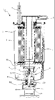
Figure 1 is a schematic illustration of the filter according to the invention;
Figure 2 is an enlarged view of the lower portion of Figure 1;
Figure 3 is an enlarged view of the lower portion of the filter, on which a
variant of the invention is installed.
Figure 1 shows a filter 1, substantially of known type, comprising an outer
casing 2 having a fuel inlet 3 and outlet 4. Said casing 2 houses internally
to a filter means 5 positioned within an upper chamber 6. The fuel enters the
chamber 6 through the inlet 3 and after passing through the filter means 5
leaves through the outlet 4.

CA 02504033 2005-04-26
WO 2004/051070 PCT/EP2003/012059
4
Below the chamber 6 and communicating therewith there is positioned a
chamber 7 separated from the former by a perforated base 50, which also
acts as a support element for the filter means 5.
The chamber 7 serves to collect the water which separates from the fuel
and is therefore filled with fuel in its upper part, the separated water
accumulating in the lower part.
On the base of the chamber 7 there is positioned a water level sensor 8
comprising a float 9, the specific gravity of which lies between the specific
gravity of water and that of the fuel, and which is positioned in the
1o collection chamber 7 under the influence of the level of the water A which
collects on the bottom. The float 9 is slidable along a vertical guide stem
12, which projects into the chamber 7 by passing through a lower port 70
located at the lowest point of the chamber and closed by the stem 12 in
collaboration with a seal gasket 122.
In the interior of the stem 12 there is positioned a magnetic field sensor
element 13, for example of reed or Hall type, which is activated when the
float, in moving upwards as the level of the accumulated water increases,
reaches a position in correspondence with the element 13.
The sensor element 13 is electrically connected to an electronic card 14
by two connection cables 130 and 131. Said card is connected to the
engine control unit. When, by the effect of the water collected in the
chamber 6, the float 10 reaches the level of the sensor 13, an electrical
signal is generated and by way of the two conductor cables 130 and 131
is sensed by the electronic card 14, which makes it available to the engine
electronic control unit, to warn the user by a warning lamp positioned on
the vehicle dashboard or by a different warning signal.

CA 02504033 2005-04-26
WO 2004/051070 PCT/EP2003/012059
When the water maximum level signal is generated, the control card 14
activates withdrawal means for the water collected in the chamber 7. Said
water withdrawal means are associated with the lower end of the filter 1,
but are not illustrated or described in detail as they are of known type.
s In the interior of the stem 12, in proximity to its free end, there is also
present a temperature sensor 15 embedded in a layer of conductive resin
150, to measure the temperature of the fuel present in the chamber 7, this
being equal to or at least indicative of the temperature of the fuel passing
through the filter 1.
io The sensor 15, for example of NTC type, is connected to the electronic
card by two conductors 16 and 17. The temperature value measured by
the sensor 15 is fed to the engine electronic control unit via the card 14.
Figure 3 shows a variant of the invention in which one of the conductor
cables connecting the sensor to the card 14 is also used as the conductor
cable connecting the sensor 15 to the card itself. Hence in this case there
is simplification of the electrical circuit connecting the sensors to the card
as the cable 20 is used as a common conductor.

Representative Drawing
A single figure which represents the drawing illustrating the invention.
Administrative Status

2024-08-01:As part of the Next Generation Patents (NGP) transition, the Canadian Patents Database (CPD) now contains a more detailed Event History, which replicates the Event Log of our new back-office solution.

Please note that "Inactive:" events refers to events no longer in use in our new back-office solution.

For a clearer understanding of the status of the application/patent presented on this page, the site Disclaimer , as well as the definitions for Patent , Event History , Maintenance Fee  and Payment History  should be consulted.

Event History

Description Date
Time Limit for Reversal Expired 2022-04-26
Letter Sent 2021-12-14
Letter Sent 2021-10-25
Inactive: Office letter 2021-09-29
Letter Sent 2021-04-26
Letter Sent 2020-10-26
Inactive: IPC deactivated 2020-02-15
Common Representative Appointed 2019-10-30
Inactive: First IPC assigned 2019-02-05
Inactive: IPC assigned 2019-02-05
Inactive: IPC expired 2019-01-01
Change of Address or Method of Correspondence Request Received 2018-12-04
Grant by Issuance 2011-03-29
Inactive: Cover page published 2011-03-28
Inactive: Final fee received 2011-01-13
Pre-grant 2011-01-13
Letter Sent 2010-09-13
Notice of Allowance is Issued 2010-09-13
Inactive: Approved for allowance (AFA) 2010-09-08
Inactive: Correspondence - MF 2010-08-10
Amendment Received - Voluntary Amendment 2010-05-21
Inactive: S.30(2) Rules - Examiner requisition 2010-01-07
Letter Sent 2008-06-16
Request for Examination Requirements Determined Compliant 2008-04-07
All Requirements for Examination Determined Compliant 2008-04-07
Request for Examination Received 2008-04-07
Inactive: IPC from MCD 2006-03-12
Inactive: Cover page published 2005-07-25
Letter Sent 2005-07-21
Inactive: Notice - National entry - No RFE 2005-07-21
Application Received - PCT 2005-05-16
National Entry Requirements Determined Compliant 2005-04-26
Application Published (Open to Public Inspection) 2004-06-17

Abandonment History

There is no abandonment history.

Maintenance Fee

The last payment was received on 2010-09-29

Note : If the full payment has not been received on or before the date indicated, a further fee may be required which may be one of the following

  • the reinstatement fee;
  • the late payment fee; or
  • additional fee to reverse deemed expiry.

Patent fees are adjusted on the 1st of January every year. The amounts above are the current amounts if received by December 31 of the current year.
Please refer to the CIPO Patent Fees web page to see all current fee amounts.

Owners on Record

Note: Records showing the ownership history in alphabetical order.

Current Owners on Record
UFI FILTERS S.P.A.
Past Owners on Record
GIORGIO GIRONDI
Past Owners that do not appear in the "Owners on Record" listing will appear in other documentation within the application.
Documents

To view selected files, please enter reCAPTCHA code :


To view images, click a link in the Document Description column (Temporarily unavailable). To download the documents, select one or more checkboxes in the first column and then click the "Download Selected in PDF format (Zip Archive)" or the "Download Selected as Single PDF" button.

List of published and non-published patent-specific documents on the CPD .

If you have any difficulty accessing content, you can call the Client Service Centre at 1-866-997-1936 or send them an e-mail at CIPO Client Service Centre.

({010=All Documents, 020=As Filed, 030=As Open to Public Inspection, 040=At Issuance, 050=Examination, 060=Incoming Correspondence, 070=Miscellaneous, 080=Outgoing Correspondence, 090=Payment})


Document
Description 
Date
(yyyy-mm-dd) 
Number of pages   Size of Image (KB) 
Description 2005-04-25 5 182
Drawings 2005-04-25 3 104
Abstract 2005-04-25 2 90
Claims 2005-04-25 2 45
Representative drawing 2005-04-25 1 46
Description 2010-05-20 6 214
Claims 2010-05-20 1 40
Representative drawing 2011-03-01 1 22
Reminder of maintenance fee due 2005-07-20 1 109
Notice of National Entry 2005-07-20 1 191
Courtesy - Certificate of registration (related document(s)) 2005-07-20 1 114
Acknowledgement of Request for Examination 2008-06-15 1 177
Commissioner's Notice - Application Found Allowable 2010-09-12 1 166
Commissioner's Notice - Maintenance Fee for a Patent Not Paid 2021-10-13 1 543
Commissioner's Notice - Maintenance Fee for a Patent Not Paid 2021-12-05 1 553
Courtesy - Patent Term Deemed Expired 2022-01-10 1 538
PCT 2005-04-25 11 375
Fees 2005-09-20 1 29
Fees 2006-09-12 1 35
Fees 2007-09-25 1 47
Fees 2008-09-23 1 43
Fees 2009-09-30 1 58
Correspondence 2010-08-09 1 45
Correspondence 2010-09-12 1 88
Fees 2010-09-28 1 53
Correspondence 2011-01-12 2 54
Fees 2011-09-25 1 35
Courtesy - Office Letter 2021-09-28 1 189