Note: Descriptions are shown in the official language in which they were submitted.
CA 02504073 2005-04-13
-1-
SECURING DEVICE FOR KNOCK-ON EARTHWORKING TOOL
FIELD OF THE INVENTION
The invention relates to earthworking tools, such as agricultural sweeps,
of the type which are held in wedging frictional engagement on the tines of
agricultural tillage implements. More particularly, the invention relates to
securing devices for preventing accidental release of such earthworking tools
from agricultural tillage implements.
BACKGROUND OF THE INVENTION
Agricultural sweeps are employed as earthworking tools in the
cultivation of soil. A typical sweep comprises a stem portion which is
removably mounted on the tine of an agricultural tillage implement and an
earthworking portion attached to the stem which is pulled through the soil.
The earthworking portion typically has an arrowhead shape and comprises a
pair of symmetrical wing elements extending rearwardly from a point. An
I5 example of an agricultural sweep is described in U.S. Patent No. 5,979,568,
issued November 9th, 1999 to Parish.
In the past, agricultural sweeps were typically attached to tillage
implements by bolting the stem of the sweep to a tine of the implement,
either directly or through an adaptor attached to the tine. Removal of the
sweep therefore required the use of wrenches or the like to loosen and/or
remove the bolts from the stem of the sweep. As a typical tillage implement
would utilize a number of such sweeps, the Tabor involved in mounting and
dismounting such sweeps from the implement was considerable.
To overcome these difficulties, knock-on sweeps were developed in
which the adaptor or the tine itself is tapered to be complementary with a
CA 02504073 2005-04-13
_2-
tapered stem of the sweep. This type of sweep is mounted by striking the tip
of the sweep with a hammer to firmly wedge the stem of the sweep over the
adaptor or tine. The sweep can then be dismounted by a hammer blow
applied at the rear edge of the stem. An example of a knock-on sweep is
described in U.S. Patent No. 5,711,378, issued January 27th, 1998 to Yeager.
Due to their ease of installation and removal, knock-on sweeps have
become popular and are now widely used by farmers. However, knock-on
sweeps are not free from disadvantages. The primary disadvantage with such
sweeps is that the frictional grip between the sweep and the adaptor or tine
is
subject to failure, resulting in accidental release of the sweep.
. To address this problem, many currently available knock-on sweeps,
including that disclosed by the above-mentioned Yeager patent, utilize
retaining devices to prevent accidental release of the sweep while attempting
to preserve the simplified mounting and dismounting feature of knock-on
sweeps. The retaining device of Yeager comprises an adaptor onto which the
stem of the sweep is wedged in a normal working position. The adaptor has a
transverse groove which aligns with rectangular cutouts in the stem of the
sweep in the normal working position. A pin is then inserted into the groove
and through the cutouts to retain the sweep against accidental release. The
pin is also retained against accidental release by a pair of resilient flat
springs
bolted to the adaptor.
Another retaining device is shown in U.S. Patent No. 6,289,996 to
Parish. The Parish device comprises an adaptor onto which the stem of the
sweep is wedged and a spring retainer having an anchoring portion and a tail
portion. The anchoring portion is frictionally retained in the countersink of
a
bolt hole of the adaptor and the tail portion has an upturned end which
becomes received in an aperture in the stem of the knock-on sweep.
CA 02504073 2005-04-13
-3-
Another retaining device is shown in U.S. Patent No. 6,571,884, issued June 3,
2003 to Horvath et al. This device also comprises a wedge-shaped adaptor,
having a press button protruding from the upper surface of the adaptor which
becomes received in the aperture in the stem of the knock-on sweep. The
press button is resiliently mounted in the adaptor and can be pushed out of
engagement with the aperture in the sweep when it is desired to dismount the
sweep.
One problem with presently-used retaining devices is that they consist
of a number of parts, each of which may be prone to failure under the harsh
conditions under which agricultural implements are used. The various parts of
such retaining devices may also be prone to becoming separated and lost
during mounting and dismounting of sweeps. A need therefore exists for a
simple, robust device for securing an earthworking tool to a tillage
implement.
SUMMARY OF THE INVENTION
The present invention overcomes the above-mentioned disadvantages
of the prior art by providing a one-piece device for retaining an earthworking
tool on a tine, which typically comprises a curved steel shank, of an
agricultural implement.
The retaining device according to the invention is particularly suited for use
with an agricultural sweep such as that shown in the above-mentioned Parish
patent having an aperture in the stem. The retaining device according to the
invention comprises a wedge-shaped adaptor which is bolted onto the tine of
an agricultural implement and which becomes received inside the stem portion
of the sweep. The upper surface of the adaptor is provided with a spring
element which comprises an anchoring portion and a tail portion. The
anchoring portion is secured within an elongate depression in the upper
surface of the adaptor to prevent separation from the adaptor and the tail
CA 02504073 2005-04-13
-4-
portion is partly received in the depression. The tail portion has a free end
which protrudes from the depression and which catches in the aperture in the
stem when the stem is wedged over the adaptor to its normal working
position, thereby preventing accidental dislodgement of the sweep. The sweep
is mounted simply by striking its forward end with a hammer until the
upturned end of the tail portion catches in the aperture in the stem. The
sweep is dismounted by first inserting a tool into the aperture to disengage
the tail portion from the aperture and then striking rear edge of the sweep
with a hammer to dislodge it from the tine of the implement.
In one aspect, the present invention provides a retainer for releasably
securing a knock-on earthworking tool to an agricultural implement. The
earthworking tool is of the type comprising an earthworking portion and a
hollow stem. The stem has a front wall with an aperture therein and the
aperture has a peripheral edge. The retainer comprises: (a) an elongate
tapered adaptor complementary with the hollow stem of the earthworking
tool, wherein the adaptor has a rear end, a relatively narrower front end, a
lower surface and an upper surface provided with an elongate depression
extending parallel to an axis of the adaptor; and (b) a resilient spring
element
comprising an anchoring portion and an elongate tail portion having a first
end
and a second end. The first end of the tail portion is secured to the
anchoring
portion and the second end of the tail portion is free. The anchoring portion
is
secured to the upper surface of the adaptor inside the longitudinal depression
and the tail portion extends axially from the anchoring portion along the
elongate depression, and the second end of the tail portion protrudes from the
elongate depression when the spring element is in an uncompressed state.
When the adaptor is wedged inside the hollow stem of the earthworking tool in
a normal working position, with the earthworking portion of the tool extending
forwardly of the front end of the adaptor, and with the upper surface of the
adaptor directly opposing the front wall of the stem, the anchoring portion of
CA 02504073 2005-04-13
-5-
the spring element is axially spaced from the aperture in the stem in a
direction toward the front end of the adaptor and the second end of the tail
portion is received in the aperture.
The anchoring portion and the tail portion of the spring element are
preferably
obtusely angled relative to one another and the anchoring portion and the tail
portion are preferably integrally formed from a steel blank. More preferably,
the anchoring portion is parallel to the upper surface of the adaptor and the
tail portion is angled relative to the upper surface of the adaptor, such that
a
portion of the tail portion proximate the first end is received in the
depression
and a portion of the tail portion proximate the second end protrudes from the
depression in the upper surface of the adaptor when the spring element is in
its uncompressed state.
It is preferred that the anchoring portion of the spring element is secured
inside the depression by a threaded fastener and that the upper surface of the
threaded fastener does not substantially protrude from the depression.
The second end of the tail portion is preferably shaped to conform to the
shape of the aperture in the stem, and is preferably rounded.
The elongate depression has a length, width and depth sufficient to permit the
entire tail portion to become received inside the depression when the spring
element is fully compressed.
In one preferred embodiment of the invention, the tail portion is generally
flat,
while in another preferred embodiment the tail portion is convexly curved
along at least a portion of its length, the convexly curved portion of the
tail
portion preferably having substantially flat longitudinal edges and with the
free
end of the tail portion preferably being convexly curved.
CA 02504073 2005-04-13
-6-
BRIEF DESCRIPTION OF THE DRAWINGS
The invention will now be described, by way of example only, with
reference to the accompanying drawings in which:
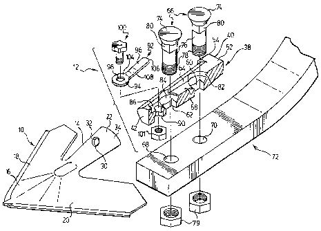
FIG. 1 is a partly exploded perspective view of a retainer according to a
first
preferred embodiment of the invention, shown with an agricultural sweep and
a tine of an- agricultural implement;
FIG. 2 is top plan view of the a retainer of FIG. 1;
FIG. 3 is a top, rear perspective view of the retainer of FIG. 1;
FIG. 4 is a left side elevation view of the retainer of FIG. 1;
FIG. 5 is a rear elevation view of the retainer of FIG. 1;
FIG. 6 is a top plan view of a retainer according to a second preferred
embodiment of the invention;
FIG. 7 is a top, front perspective view of the retainer of FIG. 6;
FIG. 8 is a right side elevation view of the retainer of FIG. 6;
FIG. 9 is a front elevation view of the retainer of FIG. 6;
FIGS. 10 to 12 illustrate steps in the process of mounting an agricultural
sweep as shown in FIG. 1 on the retainer shown in FIG. 1; and
FIG. 13 is a cross-sectional view along line 13-13' of FIG. 12.
CA 02504073 2005-04-13
- 7 -
DETAILED DESCRIPTION OF PREFERRED EMBODIMENTS
Turning now to the drawings, in which similar reference numbers denote
similar elements throughout the several views, FIG. 1 illustrates an
agricultural sweep 10 of the type described in the above-mentioned patents to
Parish and a retainer 12 according to a first preferred embodiment of the
invention.
The sweep 10 preferably has an upwardly-extending tapered stem 14
and an earthworking portion 16 attached to the base of the stem 14. The
earthworking portion 16 comprises a pair of wing elements 18 and 20
integrally formed with the stem 14 and with each other.
Stem 14 has a hollow channel structure with a forwardly-convex front
wall 22 and two rearwardly-directed side walls 24 and 26 (FIG. 13). Side walls
24 and 26 converge toward one another in a rearward direction and, together
with front wall22, define a rearwardly-open space 28 (FIG. 10) which is
adapted to receive the retainer 12 in a wedging friction fit.
Provided on the front wall 22 of stem 14 is an aperture 30 which is
preferably circular in shape, having a circular peripheral edge 32 which is
substantially perpendicular to the front and rear surfaces 34 and 36 (FIG.10)
of the front wall 22.
As illustrated in FIGS. 1 to 3, retainer 12 comprises an elongate,
tapered block of metal 38 (referred to herein as the "adaptor") which is
complementary with the stem 14 of sweep 10 and, in particular, is sized and
shaped to be closely received inside the rearwardly-open space 28 of the stem
14, preferably with a wedging, friction fit. Adaptor 38 has a rear end 40, a
relatively narrower front end 42, a lower surface 44, an opposed upper surface
46 (FIGS. 4 and 5) and a pair of side surfaces 48 and 50 (FIG. 2) connecting
CA 02504073 2005-04-13
r
-
the upper and lower surfaces 46 and 44. A longitudinal axis L (FIG. 2) of
adaptor 38 extends along its length between the front and rear ends 42 and
40. The adaptor 38 has an enlarged rear end portion 52 proximate the rear
end 40. The rear end portion has flat, forwardly-facing surfaces 54 and 56
which project outwardly of the side surfaces 48, 50 and act as stops for the
stem 14 of sweep 10.
Each side surface 48 and 50 of adaptor 38 is multi-faceted and extends
outwardly to a maximum between the upper and lower surfaces 46 and 44
and converge toward one another as they approach the upper surface 46 and
tower surface 44. During mounting of the sweep 10, the outwardly-extending
side surfaces 48 and 50 become wedged against the angled transition between
the front wall 22 and the side walls 24, 26 of the stem 14 as shown in FIG.
13.
As shown in FIG. 1, the upper surface 46 of adaptor 38 is provided with
an elongate, channel-like depression 58. The depression 58 extends along the
axis L between the rear end 40 and front end 42 of adaptor 38. In the
preferred adaptor 38, the depression 58 includes a pair of axially-spaced,
recessed bolt holes 50 and 52 connected by a relatively shallow,
longitudinally-extending rectangular channel 64. Mounting studs 66 are
received in the bolt holes 60 and 62, preferably against rotation. The
mounting studs 66 extend through the lower surface 44 of adaptor 38 and
through holes 68 and 70 of a tine 72 of an agricultural implement. Each stud
has a head 74 and a shank 76 with a with a threaded end portion 78 for
engagement with nuts 79 to secure the retainer 12 to the tine 72. The shank
76 of each stud 66 preferably has an upper portion 80 of square cross section
which is closely received in a square-shaped lower portion of bolt hole 60 ar
62, thereby preventing rotation of stud 66. The square-shaped lower portions
of bolt holes 60 and 62 are not shown in the drawings of the first preferred
retainer 12, but are illustrated in Figures 6 and 7 in connection with the
second preferred embodiment of the invention.
CA 02504073 2005-04-13
_g_
The heads 74 of mounting studs 66 are preferably recessed within
countersinks 82, 84 of bolt holes 60, 62. The countersinks 82, 84 are
preferably provided with upwardly flared conical portions against which the
tapered undersides of heads 74 are retained, and generally cylindrical
portions
which extend upwardly to the upper surface 46 of adaptor 38. In the first
preferred embodiment shown in the drawings, the heads 74 of studs 66 are
countersunk to a depth greater than that of the connecting channel 64.
The channel-like depression 58 in the upper surface 46 of adaptor
further comprises a spring-retaining hole 86 which is located forward of bolt
hole 62 and a short, axially-extending channel through which the hole 86
communicates with bolt hole 62. The spring-retaining hole 86 may preferably
be countersunk to the same depth as the countersunk heads 74 of studs 66.
The spring-retaining hole 86 preferably comprises an upper cylindrical portion
88 having a first diameter and a lower portion 90 of a second, greater
diameter which is multi-faceted so as to receive a nut (not shown) against
rotation. The purpose of spring-retaining hole 86 will be explained in greater
detail below.
The retainer 12 according to the invention further comprises a spring
element 92 which is secured inside the channel-like depression 58 in the upper
surface 46 of the adaptor 38. Spring element 92 comprises an anchoring
portion 94 and a tail portion 96. The anchoring portion 94 which is sized and
shaped to 1=It snugly inside the spring-retaining hole 86 proximate to the
front
end 42 of adaptor 38. In the first preferred embodiment, both the spring-
retaining hole 86 and the anchoring portion 94 are circular, and the anchoring
portion 94 is flat with a bolt hole 98 centrally located therein. As shown in
FIGS. 2 and 3, the anchoring portion 94 is secured inside the spring-retaining
hole 86 by a mounting bolt 100, the threaded shank of which extends through
the upper portion 88 of spring-retaining hole and is threaded into a nut 101
received in the lower portion 90 of spring-retaining hole 86. Preferably, the
CA 02504073 2005-04-13
-10-
spring-retaining hole 86 is countersunk to a sufficient depth that the head of
bolt 100 does not substantially protrude above the upper surface 46 of the
adaptor 38, i.e. does not protrude above upper surface 46 by an amount
greater than the gap 102 (FIGS. 10 to 13) between the adaptor 38 and the
stem 14 of sweep, as shown in FIG. 4. Alternatively, it is preferable that the
bolt 100 is countersunk below the plane of the upper surface 46 of the adaptor
38. It will be appreciated that other fastening means can be employed to
secure the anchoring portion 94 of the spring element 92 to the adaptor 38
including non-threaded fasteners such as rivets.
Securing the anchoring portion 94 of the spring element 92 to the
adaptor 38 prevents substantial longitudinal movement of the spring element
92 relative to the adaptor 38 and the sweep 10 and thereby prevents
accidental release of the sweep 10 from the adaptor 38. Securing the
anchoring portion 94 also prevents accidental release of the spring element 92
from the adaptor 38. This feature facilitates the ease of removing the sweep
10 as there are no loose parts and also prevents the potential loss of parts
in
the field.
The tail portion 96 extends rearwardly from the rear end of anchoring
portion 94. The tail portion 96 has a front end 104 which is connected to the
anchoring portion 94 and a free end 106 spaced rearwardly therefrom along
the axis L. In the preferred embodiment shown in the drawings, the spring
element 92 is integrally formed from a blank of resilient sheet metal,
preferably steel. It is particularly preferred to use a resilient metal such
as
spring steel heated-treated to 40-44 RC.
When the anchoring portion 94 is received and secured within hole 86,
the tail portion 96 extends rearwardly across the front bolt hole 62 and at
least partially across the connecting channel 64. It may also be preferred
that
the tail portion 96 extends at least partially across the rear bolt hole 60,
CA 02504073 2005-04-13
-11-
although in the preferred embodiment shown in the drawings, the tail portion
96 extends only part way along the connecting channel 64.
The tail portion 96 is obtusely angled relative to one anchoring portion
94 and relative to the upper surface 46 of the adaptor 38. The obtuse angle
between the anchoring portion 94 and the tail portion 96 is provided by a
first
bend which is provided at the front end 104 of tail portion 96, and more
precisely at the point where the anchoring portion 94 and the tail portion 96
are connected. The angle of the first bend is sufficient that a portion of the
tai( portion 96 proximate the front end 104 is received in the depression 58
and a portion of the tail portion 96 proximate the free end 106 protrudes out
of depression 58, when the spring element 92 is in its uncompressed state, for
example as shown in FIGS. 4 and 5. The free end 106 protrudes from
depression 58 by an amount which is greater than the gap 102 between the
adaptor 38 and sweep 10 and which is sufficient for engagement of the free
end 106 with aperture 30 of the sweep 10. This will be discussed in greater
detail below.
The tail portion 96 of spring element 92 is sufficiently resilient that it
can be compressed during mounting of retainer 12 to sweep 10. Therefore,
the tail portion 96 is sized, shaped and angled to be compressible within
depression 58. More preferably, the tail portion 96 is shaped and sized to be
closely received inside the depression 58 along at least a portion of its
length,
to thereby prevent the tail portion 96 from pivoting away from the axis L
during use. In the embodiment shown in the drawings, the tail portion is
closely received by the longitudinal edges of connecting channel 64.
Furthermore, the depth of depression 58 is such that the tail portion 96 can
be
substantially completely received inside depression 58 when in its compressed
state.
CA 02504073 2005-04-13
-12-
In the first preferred embodiment of the invention, the tail portion 96 is
not completely flat, but rather is bent very slightly at 108, i.e. between the
front end 104 and the free end 106. This additional bend 108 further ensures
that the maximum height of the free end 106 of tail portion 96 is greater than
the gap 102 between the adaptor 38 and stem 14, when tail portion 96 is
uncompressed. Thus, the free end 106 of tail portion 96 catches in the
aperture 30 of stem 14, preventing accidental dislodgement of the sweep 10.
Preferably, the free end 106 of tail 96 is shaped to conform to the shape of
aperture 30. Since the aperture 30 is circular, the free end 106 is preferably
rounded.
FIGS. 6 to 9 illustrate a second preferred retainer 140 according to the
invention. Details of mounting studs and retaining bolts are omitted from
these drawings for clarity. It will be appreciated that the retainer 140 is
preferably provided with mounting studs and a retaining bolt similar or
identical to studs 66 and retaining bolt 100 described above. The retainer 140
comprises an adaptor 142 in the form of an elongate, tapered block of metal
which is complementary with the stem 14 of sweep 10 as illustrated in FIG.1
and is sized and shaped to be closely received inside the rearwardly-open
space 28 of the stem 14. Adaptor 142 has a rear end 144, a relatively
narrower front end 146, a lower surface 148, an opposed upper surface 150
and a pair of side surfaces 152 and 154 connecting the upper and lower
surfaces 150 and 148. A longitudinal axis L of adaptor 142 extends along its
length between the front and rear ends 144 and 146. The adaptor 142 has an
enlarged rear end portion 156 proximate the rear end 144. The rear end
portion 156 has flat, forwardly-facing surfaces 158 and 160 which project
outwardly of the side surfaces 152, 154 and act as stops for the stem 14 of
sweep 10.
The side surfaces 152 and 154 of adaptor 140 are multi-faceted,
extending outwardly of either side of the planar upper and lower surfaces 148
CA 02504073 2005-04-13
-13-
and 150. During mounting of the sweep 10, the outwardly-extending side
surfaces 152 and 154 become wedged against the angled transition between
the front wall 22 and the side walls 24, 26 of the stem 14.
As shown in FIG. 6, the upper surface 148 of adaptor 142 is provided
with a channel-like depression 162. The depression 162 extends along the
axis L between the rear end 144 and front end 146 of adaptor 142. In the
preferred adaptor 142 illustrated in FIGS. 6 and 7, the depression 162
includes
a pair of axially-spaced, recessed bolt holes 164 and 166 connected by a
shallow channel 168 having a rectangular cross section. Bolt holes 164 and
166 are preferably of a configuration similar or identical to bolt holes 60
and
62 described above and are preferably adapted to retain a pair of studs
against rotation. The connecting channel 168 traverses the adaptor 142
longitudinally between bolt holes 164 and 166. The depression 162 further
comprises a spring-retaining hole 170 which is located forward of bolt hole
166.
The retainer 140 according to the invention further comprises a spring
element 172 which is secured inside the depression 162 in the upper surface
150 of the adaptor 142. Spring element 172 comprises an anchoring portion
174 which is sized and shaped to fit snugly inside the spring-retaining hole
170 proximate to the front end 146 of adaptor 142. The anchoring portion
174 has a centrally located aperture 176 for receiving a retaining bolt
similar
or identical to bolt 100 described above.
The spring element 172 further comprises a tail portion 178 extending
rearwardly from the rear end of anchoring portion 174 (FIG.6). The tail
portion
178 has a front end 180 which is connected to the anchoring portion 174 and
a free end 182 spaced rearwardly therefrom along the axis L.
CA 02504073 2005-04-13
-14-
At least a portion of tail portion 178 is convexly curved. As shown in
the drawings, in a preferred embodiment, the tail portion 178 can be formed
from a steel blank which is shaped to have a central convexly curved portion
184 flanked by planar wings 186 and 188. The convexly curved portion 184
extends to the free end 182 of the tail portion 178 and is sized and shaped to
engage the aperture 30 of sweep 10.
When the anchoring portion 174 is received and secured within
depression 170, the tail portion 178 extends rearwardly across front bolt hole
166 and at least partially across the connecting channel 168. It may also be
preferred that the tail portion 178 extends at least partially across the rear
bolt hole 164, although in the preferred embodiment shown in the drawings,
the tail portion 178 extends only the length of the connecting channel 168.
The tail portion 178 is obtusely angled relative to anchoring portion 174
and relative to the upper surface 150 of the adaptor 142. The obtuse angle
between the anchoring portion 174 and the tail portion 178 is provided by a
bend which is provided at the point where the anchoring portion 174 and the
tail portion 178 meet, i.e. at the front end 180 of the tail portion 178. The
angle is sufficient that a portion of the tail portion 178 proximate the front
end
180 is received in the depression 162 and a portion of the tail portion 178
proximate the free end 182 protrudes out of depression 162, when the spring
element is in its uncompressed state, for example as shown in FIGS. 8 and 9.
The free end 182 protrudes from depression 162 by an amount which is
greater than the gap 102 between the adaptor 142 and sweep 10 and which is
sufficient for engagement of the free end 182 with aperture 30 of the sweep
10.
The tail portion 178 of spring element 172 is sufficiently resilient that it
can be compressed during mounting of retainer 140 to sweep 10. The tail
portion 178 is sized, shaped and angled to be compressible within depression
CA 02504073 2005-04-13
-15-
162. The depth of depression 162 is such that when the spring element 172 is
in its compressed state, the planar wings 186, 188 of the tail portion 178 are
substantially completely received inside depression 162 whereas the convexly
curved portion 184 of the tail portion 178 protrudes out of depression 162 to
engage the underside 36 of the sweep 10. The downward force applied by the
sweep 10 to the convexly curved portion 184 of the tail portion 178 prevents
accidental dislodgement of the sweep 10 from the retainer 140. The
substantially flat longitudinal edges of the planar wings 186, 188 are closely
received by the longitudinal edges of connecting channel 162 to prevent the
tail portion 178 from pivoting away from the axis L during use.
The steps involved in mounting a sweep 10 to the 1=trst preferred
adaptor 12 will now be described with reference to FIGS. 10 to 13. In the
following discussion, it will be assumed that the adaptor 38 is bolted to the
tine 72 of an agricultural implement, as described above, however the tine 72
is not shown in FIGS. 10 to 13. The following discussion is also applicable to
the mounting of a sweep 10 to the second preferred retainer 140.
Firstly, as shown in Figure 10, the stem 14 of sweep 10 is slid
rearwardly in the direction of arrow A over the front end 42. FIG. 11 shows
the front wall 22 of stem 14 having been pushed completely over the tail 96 of
spring element 92. Preferably, the spring element 92 is sufficiently resilient
that the tail portion 96 can be compressed into the depression 58 during
mounting of sweep 10.
When the sweep 10 reaches its normal working position as shown in
FIG. 12, the free end 106 of tail portion 96 enters aperture 30 and springs
back toward its original, uncompressed orientation. At this point the free end
106 catches against the peripheral edge 32 of aperture 30, thus preventing
dislodgement of sweep 10. This can be best seen in FIG. 13. The rearward
CA 02504073 2005-04-13
-16-
mounting of sweep 10 on retainer 12 can be assisted by striking the sweep
with a hammer.
The sweep 10 can be easily dislodged by inserting a tool (not shown)
into aperture 30 to force the free end 106 of tail portion 96 downwardly and
out of engagement with aperture 30. The sweep 10 can then be dislodged
from adaptor 38 by striking the upper edge of stem 14 with a hammer.
Although the retainers according to the invention have been described
as being used for the mounting of sweeps to the tines of agricultural
implements, they are not limited thereto. Rather, the retainers according to
the invention can be used for mounting a variety of earthworking implements,
including sweeps, openers, knives, etc.
Although the invention has been described in connection with certain
preferred embodiments, it is not intended to be limited thereto. Rather, the
invention includes within its scope all embodiments which may fall within the
scope of the following claims.