Note: Descriptions are shown in the official language in which they were submitted.
CA 02504400 2005-04-06
TITLE OF THE INVENTION
CLIP-TYPE SENSOR HAVING
INTEGRATED BIASING AND CUSHIONING MEANS
BACKGROUND OF THE INVENTION
1. Field of the Invention
The present invention generally relates to clip-type sensor devices for use in
measuring a physiological parameter of a patient. More particularly, this
invention
relates to a clip-type sensor device, such as a reusable pulse oximetry (SPOZ)
finger
sensor, having integrated biasing and cushioning means.
2. Background
A common non-invasive medical technique used to monitor blood oxygen
levels is pulse oximetry. This technique takes advantage of the fact that
light
transmissivity and color of blood is a function of the oxygen saturation of
heme in the
blood's hemoglobin. Heme that is saturated with oxygen appears bright red
because
heme is relatively permeable to red light when it is saturated. Heme that is
not
saturated, or deoxygenated, appears dark and bluish as it is less permeable to
red light.
Based on these concepts, a pulse oximeter system measures the oxygen content
of
arterial blood by first illuminating the blood with red and infrared radiation
and
determining the corresponding amounts of red and infrared radiation that are
absorbed
by the heme in the blood. By applying these measurements to other known
information, blood oxygen levels can be determined.
A pulse oximeter typically includes an optical sensor that detects light which
is passed through an appendage of a patient, typically a patient's forger, ear
lobe,
nasal septum or other portion of the body through which light can be easily
transmitted. The amounts of light detected at various wave lengths are then
used to
determine arterial oxygen saturation. The optical sensor is typically in the
form of a
light emitter and a corresponding light detector. The pulse oximeter generally
employs a means for holding the emitter and detector combination relative to
the
patient's body. One common means is a clip, which is employed in a clip-type
sensor. The clip- type sensor typically includes two hingedly connected
housings
onto which the emitter and detector are mounted. The clip-type sensor is
releasably
attached to a patient's appendage so that the appendage is isolated between
the two
CA 02504400 2005-04-06
housings. The emitter, typically a diode, is mounted to one of the housings
and emits
light at a certain wave length through the appendage. The detector is mounted
opposite the emitter to the other housing and detects the amount of light that
is
transmitted through the appendage at various wavelengths.
Although the general concept of a clip-type sensor device is known, there is a
need for improvement in design and construction, especially from the
standpoints of
manufacturability, robustness of design, and overall costs. The present
invention
provides an improved clip-type sensor device that incorporates a resilient
member that
unitarily biases the clamping device and provides a cushion for a patient's
appendage.
Such a device provides the advantages of a more robust design, ease of
manufacturability and reduction in costs associated with manufacture of the
device.
Other advantages will also be apparent from the written specification,
drawings and
claims herein.
SUMMARY OF THE INVENTION
The present invention generally provides a sensor device for non-invasively
measuring a physiological parameter of a patient, such as a pulse oximeter for
measuring blood oxygen levels of a patient. In a preferred embodiment, the
device
comprises a first device portion and a second device portion pivotally
connected to
the first device portion to define a clamping end of the device. A sensing
mechanism
is in communication with the clamping end of the device for sensing at least
one
parameter utilized to determine the blood oxygen level of a patient. A
resilient
member is disposed between the device portions for biasing the device portions
toward each other at the clamping end of the device for clamping an appendage
of the
patient therebetween. The resilient member further provides a cushion for the
appendage at the clamping end of the device.
According to a particular aspect of the invention, the resilient member
comprises.a bias portion distally disposed from the clamping end of the device
and a
cushion portion proximally disposed to the clamping end of the device.
According to another aspect of the invention, the resilient member comprises a
first cushion portion in communication with the first device portion at the
clamping
end of the device; a second cushion portion in communication with the second
device
portion at the clamping end of the device; and a bias portion in communication
with
both device portions proximate the pivotal connection therebetween.
-2-
CA 02504400 2005-04-06
According to yet another aspect, the resilient member comprises an
elastomeric material. The resilient member can be made from a material
selected
from the group consisting essentially of liquid silicon rubber, thermoplastic
elastomers, polyolefin elastomers, thermoplastic rubbers, natural rubbers, and
urethanes.
According to yet another aspect, a resilient member for use with a clip-type
sensor is provided. The member comprises a bias portion that fits between a f
rst
portion and a second portion of the clip-type sensor to bias the portions into
a
clamped position; and a cushion portion integrally formed with the bias
portion that
fits between the first portion and the second portion of the clip-type sensor
to cushion
a finger clamped by the sensor.
In accordance with the principles of the present invention, the resilient
member provides both a biasing means and a cushioning means in a one-piece
configuration, thereby eliminating the need for a separate biasing and
cushioning
means.
Other features and aspects of the invention will be apparent from the written
specification, drawings and claims herein.
BRIEF DESCRIPTION OF THE DRAWINGS
FIG. 1 is a first perspective view of an embodiment of a sensor device in
accordance with the principles of the present invention;
FIG. 2 is a second perspective view of the embodiment of FIG. 1;
FIG. 3 is a side elevational view of the embodiment of FIG. 1; and
FIG. 4 is an end elevational view of the embodiment of FIG. 1.
DETAILED DESCRIPTION OF THE PREFERRED EMBODIMENTS
While this invention is susceptible of embodiment in many different forms,
there is shown in the drawings and will herein be described in detail one or
more
embodiments with the understanding that the present disclosure is to be
considered as
an exemplification of the principles of the invention and is not intended to
limit the
invention to the embodiments illustrated.
Referring to FIGS. 1-4, an embodiment in accordance with the principles of
the present invention is shown in the form of a reusable SP02 forger sensor
device 10.
-3-
CA 02504400 2005-04-06
It is to be understood, however, that the principles of the present invention
may be
applied to any type of clip-type sensor device for use with an appendage of a
patient.
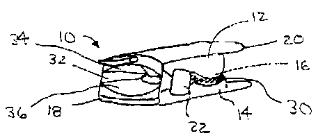
Referring again to FIGS. 1-4, the device 10 comprises a first, or top, portion
12 and a
second, or bottom, portion 14 pivotally connected together at a hingel6 to
define a
clamping end 18 and an actuation end 20 of the device 10. A resilient member
22 is
interposed between the portions 12 and 14 and provides a biasing means
therebetween, which exerts a biasing force against the device portions 12 and
14 and,
in cooperation with the hinge 16, draws the device portions 12 and 14 together
at the
clamping end 18 in a normally closed position.
The sensor device 10 is shown in FIGS. 1-4 in a closed position. To receive a
patient's finger, the device portions 12 and 14 must be drawn together at the
actuation
end 20 of the device 10, against the bias provided by the resilient member 22,
to cause
the device portions 12 and 14 at the clamping end 18 to separate and allow the
patient's finger to be inserted therebetween. Refernng to FIGS. 2 and 4, the
device 10
may include at least one track 26 and at least one pin 28 disposed within the
track 26
to guide movement of the device portions 12 and 14 in relation to each other.
The
track 26 in combination with the pin 28 can provide limits to the extent of
opening
and closing of the device portions 12 and 14.
Refernng again to FIGS. 1-4, it can be seen that the resilient member 22 is a
one-piece member that extends between the top and bottom portions 12 and 14.
In a
preferred embodiment, the resilient member 22 comprises a bias portion 30
distally
disposed from the clamping end 18 of the device 10 and a cushion portion 32
proximally disposed to the clamping end 18 of the device 10. As shown in FIG.
1, the
cushion portion 32 further comprises a first cushion portion 34 and a second
cushion
portion 36 divergently opposed to each other to allow a patient's finger to be
inserted
therebetween. The cushion portions 34 and 36 of the resilient member 22
provide
cushion to the patient's finger when it is clamped thereto. The cushion
portions 34
and 36 also provide a tactile surface that grips a patient's f nger to
facilitate a secure
fit. The first cushion portion 34 is in communication with the first device
portion 12
at the clamping end of the device 10. The second cushion portion 36 is in
communication with the second device portion 14 at the clamping end 18 of the
device 10. In an embodiment, the cushion portions 34 and 36 can be
respectively
secured to the device portions 12 and 14 by any number of means, such as an
adhesive, for example.
-4-
CA 02504400 2005-04-06
As shown in FIGS. 1-3, the bias portion 30 of the resilient member 22 is in
communication with both device portions 12 and 14 proximate the pivotal
connection
therebetween to provide the biasing means between the device portions 12 and
14.
The integral formation of the biasing portion 30 and the cushion portion 32
embodied
S in the resilient member 22 eliminates the need to provide a biasing member,
such as a
spring or clip, separate from a cushioning member. Thus, this one-piece
biasing/cushioning configuration simplifies the design, manufacturability and
assembly of the device 10.
The resilient member 22 may be made from materials such as liquid silicon
rubber, thermoplastic elastomers, polyolefin elastomers, thermoplastic
rubbers,
natural rubbers, and urethanes, or any other material known to those skilled
in the art
that is suitable for providing cushioning properties and that can act as a
biasing
means. The resilient member 22 is preferably made from an elastomeric material
that
provides spring-like elastic properties while also providing a relatively soft
tactile feel
when forced into contact with a patient's finger via the device portions 12
and 14.
The elastomeric material also provides a tactile surface to grip the patient's
finger and
secure the device 10 into place during its use.
The integrated biasing and cushioning aspects of the resilient member 22
facilitates a more robust design, ease of manufacturability, and reduction in
costs
associated with manufacture of the device 10.
While specific embodiments have been illustrated and described, numerous
modifications may come to mind without significantly departing from the spirit
of the
invention, and the scope of protection is only limited by the scope of the
accompanying Claims.
-5-