Note: Descriptions are shown in the official language in which they were submitted.
CA 02505198 2005-04-26
POWER BUS AND STRUCTURE FOR A
BARRIER MOVEMENT OPERATOR
The present invention relates to barrier movement
operators and particularly to apparatus for mounting
barrier movement operators and connecting such operators
to accessories.
Barrier movement operators generally comprise power
and control systems for responding to operator inputs
and sensed conditions to move a barrier between open and
closed positions with respect to an opening. The
barrier may be a door, a gate, a window, a window
shade/protector or similar apparatus. Garage door
operators are a common form of barrier movement
operator. One type of garage door operator comprises a
head end with control circuitry and a motor which
extends and retracts a trolley connected to the door.
The trolley moves along a rail connected between the
head end and a support wall of a garage at a point above
the garage opening. Such a trolley and rail type of
garage door operator is generally supported from an
overhead structure such as the ceiling joists of a
garage. Support is often achieved by vertical metal
support members from the housing of the head end to the
ceiling joists which may result in a less than stylish
connection. Further, it may be desirable to provide
ancillary equipment or accessories to improve the
functionality of the garage in which the garage door
operator is mounted. For example, it may be desirable
to place additional lighting in the garage, which in
some instances, may be controlled by the controller of
the head end. Also, it may be desirable in the garage
to provide a readily available extension cord and/or a
-1-
CA 02505198 2011-12-09
mechanic's light and the garage door operator itself may
gain advantage to having an attached security camera,
monitor, motion sensor and other sensing equipment. At
present, the inclusion of such additional equipment results
in a confused mix of non-similar items affixed throughout
the garage. The present system envisions an improved
system for supporting a barrier movement operator and
providing ancillary equipment.
Summary of the Invention
In accordance with one aspect of the present
invention, there is provided a support apparatus for
overhead mounting of a barrier movement operator having a
width, the barrier movement operator including a
controller, the support apparatus comprising: a semi rigid
elongate member having a length greater than the width of
the barrier movement operator; a plurality of upper
supports connected to the elongate member for attaching the
elongate member to an overhead structure and suspending the
elongate member from the overhead structure so as to be
separate from the overhead structure, the elongate member
being substantially rigidly connected to the overhead
structure in a substantially horizontal plane; connection
apparatus for connecting the elongate member to the barrier
movement operator; a plurality of electrically powered
accessories supported by the elongate member; a power
distribution system responsive to the controller for
distributing electrical power to the electrically powered
accessories; and an apparatus for removably connecting the
power distribution system to a mains voltage source;
wherein the barrier movement operator provides electrical
power to the power distribution system.
-2-
CA 02505198 2011-12-09
Brief Description of the Drawings
Fig. 1 is a perspective view of a mounted prior art
barrier movement operator;
Fig. 2 is a perspective view of an improved barrier
movement operator mounting;
Fig. 3 is a front plan view of the mounting of Fig. 2;
Fig. 4 is an end view of an elongate member and
vertical support used in Fig. 2;
Fig. 5 is an electrical block diagram illustrating
power distribution; and
Fig. 6 is a top view of the barrier movement operator.
-2a-
CA 02505198 2005-04-26
Description
Fig. 1 is a perspective view of the inside of a
secure area such as a garage, having a known barrier
movement operator. The area has a ceiling 16 and a
front wall 14 with a doorway (not shown) therethrough
which is opened and closed by a paneled garage door 24.
The position of the door 24 is controlled by a barrier
movement operator head end 12 which moves a trolley 20
out and back along a rail 18. The trolley 20 is
connected to door 24 by a trolley/door arm 22. The door
24 includes rollers at its edges which engage doorguides
26 and 28 and as the trolley 20 is drawn toward the head
end 12 the door 24 is raised in the doorguides to a
substantially horizontal position. The movement-of the
door may be controlled by user interaction with a wall
control unit 31 which signals the head end of the user's
requests. The head end 12, which includes an electric
motor, is powered from a mains voltage outlet 15 and is
supported from the joists of the ceiling by support
members 13. Other sensors and signaling devices may be
used to control barrier movement, but are not described
because they are not necessary for an understanding of
the present invention.
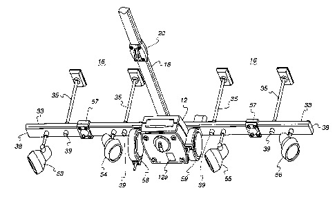
Fig. 2 is an upward perspective view of a combined
barrier movement operator support and power busing
system. The trolley of the Fig. 2 arrangement may be
connected to a trolley/door arm 22 as shown in Fig. 1 to
raise and lower a door or other barrier. Fig. 3 is a
view of the same structure as Fig. 2, but the view is
from the front of the garage, along the trolley rail 18.
The structure of Fig. 2 includes an elongate member 33
which is supported by a plurality of vertical members 35
from an over head structure. The over head structure
-3-
CA 02505198 2005-04-26
may be ceiling joists or another support member secured
to the overhead structure of the garage. Elongate
member 33, which is shown in cross section in Fig. 4,
comprises an open trough 34 which may be fabricating by
roll forming 16 gauge sheet steel. The open trough 34
runs the length of the elongate member and may be used
to provide power to accessories attached to the elongate
member as discussed below.
Vertical members 35 may comprise hollow tubes
having a shoulder portion 37 at a bottom thereof.
Shoulder portion is affixed to the hollow tube vertical
member 35 and includes female threads at the open end
thereof. The elongate member 33 includes a plurality of
mounting holes and the vertical members 35 are connected
to the elongate member 33 by bolts 39 screwed into the
female inner threads of shoulders 37 through the holes.
The open ends of elongate member 33 may be closed by end
caps 38.
Fig. 6 is a top plan view of the barrier movement
operator 12 portion of the elongate member 33 and
portion of the trolley rail 18. The barrier movement
operator 12 is secured to the elongate member 33 by
means of a plurality of bolts 41 which extend through
the elongate member 33 into threaded holes in the
barrier movement operator. Similarly, the trolley rail
18 is secured to the top of barrier movement operator 12
by means of a pair of bolts 43 through the rail and into
barrier movement operator, Also shown in Fig. 6 is a
drive sprocket 45 which is rotated by a motor (not
shown) to move a chain 47 which is attached to trolley
20. Mains voltage may be provided to the barrier
movement operator by a multi conductor power wire 49
which passed through one of the hollow vertical supports
and into the hollow trough 34 of elongate member 33.
35 Power wire 49 runs along the interior 34 of elongate
-4-
CA 02505198 2005-04-26
member 33 and is passed to the barrier movement operator
12 via an opening 51 in the elongate member.
The elongate member 33 also includes a number of
points at which accessories can be attached to provide
additional functionality. As shown in Fig. 3, light
fixtures 53 and 54 are attached to a portion of the
elongate member 33 to the left of the barrier movement
operator 12 and light fixtures 55 and 56 are attached to
the right. Further, a retractable cord, mechanic's
light 58 is attached to the elongate member as is a
retractable hose reel 59 for supplying compressed air
from a compressor 52. In other embodiments, other
accessories such as a battery charger, security camera,
CO monitor, motion detector etc., may be attached to the
elongate member 33.
Fig. 5 is an electrical block diagram illustrating
the connection and distribution of electrical power
using the arrangement of Fig. 2. In Fig. 5 a portion of
the elongate member 33 is shown to represent it's power
distribution or power bus function and barrier movement
operator 12 is shown in block diagram form. Barrier
movement operator 12 comprises power distribution
apparatus 71, a controller 73, barrier movement
apparatus 75 and a light assembly 77. Barrier movement
apparatus 75 may include a motor and sensors (not shown)
which cooperate with control unit 73 to open and close a
barrier. Power distribution unit 71 is equipped to
receive mains voltage and to distribute mains voltage,
or another created voltage, under the control of
controller 73. The light 77 is a common part of barrier
movement operators and is used to provide one source of
illumination under the control of controller 73.
Power wire 49 is connectable to a source of mains
voltage and connects that voltage to power distribution
unit 71. Power distribution unit 71 distributes power
within barrier movement operator 12 as is needed to
-5-
CA 02505198 2005-04-26
provide barrier movement. Controller 73 is also
responsible for controlling the application of mains
voltage and other electrical power derived therefrom to
accessories connected to barrier movement operator 12.
The following are examples of power distribution
via elongate member 33. The mains power on power
conductor 49 may be distributed directly to attached
accessories on elongate member 33 by connection to the
power conductor. For example, one accessory may be a
"night light" which is continuously powered, but which
senses light levels and turns on the "night light" when
light levels drop below a predetermined level. Further,
the mechanics' light and cord reel 58 and the compressor
52 may be permanently supplied with mains power by
connection to power conductor 49. A battery charger 61
may also be permanently connected to mains power. AC
mains power may be selectively provided to accessories
by the power distribution unit 71 under the control of
controller 73. For example, when a left hand garage
door is being opened lights 54 and 53 may receive mains
power from power distribution 71 via conductor 77.
Similarly, lights 55 and 56 may receive mains power from
power distribution unit 71 via conductor 79 when a right
hand garage door is being opened. Further, laser
positioning devices 57 may receive power via conductor
81 or 82 to create a light spot only briefly when a
vehicle is entering one side or the other of the garage.
The power sent to a laser light 57 may be AC mains or DC
created by power distribution 71 under control of
controller 73. In addition, conductors 91 may be
employed by power distribution 71 to distribute low
voltage power along elongate member 33.
In the preceding embodiments, elongate member is
shown as being open at the top. The elongate member may
be closed on its top to provide protection against
improper contact with household voltage. The barrier
-6-
CA 02505198 2005-04-26
movement operator is shown in the preceding, attached to
the underside of the elongate member. In other
embodiments, the barrier movement operator may be
attached to the top of the elongate member and rest
thereon. Mains power was supplied to the apparatus by a
power cord 49 passing through a hollow vertical support
35. In other embodiments, the power cord may be
connected to mains power without passing through a
vertical support and such power may be supplied directly
to barrier movement operator 12 via a power cord as
shown in Fig. 1.
While there has been illustrated and described
particular embodiments of the present invention, it will
be appreciated that numerous changes and modifications
will occur to those skilled in the art, and it is
intended in the appended claims to cover all those
changes and modifications which fall within the true
scope of the present invention.
-7-