Language selection

Search

Patent 2505564 Summary

Third-party information liability

Some of the information on this Web page has been provided by external sources. The Government of Canada is not responsible for the accuracy, reliability or currency of the information supplied by external sources. Users wishing to rely upon this information should consult directly with the source of the information. Content provided by external sources is not subject to official languages, privacy and accessibility requirements.

Claims and Abstract availability

Any discrepancies in the text and image of the Claims and Abstract are due to differing posting times. Text of the Claims and Abstract are posted:

  • At the time the application is open to public inspection;
  • At the time of issue of the patent (grant).
(12) Patent Application: (11) CA 2505564
(54) English Title: SPEED SENSITIVE ROTATIONAL DRIVE STEERABLE DRILLING SYSTEM
(54) French Title: SYSTEME DE FORAGE ORIENTABLE A ENTRAINEMENT ROTATIF SENSIBLE A LA VITESSE
Status: Deemed Abandoned and Beyond the Period of Reinstatement - Pending Response to Notice of Disregarded Communication
Bibliographic Data
Abstracts

English Abstract


The following is a proposal for a new steerable drill design for the oil and
gas
industry.
The design relies on variations in the rotational speed of the drill pipe
(also called
the drill string) controlled from the surface to steer the drill bit in the
desired
direction. The steering is accomplished by a hydraulic-mechanical system
consisting of a hydraulic pump, a speed sensing device, coupled to a selector
valve, which controls the angle of deflection of the bit and the direction of
the
deflection through 360 degrees.
The device will also be able to drill in a straight line by eliminating the
offset of
the bit to zero degrees as the rotational speed of the drill string is
increased
beyond the directional drilling speed range.
Rotation of the internal mechanism of the device, along with the rotation of
the
drill string will be prevented by an anti rotational device, consisting of a
gravity
sensing valve, hydraulic motor and wellbore tracking wheels. The device is
fully
hydro-mechanical in nature and does not incorporate mud motors or electronics
of any kind and is capable being used with standard oil field drilling rigs,
drill pipe
and drill bits.


Claims

Note: Claims are shown in the official language in which they were submitted.
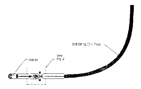

Speed Sensitive Rotational Drive Steerable Drill System.
Claims:
1 ) The proposed device is fully steerable while maintaining
rotational drive for the drill bit, without the need for a mud
motor or electronic directional controls, using variation in
rotational velocity (RPM) of the drill string, controlled from
the surface.
2) The proposed system will not require any specialized
equipment to run it. It can be operated using standard oilfield
drilling rigs, drill pipe and drill bits.
3) The proposed system allows for true straight drilling without
the need to rotate the whole directional control system and
the resulting enlarged hole size. It accomplishes this by
reducing the offset angle to zero when the drill string
rotational velocity is increased above a preset value.
4) The proposed system will allow full drilling fluid pressure to
be used for the clearing of cuttings from the well bore as well
as allow for the continually rotating drill string to further aid in
clearing of the cuttings and reducing the possibility of the
assembly becoming stuck in the wellbore.
5) The control mechanism of the device is held in the proper
position relative to vertical using a hydro mechanical system
incorporated in the design.
1

Description

Note: Descriptions are shown in the official language in which they were submitted.


CA 02505564 2005-04-04
Speed Sensitive Rotational Drive Steerable Drill System.
Detailed Description
The speed sensitive rotational drive steerable drill system provides a
method for steering a drill bit underground through the use of changes in
the rotational speed of the drill pipe.
Previous designs for steerable drill technology have relied on a fixed offset
angle of the drill bit and a mud motor used to drive the bit while the
direction is controlled by the orientation of the drill pipe in the wellbore.
The drill pipe cannot be rotated continuously during directional drilling.
Only during straight drilling is the Drill pipe rotated and with it the entire
directional drill assembly. Some designs have been produced where the
directional control is electronic in nature and a mud motor is still used to
drive the drill bit.
In this proposed design, there is no need for a mud motor to drive the drill
bit as the drill shaft performs this function, in the same manner it would in
a conventional non-steerable drill system. The drill pipe does not need to
be stopped in order for directional drilling to take place as it is in most
other directional drill systems. In fact the rotation of the drill pipe is
crucial
to the operation of the device.
The absence of a mud motor in the design means that the full pressure of
the drill fluid can be utilized to clear the drill bit of drill cuttings and
to
transport the cuttings through the wellbore, aided further by the rotation of
the drill pipe in the wellbore.

CA 02505564 2005-04-04
2
The angle of the drill bit shaft to the drill shaft will be referred to as the
offset angle. The angle that the offset points to relative to vertical will be
referred to as the drill bit direction angle.
The directional angle of the drill bit is determined by the rotational speed
of the drillpipe. In this manner the drilling direction can be controlled from
the surface by means of varying the rotational speed of the drill pipe. If no
deviation is required from the bit and straight drilling is desired, the
rotational speed can be increased above a preset value, causing the
steering unit to go from full offset to zero offset. This will enable the
drilling
of a true, straight wellbore of the same dimension as the drill bit.
The steering control for the drill operates as follows: (Refer to Fig. 2 for
numbered references)
The rotational input of the drill pipe is fed directly through the unit by the
drill shaft (5) to the drill bit . The drill shaft has a universal joint
incorporated in it, inside the pivot (11 ) . Hydraulic fluid is stored in the
bottom half of the body from where it feeds the hydraulic pump through a
feed pipe. (17) Return fluid runs back to the bottom of the body by gravity.
Power for the hydraulic pump (8) and the speed sensor (4) are taken from
the drill shaft via the beveled gears (12). The flyweights of the speed
sensor (4) are forced outward by centrifugal force as the speed of the drill
shaft is increased. This in turn compresses the speeder spring (14) and
moves the summing lever (15) upwards. The summing lever in turn moves
the selector valve spool (3) which ports hydraulic pressure from the pump
to the angle input motor (13) which drives the body (18) of the device to a
new position by driving the ring gear (2), thereby changing the direction
angle of the drill bit. As the body turns, the feedback cam (6) increases the

CA 02505564 2005-04-04
3
force on the speeder spring which in turn forces the flyweights back to
their original position, returning the system to equilibrium. The drill is now
set to a new direction angle relative to vertical, corresponding to the
rotational speed input.
If the speed of the drill shaft is reduced, the same sequence will occur but
in the opposite direction, resulting in a drill bit direction angle change in
the opposite direction. Therefore there will be a specific drill shaft speed
corresponding to each and every drill bit direction angle through 360
degrees , at which the body cannot rotate any further.
The offset angle of the drill bit can be reduced to zero by increasing the
drill shaft speed beyond the speed range set for the range of bit direction
angles. When the maximum movement of body rotation is reached, the
feedback cam is no longer able to re-center the flyweights. As speed is
increased further, the flyweights will move out further, causing the selector
valve spool to move beyond it's previous operating range. This ports
pressure to the offset actuator (7), which moves the pivot (11) to zero
offset angle. The unit will now drill in a straight line.
The direction of the drilling operation is controlled from the surface by
changing the speed of the drilling rig's rotational drive. The directional
unit
will be calibrated before drilling and the speeds required for left, right ,up
and down turns noted as well as the speed above which the bit will drill in
a straight line.

CA 02505564 2005-04-04
4
It is important, in order for the device to work properly that the internal
mechanism (16) is always maintained in the proper orientation relative to
vertical. The mechanism should not be allowed to rotate with the drill
shaft. This is accomplished by the anti-rotational assembly (1) The Gravity
sensing valve (9) incorporates a pendulum which , when deviated from
vertical causes this valve to port hydraulic pressure to the anti rotational
motor (10) which in turn causes rotational movement of the anti-rotational
assembly (1) in the opposite direction of the deviation. The wheels of the
anti rotational assembly track along the wellbore through the use of spring
loaded arms (19) and provide a resistance to rotational movement of the
assembly, relative to the wellbore. This results in the rotation of the
internal mechanism back to the proper position relative to vertical.

Representative Drawing
A single figure which represents the drawing illustrating the invention.
Administrative Status

2024-08-01:As part of the Next Generation Patents (NGP) transition, the Canadian Patents Database (CPD) now contains a more detailed Event History, which replicates the Event Log of our new back-office solution.

Please note that "Inactive:" events refers to events no longer in use in our new back-office solution.

For a clearer understanding of the status of the application/patent presented on this page, the site Disclaimer , as well as the definitions for Patent , Event History , Maintenance Fee  and Payment History  should be consulted.

Event History

Description Date
Application Not Reinstated by Deadline 2010-04-06
Time Limit for Reversal Expired 2010-04-06
Inactive: Adhoc Request Documented 2010-01-07
Inactive: Office letter 2009-06-16
Letter Sent 2009-06-10
Request for Examination Received 2009-04-24
Request for Examination Requirements Determined Compliant 2009-04-24
All Requirements for Examination Determined Compliant 2009-04-24
Deemed Abandoned - Failure to Respond to Maintenance Fee Notice 2009-04-06
Letter Sent 2008-11-10
Reinstatement Requirements Deemed Compliant for All Abandonment Reasons 2008-10-23
Deemed Abandoned - Failure to Respond to Maintenance Fee Notice 2008-04-04
Application Published (Open to Public Inspection) 2006-10-04
Inactive: Cover page published 2006-10-03
Inactive: First IPC assigned 2005-06-15
Inactive: IPC assigned 2005-06-15
Application Received - Regular National 2005-05-31
Inactive: Office letter 2005-05-31
Inactive: Filing certificate - No RFE (English) 2005-05-31
Small Entity Declaration Determined Compliant 2005-04-04

Abandonment History

Abandonment Date Reason Reinstatement Date
2009-04-06
2008-04-04

Maintenance Fee

The last payment was received on 2008-10-23

Note : If the full payment has not been received on or before the date indicated, a further fee may be required which may be one of the following

  • the reinstatement fee;
  • the late payment fee; or
  • additional fee to reverse deemed expiry.

Patent fees are adjusted on the 1st of January every year. The amounts above are the current amounts if received by December 31 of the current year.
Please refer to the CIPO Patent Fees web page to see all current fee amounts.

Fee History

Fee Type Anniversary Year Due Date Paid Date
Application fee - small 2005-04-04
MF (application, 2nd anniv.) - small 02 2007-04-04 2007-01-23
MF (application, 3rd anniv.) - small 03 2008-04-04 2008-10-23
Reinstatement 2008-10-23
Request for examination - small 2009-04-24
Owners on Record

Note: Records showing the ownership history in alphabetical order.

Current Owners on Record
JACOBUS HENDRIK VISSER
Past Owners on Record
None
Past Owners that do not appear in the "Owners on Record" listing will appear in other documentation within the application.
Documents

To view selected files, please enter reCAPTCHA code :


To view images, click a link in the Document Description column. To download the documents, select one or more checkboxes in the first column and then click the "Download Selected in PDF format (Zip Archive)" or the "Download Selected as Single PDF" button.

List of published and non-published patent-specific documents on the CPD .

If you have any difficulty accessing content, you can call the Client Service Centre at 1-866-997-1936 or send them an e-mail at CIPO Client Service Centre.


Document
Description 
Date
(yyyy-mm-dd) 
Number of pages   Size of Image (KB) 
Drawings 2005-04-03 2 257
Description 2005-04-03 4 131
Claims 2005-04-03 1 29
Abstract 2005-04-03 1 29
Representative drawing 2006-01-23 1 20
Filing Certificate (English) 2005-05-30 1 157
Notice: Maintenance Fee Reminder 2007-01-07 1 126
Notice: Maintenance Fee Reminder 2008-01-06 1 121
Courtesy - Abandonment Letter (Maintenance Fee) 2008-06-01 1 173
Second Notice: Maintenance Fee Reminder 2008-10-06 1 118
Notice of Reinstatement 2008-11-09 1 164
Notice: Maintenance Fee Reminder 2009-01-05 1 121
Courtesy - Abandonment Letter (Maintenance Fee) 2009-05-31 1 172
Acknowledgement of Request for Examination 2009-06-09 1 174
Second Notice: Maintenance Fee Reminder 2009-10-05 1 118
Notice: Maintenance Fee Reminder 2010-01-04 1 128
Correspondence 2005-05-30 1 13
Fees 2007-01-22 1 49
Fees 2008-10-22 2 31
Fees 2009-04-23 1 13
Correspondence 2009-06-15 1 20