Note: Descriptions are shown in the official language in which they were submitted.
CA 02505565 2005-04-28
CWC - 248
-1-
APPARATUS AND METHOD FOR CONTROLLING A CLOTHES DRYER
Field of the Invention
The present invention relates to an appliance for drying clothing
articles, and more particularly, to a dryer using microprocessor based
controls
for controlling dryer operation.
Background of the Invention
It is common practice to detect the moisture level of clothes tumbling in
a dryer by the use of sensors located in the dryer drum. A voltage signal from
the moisture sensor is used to estimate the moisture content of the articles
being dried based on the actual characteristics of the load being dried. The
sensors are periodically sampled to provide raw voltage values that are then
filtered or smoothed, and inputted to a processor module that determines
when the clothes are dry, near dry, or at a target level of moisture content,
and the drying cycle should terminate.
The filtered voltage is typically compared with a target voltage stored in
memory associated with the microprocessor. This target voltage is a
predetermined voltage determined for the dryer. Once the target voltage is
reached, this is an indication to the dryer that a predetermined degree of
dryness for the load has been reached. The microprocessor controls the
drying cycle and/or cool down cycle of the dryer in accordance with preset
user conditions and the degree of dryness of the load in the dryer relative to
the target voltage.
CA 02505565 2005-04-28
CWC -248
The target voltage is chosen for a predetermined or average load size
and a preset air flow rate for the dryer. This target voltage may not
accurately
reflect different load sizes and differing air flow conditions for the dryer
resulting in the automatic drying cycle either drying the clothing too long or
insufficiently.
For example, the smaller the load the higher the target voltage should
be set because larger loads are in contact with the sensors more frequently
and this reduces the value of the filtered voltage signal.
Also, the air flow influences the level of the smoothed or filtered
voltage signal. The greater the air flow through the dryer the more clothes
are
pulled towards the front of the dryer increasing the frequency of contact of
the
clothing with the moisture sensor when the moisture sensor is mounted at the
front of the dryer drum.
Accordingly, there is a need for a drying algorithm that sets its target
voltage associated with the moisture content of the clothes and which takes
into consideration the influences associated with load size and/or air flow
condition.
Brief Description of the Invention
The present invention relates to a clothes dryer having a degree of
dryness control system or processor responsive to the moisture level of
clothing articles tumbling in a drum and a target moisture value to control
the
drying cycle of the clothes dryer. The clothes dryer comprises one or both of
a load size parameter generating module and an air flow parameter
generating module. Each of these modules may generate one of two
parameter conditions to be used separately or in combination by the
processor to modify or select a more appropriate target moisture value to be
utilized by the degree of dryness control system. It is envisaged that each
module may generate more than two parameter conditions if sufficient
memory is available.
In one embodiment, the load size parameter generating module
generates one of a small load input parameter and a large load input
parameter to be utilized by the degree of dryness processor. In another
-2-
CA 02505565 2005-04-28
CWC -248
embodiment, the air flow generating module produces one of a first and
second air flow parameter to be utilized by the degree of dryness processor.
In yet another embodiment, both these modules are utilized to each generate
two conditions. As a result, the processor selects one of four target moisture
values from these conditions.
In an embodiment, the air flow generating module is coupled to an inlet
temperature sensor to sense inlet temperature of heated air entering into the
drum. This module measures a first slope corresponding to the rise of the
inlet temperature of air entering the drum during a first initial time period
of
operation of the dryer and compares the first slope with a first value
indicative
of a first predetermined slope for rise of the inlet temperature during the
first
initial period. This module generates and transmits to the processor one of a
first air flow input parameter or a second air flow input parameter each of
which is indicative of a different air flow condition in the dryer. The first
air
flow parameter is generated when this module determines that the first slope
is less than the first value. The second air flow input parameter is generated
when this module determines that the first slope is greater than the first
value.
It should be understood that the air flow parameter corresponds to air
flow through the dryer drum and is usually dependent upon the length of
exhaust venting from the dryer to atmosphere. Poor air flow through the drum
and exhaust venting relates to a relatively longer venting and dirty exhaust
while good air flow through the drum and exhaust venting relates to a shorter
venting and clean exhaust. In a preferred aspect of the present invention, the
air flow parameter is measured as a function of the air flow restriction or
blockage of air flow through the dryer which is inversely proportional to the
rate of air flow through the dryer. Accordingly, the term air flow parameter
is
used herein to include one of either an air flow restriction or an air flow
rate.
In another embodiment the load size parameter generating module is
coupled to the outlet temperature sensor to sense outlet temperature of air
exiting from the drum. This module measures a second slope corresponding
to the rise of the outlet temperature of air exiting from the drum during a
second initial time period of operation of the dryer, compares the second
-3-
CA 02505565 2005-04-28
CWC -248
slope with a second value indicative of a second predetermined slope for rise
of the outlet temperature during the second initial period, and generates and
transmits to the processor one of a small load input parameter and a large
load input parameter. The small load input parameter is generated when this
module determines that the second slope is greater than the second value.
The large load input parameter is generated when this module determines
that the second slope is less than the second value.
In one embodiment of the invention there is provided an appliance for
drying clothing articles. The appliance comprises a drum for receiving the
clothing articles, a motor for rotating the drum about an axis, a heater for
supplying heated air to the drum during a drying cycle, a moisture sensor for
providing a moisture signal indicative of the moisture content of the clothing
articles, an inlet temperature sensor for sensing temperature of the heated
air
flowing into the drum, a processor, and a first parameter generating module.
The processor is coupled to the moisture sensor for estimating the stop time
of the dry cycle as the dry cycle is executed based on a signal representative
of the moisture content of the clothing articles and a selected target signal.
The processor selects the selected target signal based on at least one input
parameter received from the first parameter generating module. The first
parameter generating module is coupled to the inlet temperature sensor to
sense inlet temperature of heated air entering into the drum. The first
parameter generating module measures a first slope corresponding to the rise
of the inlet temperature of air entering the drum during a first initial time
period of operation of the dryer and compares the first slope with a first
value
indicative of a first predetermined slope for rise of the inlet temperature
during
the first initial period. The first parameter generating module generates and
transmits to the processor one of a first air flow input parameter or a second
air flow input parameter. The first air flow input parameter is generated when
the first parameter generating module determines that the first slope is less
than the first value. The second air flow input parameter is generated when
the first parameter generating module determines that the first slope is
greater than the first value.
-4-
CA 02505565 2005-04-28
CWC -248
In accordance with another embodiment there is provided an appliance
for drying clothing articles. The appliance comprises a drum for receiving the
clothing articles, a motor for rotating the drum about an axis, a heater for
supplying heated air to the drum during a drying cycle, a moisture sensor for
providing a moisture signal indicative of the moisture content of the clothing
articles, an outlet temperature sensor for sensing temperature of air exiting
from the drum, a processor and a second parameter generating module. The
processor is coupled to the moisture sensor for estimating the stop time of
the
dry cycle as the dry cycle is executed based on a signal representative of the
moisture content of the clothing articles and a selected target signal. The
processor selects the selected target signal based on at least one input
parameter received from the second parameter generating module. The
second parameter generating module is coupled to the outlet temperature
sensor to sense outlet temperature of air exiting from the drum. The second
parameter generating module measures a second slope corresponding to the
rise of the outlet temperature of air exiting from the drum during a second
initial time period of operation of the dryer, compares the second slope with
a
second value indicative of a second predetermined slope for rise of the outlet
temperature during the second initial period, and generates and transmits to
the processor one of a small load input parameter and a large load input
parameter. The small load input parameter is generated when the second
parameter generating module determines that the second slope is greater
than the second value. The large load input parameter is generated when the
second parameter generating module determines that the second slope is
less than the second value.
In another embodiment both the first and second parameter generating
modules are present in the clothes dryer. It is envisaged that the processor
has a look up table of target moisture values and selects one of the target
moisture values based on the generated load size parameter and air flow
parameter.
The invention provides a method for modifying a degree of dryness
control system for a clothes dryer that controls the drying of clothing
articles
-5-
CA 02505565 2005-04-28
CWC -248
tumbling in a drum in accordance with a target moisture value. The method
comprises generating an input parameter and modifying the target moisture
value based on the generated input parameter. The generating of the input
parameter comprises the steps of:
sensing inlet temperature of air entering into the drum;
measuring a first slope corresponding to rise of the inlet temperature
during a first initial time period of operation of the dryer;
comparing the first slope with a first value indicative of a first
predetermined slope representative of a predetermined inlet temperature rise;
generating a first air flow input parameter for use by the degree of
dryness control system when the first slope is less than the first value; and,
generating a second air flow input parameter for use by the degree of
dryness control system when the first slope is greater than the first value.
The invention also provides a method for modifying a degree of
dryness control system for a clothes dryer that controls the drying of
clothing
articles tumbling in a drum in accordance with a target moisture value. The
method comprises generating an input parameter and modifying the target
moisture value based on the generated input parameter. The generating of
the input parameter comprises the steps of:
sensing outlet temperature of air exiting from the drum;
measuring a second slope corresponding to rise of the outlet
temperature during a second initial time period of operation of the dryer;
comparing the second slope with a second value indicative of a second
predetermined siope representative of a predetermined outlet temperature
rise;
generating a small load input parameter for use by the degree of
dryness control system when the second slope is greater than the second
value; and,
generating a large load input parameter for use by the degree of
dryness control system when the second slope is less than the second value.
-6-
CA 02505565 2005-04-28
CWC -248
Brief Description of the Drawings
For a better understanding of the nature and objects of the present
invention reference may be had by way of example to the accompanying
diagrammatic drawings.
Figure 1 is a perspective view of an exemplary clothes dryer that may
benefit from the present invention;
Figure 2 is a block diagram of a controller system used in the present
invention;
Figure 3 is a block diagram showing the processor and parameter
generating modules of the present invention;
Figure 4 is a table showing selection criteria for the target moisture
value;
Figure 5 is a plot of inlet temperature rise vs. time for different air flow
restrictions;
Figure 6 is an exemplary flow chart for generating an air flow input
parameter in accordance with the present invention;
Figure 7 is a plot of outlet temperature rise vs. time for different load
sizes;
Figure 8 is an exemplary flow chart for generating a first load size input
signal in accordance with the present invention; and
Figure 9 is an exemplary flow chart for generating a second load size
input signal in accordance with the present invention.
Detailed Description of the Invention
Figure 1 shows a perspective view of an exemplary clothes dryer 10
that may benefit from the present invention. The clothes dryer includes a
cabinet or a main housing 12 having a front panel 14, a rear panel 16, a pair
of side panels 18 and 20 spaced apart from each other by the front and rear
panels, and a top cover 24. Within the housing 12 is a drum or container 26
mounted for rotation around a substantially horizontal axis. A motor 44
rotates the drum 26 about the horizontal axis through, for example, a pulley
43 and a belt 45. The drum 26 is generally cylindrical in shape, has an
-7-
CA 02505565 2005-04-28
CWC -248
imperforate outer cylindrical wall 28, and is closed at its front by a wall 30
defining an opening 32 into the drum 26. Clothing articles and other fabrics
are loaded into the drum 26 through the opening 32. A plurality of tumbling
ribs (not shown) are provided within the drum 26 to lift the articles and then
allow them to tumble back to the bottom of the drum as the drum rotates.
The drum 26 includes a rear wall 34 rotatably supported within the main
housing 12 by a suitable fixed bearing. The rear wall 34 includes a plurality
of
holes 36 that receive hot air that has been heated by a heater such as a
combustion chamber 38 and a rear duct 40. The combustion chamber 38
receives ambient air via an inlet 42. Although the exemplary clothes dryer 10
shown in Figure 1 is a gas dryer, it could just as well be an electric dryer
having electric resistance heater elements located in a heating chamber
positioned adjacent the imperforate outer cylindrical wall 28 which would
replace the combustion chamber 38 and the rear duct 40. The heated air is
drawn from the drum 26 by a blower fan 48 which is also driven by the motor
44. The air passes through a screen filter 46 which traps any lint particles.
As
the air passes through the screen filter 46, it enters a trap duct seal 48 and
is
passed out of the clothes dryer through an exhaust duct 50. After the clothing
articles have been dried, they are removed from the drum 26 via the opening
32.
In one exemplary embodiment of this invention, a moisture sensor 52
is used to predict the percentage of moisture content or degree of dryness of
the clothing articles in the container. Moisture sensor 52 typically comprises
a
pair of spaced-apart rods or electrodes and further comprises circuitry for
providing a voltage signal representation of the moisture content of the
articles to a controller 58 based on the electrical or ohmic resistance of the
articles. The moisture sensor 52 is located on the front interior wall of the
drum and alternatively have been mounted on the rear drum wall when this
wall is stationary. In some instances the moisture sensor has been used on a
baffle contained in the dryer drum. By way of example and not of limitation,
the sensor signal may be chosen to provide a continuous representation of
the moisture content of the articles in a range suitable for processing by
-8-
CA 02505565 2005-04-28
CWC -248
controller 58. It will be appreciated that the signal indicative of the
moisture
content need not be a voltage signal being that, for example, through the use
of a voltage-controlled oscillator, the signal moisture indication could have
been chosen as a signal having a frequency that varies proportional to the
moisture content of the articles in lieu of a signal whose voltage level
varies
proportional to the moisture content of the articles.
As the clothes are tumbled in the dryer drum 26 they randomly contact
the spaced-apart electrodes of stationary moisture sensor 52. Hence, the
clothes are intermittently in contact with the sensor electrodes. The duration
of contact between the clothes and the sensor electrodes is dependent upon
several factors, such as drum rotational speed, the type of clothes, the
amount or volume of clothes in the drum, and the air flow through the drum.
When wet clothes are in the dryer drum and in contact with the sensor
electrodes, the resistance across the sensor is low. Conversely, when the
clothes are dry and contacting the sensor electrodes, the resistance across
the sensor is high and indicative of a dry load. However, there may be
situations that could result in erroneous indications of the actual level of
dryness of the articles. For example, in a situation when wet clothes are not
contacting the sensor electrodes, such as, for example, a small load, the
resistance across the sensor is very high (open circuit), which would be
falsely indicative of a dry load. Further, if a conductive portion of dry
clothes,
such as a metallic button or zipper, contacts the sensor electrodes, the
resistance across the sensor would be low, which would be falsely indicative
of a wet load. Hence, when the clothes are wet there may be times when the
sensor will erroneously sense a dry condition (high resistance) and, when the
clothes are dry, there may be times when the sensor will erroneously sense a
wet condition (low resistance).
Accordingly, noise-reduction and smoothing is provided by controller
58 that leads to a more accurate and reliable sensing of the actual dryness
condition of the articles and this results in more accurate and reliable
control
of the dryer operation. However, noise-reduction by itself does not fully
-9-
CA 02505565 2005-04-28
CWC -248
compensate for varying load sizes and or different dryers having different air
flow restrictions due to different venting.
The controller 58 is responsive to the voltage signal from moisture
sensor 52 and predicts a percentage of moisture content or degree of dryness
of the clothing articles in the container as a function of the resistance of
the
articles. As suggested above, the value of the voltage signal supplied by
moisture sensor 52 is related to the moisture content of the clothes. For
example, at the beginning of the cycle when the clothes are wet, the voltage
from moisture sensor may range between about one or two volts. As the
clothes become dry, the voltage from moisture sensor 52 may increase to a
maximum of about five volts, for example.
The controller 58 is also coupled with an inlet temperature sensor 56,
such as, for example, a thermistor. The inlet temperature sensor 56 is
mounted in the dryer 10 in the air stream flow path entering into the drum 26.
The inlet temperature sensor 56 senses the temperature of the air entering
the drum 26 and sends a corresponding temperature signal to the controller
58. The controller is also coupled with an outlet temperature sensor 54, such
as, for example, a thermistor. The outlet temperature sensor 54 is shown
located in the trap duct 49 and alternatively may be mounted in exhaust duct
50. The outlet temperature sensor 54 senses the temperature of the air
leaving the drum 26 and sends a corresponding temperature signal to the
controller 58. The controller 58 interprets these signals to generate an air
flow parameter based on the inlet temperature rise and/or a load size
parameter based on the outlet temperature rise. These parameters are
utilized to select a target moisture signal which in turn is utilized by the
controller 58 in conjunction with the filtered, or noise-reduced, voltage
signal
from the moisture sensor 52 to control operation of the dryer 10.
A more detailed illustration of the controller 58 is shown in Figure 2.
Controller 58 comprises an analog to digital (A/D) converter 60 for receiving
the signal representations sent from moisture sensor 52. The signal
representation from A/D converter 60 and a counter/timer 78 is sent to a
central processing unit (CPU) 66 for further signal processing which is
-10-
CA 02505565 2007-05-31
CWC -248
described below in more detail. The CPU 66 also receives inlet and outlet
temperature signals respectively from the inlet temperature sensor 56, via
analog to digital (A/D) converter 62, and the outlet temperature sensor 54 via
analog to digital (A/D) converter 64. The CPU 66, which receives power from
a power supply 68, comprises one or more processing modules stored in a
suitable memory device, such as a read only memory (ROM) 70, for
predicting a percentage of moisture content or degree of dryness of the
clothing articles in the container as a function of the electrical resistance
of
the articles. It will be appreciated that the memory device need not be
limited
to ROM memory being that any memory device, such as, for example, an
eraseable programmable read only memory (EPROM) that stores instructions
and data will work equally effective. Once it has been determined that the
clothing articles have reached a desired degree of dryness, then CPU 66
sends respective signals to an input/output module 72 which in turn sends
respective signals to deenergize the motor and/or heater. As the drying cycle
is shut off, the controller may activate a beeper via an enable/disable beeper
circuit 80 to indicate the end of the cycle to a user. An electronic interface
and display panel 82 allows for a user to program operation of the dryer and
further allows for monitoring progress of respective cycles of operation of
the
dryer.
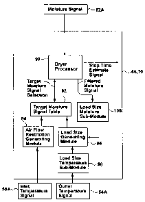
The CPU 66 and the ROM 70 may be configured as shown in Figure 3
to comprise a dryer processor 90. Processor 90 estimates the stop time and
controls the stopping of the dryer 10 based on a moisture signal 52A received
from the moisture sensor 52. The processor 90 filters the moisture signal and
compares this with a target moisture signal to control the operation of the
dryer 10. There are many common methods and systems for filtering the
moisture signal. For more detailed information on the filtering of this
signal,
reference may be had to published Canadian patent application 2,345,631
which was published on November 2, 2001. In accordance with the present
invention, the processor 90 selects a target moisture signal from a target
moisture signal table 92.
-11-
CA 02505565 2005-04-28
CWC -248
Referring to Figure 4, the target moisture signal table is shown broken
into four quadrants. Each quadrant represents a different target voltage given
by the letters Tl, T2, T3, T4. The target voltage to be utilized by the
processor
90 is dependant upon input parameters received from air flow generating
module 94 and load size generating module 96. The air flow generating
module 94 provides either a first air flow parameter or a second air flow
parameter to the target moisture signal table 92. The load size generating
module 96 provides either a small load parameter or a large load parameter
to the target moisture signal table 92. Accordingly, the quadrants shown in
Figure 4 represent four target voltages. Target voltage T, is associated with
a
small load input parameter and a second air flow parameter being received
respectively from the modules 96 and 94. The target voltage T2 of the target
moisture signal table 92 is chosen when a large load parameter is received
from the module 96 and a second air flow parameter is received from module
94. Target voltage T3 is selected when a small load input parameter is
received from module 96 and a first air flow parameter is received from
module 94. Also, target voltage T4 is utilized by the processor 90 when a
large load input parameter is received from module 96 and a first air flow
input parameter is received from module 94. It should be understood that
while four quadrants are shown, it is envisaged that in an alternative
embodiment the target voltage may comprise a selection associated only with
a first air flow or a second air flow parameter. Alternatively, the target
voltage
moisture signal may be derived from either the receipt of a small load
parameter or a large load parameter.
The air flow generating module 94 is connected to the inlet
temperature sensor 56 and receives an inlet temperature signal 56A. The
inlet temperature signal 56A is the temperature of heated air entering into
the
drum 12.
Referring to Figure 5 there is shown four curves 101, 102, 104, and
106 showing the temperature rise at the inlet to the drum 12 for four
different
air flow conditions as would be sensed from inlet temperature sensor or
thermister 56. It should be understood that the these curves are related to a
-12
CA 02505565 2005-04-28
CWC -248
cap type of air flow restriction utilized when testing the dryer. Other types
of
restrictions, such as, for example, cone type restrictions may be used to
generate similar curves. The curves are thus generated to be representative
of air flow blockage in a dryer exhaust associated with the length of exhaust
venting between the dryer and atmosphere. The size of the restrictions
mentioned hereinafter correspond inversely to a vent length. That is, the
greater the restriction or blockage, the smaller the air flow restriction size
and
the longer the venting. Curve 101 is exemplary of the temperature rise in a
dryer having an air flow restriction of 3.5 inches. Curve 102 is exemplary of
an air flow rise in a dryer having a restriction of 2.65 inches. Curve 104 is
exemplary of a temperature rise in a dryer having an air flow restriction of
1.75 inches. Curve 106 is exemplary of a temperature rise at the inlet of a
dryer drum having an air flow restriction of 1.5 inches. Line 108 represents a
predetermined slope which is discussed in more detail hereinafter. From the
slope of the curves it is seen that about 120 seconds, or 2 minutes, into the
drying cycle is sufficient time to determine the slope of each of the curves,
compare the slope with the predetermined slope value 108 and, from the
comparison, generate an air flow parameter. The initial rate of the
temperature increase is proportional to the air flow rate and air flow
restriction, and therefore to the vent length used in the dryer. The air flow
parameter is also independent of the load type and size. It should be
understood that while the detailed description relates to an air flow
parameter
being generated that relates to a measurement of air flow restriction or
blockage, the air flow parameter may also be obtained by testing the dryer
utilizing a measurement of air flow through the dryer.
Referring to Figure 6 there is shown the steps executed by the air flow
restriction generating module 94 to generate either the second air flow
restriction or the first air flow restriction parameter. At step 110, the
module
94 reads the inlet temperature from the thermistor or temperature sensor 56
and thereby senses the inlet temperature of air entering into the drum 26.
The module 94 then determines a running average of the inlet temperature at
step 112 and stores this value or running average in a circular buffer 114. By
-13-
CA 02505565 2005-04-28
CWC -248
taking a running average of the inlet temperature, which may be an average
of 8 temperature samples, the average compensates for potentially any noise
in the sensed temperature. This averaging may be the average of eight
consecutive samples followed by the average of the next mutually exclusive
eight consecutive samples. Alternatively the average may comprise
averaging eight samples after each eighth sample such that each average is
calculated for each sample and the proceeding 7 samples. It should be
understood that any number of samples other than eight may be chosen for
determining the average so long as the number of samples and the time
delay between samples effectively compensates for noise in the sample set.
At step 116 the module 94 determines the slope from the inlet temperature
average values stored in a circular buffer. The circular buffer in step 114
stores two values and with each new value stored the oldest value is erased
from the buffer. Similarly, the circular buffer 116 also stores the last slope
and the next slope being determined eliminates or erases the previous slope.
In this way the circular buffers 114 and 116 require minimal storage space in
memory. At step 118 module 94 determines if 120 seconds or 2 minutes has
elapsed. If the 2 minutes has elapsed then no more averages and slopes are
determined. For every average that is determined under the two minute
period, this average is sent to a buffer 120 which saves the maximum slope.
That is the slope determined at 116 is compared with the previous slope
saved in this buffer 120. Accordingly during the initial two minute time
period
only the maximum slope value associated with the temperature rise is stored
in buffer 120 by the module 94. In effect, the module 94 has measured a first
slope or maximum slope corresponding to the temperature rise of the inlet
temperature of air entering the drum during a first initial time period of
operation of the dryer. At decision step 122, processor 94 determines if this
maximum or first slope corresponds to a predetermined slope or limit. This
limit is graphically shown in Figure 5 as the straight slope line 108. Line
108
is retrieved from the memory at step 124. If the slope is greater than the
limit,
a second air flow signal or blocked exhaust signal is returned to the target
moisture signal table 92 at step 128. If the maximum slope measured is less
-14-
CA 02505565 2007-05-31
CWC -248
than or equal to the predetermined slope or limit associated with curve 108,
then a first air flow signal associated with a free exhaust is returned at 126
to
the target moisture signal table 92. In the embodiment shown in Figure 5, the
slope of line 108 corresponds to a predetermined limit of an air flow of which
corresponds to an household average of exhaust conditions.
The generation of the load size parameter in the load size generating
module 96 utilizes a load size temperature sub-module 98 and a load size
moisture sub-module 100.
The load size temperature sub-module 98 generates one of the first
small load signal and a first large load signal that is sent to the load size
generating module 96. This first small or large load signal is a temperature
related signal related to the output temperature signal 54A provided by the
outlet thermistor or temperature sensor 54.
Referring to Figure 7 there is shown a set of curves 130, 132, 134,
138, and 140 which show the rise in the outlet temperature from the drum 26
over time. In particular the time range shown is for 300 seconds or 5 minutes.
Curve 130 is exemplary of a load size of about twelve pounds. Curve 132 is
exemplary of a load size of about seven pounds. Curve 134 is exemplary of a
load size of about four pounds. Curve 138 is exemplary of a load size of
about two pounds. Curve 140 is exemplary of a load size of about one
pound. Line 142 represents a predetermined slope value for a load size of
approximately four pounds. The initial rate of temperature increase at the
outlet of the drum 26 is proportional to the load size and the fabric. This
rate
of temperature increase is also independent of the restriction or any other
ambient conditions. The temperature rise is dependent upon the energy
source be it gas or electric.
The load size temperature sub-module 98 executes the steps shown in
Figure 8 to generate a temperature load size signal which could be either a
first small load size signal or a first large load size signal dependent upon
the
slope of the curve of a temperature rise at the outlet of the drum relative to
the predetermined line or slope at 142. At step 144, module 94 senses the
outlet temperature of the air exiting the drum by reading the outlet
-15-
CA 02505565 2007-05-31
CWC -248
temperature from the thermistor 54. At steps 146, 148, 150 and 152 module
94 measures a slope corresponding to the rise of the outlet temperature
during a time interval of five minutes from the start of operation of the
dryer.
The measurement of this slope is determined at 146 by determining the
running average of the outlet temperature over a predetermined number of
successively sampled outlet temperature values. This might be groups of
eight samples of temperatures where an average is determined and then a
mutually exclusive second set of eight samples where another average is
determined. Alternatively the averaging may comprise an average
determined for each successive sample for that sample and the preceding
seven samples. The running average of the outlet temperature is stored in a
circular buffer 148. By looking at running averages of the outlet temperature,
the module 98 compensates for noise in the outlet temperature signal 54A.
By storing the signal in a circular buffer 148, minimal amount of memory is
required as this buffer stores two successive samples. With the generation of
every new sample average, the oldest sample average is erased from the
buffer.
The slope of the temperature rise is determined at step 150 wherein
the average outlet temperature values stored in the circular buffer 148 are
compared to determine the gradient or slope of temperature change. The
slope values are calculated at step 150 and the slope value is sent to the
buffer 154. Once five minutes has elapsed at step 152, no new slope values
are calculated and the slope value saved at buffer 154 will be the maximum
slope value of all the slope values calcuiated at step 150. It should be
understood that the buffer 154 compares each slope value received and only
stores the slope value that has the maximum slope.
The maximum slope at 154 after five minutes has elapsed is then
compared at step 156 with a maximum slope limit that is stored in the
memory at 158. This predetermined slope limit 158 corresponds to the slope
of line 142 shown in Figure 7 and in this embodiment corresponds to a load
size of 4 pounds. It should be understood that the 4 pound load size is a
preferred choice and that other slopes may be chosen corresponding to other
-16-
CA 02505565 2005-04-28
CWC -248
weight values. In the event that the maximum slope stored in buffer 154 is
greater than the predetermined load size limit, then a small load signal is
returned at 160 to the load size generating module 96. In the event that the
maximum slope of the saved slope in buffer 154 is less than or equal to the
predetermined slope stored in memory 158, then a large load return signal is
forwarded from the sub-module 98 to the load size generating module 96.
While the load size signal generated by module 96 may be sufficient to
generate a load size parameter for the target moisture signal table 92, it is
recognized that the temperature increase determined at the outlet is a less
precise measurement than the temperature increase determined at the inlet.
Accordingly, the present invention employs a complimentary indicator for the
load size generating module. This additional or complimentary indicator is
shown as the load size moisture sub-module 100 in Figure 3.
The load size moisture sub-module 100 described in the detailed
description operates in accordance with the flow chart shown in Figure 9
which to the determination of a minimum filtered voltage from the filtered
voltage. It should be understood that the filtered voltage is proportional to
the
resistance of the clothes, and when the filtered voltage is chosen to have a
low value for clothes that are wet and a higher value when clothes are dry, as
in the detailed description, then a minimum filtered voltage is determined. In
embodiments where the filtered voltage is chosen to be high for clothes that
are wet and lower for clothes that are dry, then a maximum filtered voltage is
determined, and the logic set out for Figure 9 and discussed below would be
the inverse. In Figure 9, the load size moisture sub-module 100 is responsive
to the filtered moisture signal at step 170 determined by the dryer processor
90. The load size moisture sub-module 100 generates a second small load
signal or a second large load signal when the minimum filtered voltage is
respectively less than or greater than a filtered voltage limit. The load size
moisture sub-module executes this using the steps shown in Figure 9. In the
event the dryer is operating in the first three hundred seconds or five
minutes,
the load size moisture sub-module 100 does not return a signal to the load
size generating module 96. Once three hundred seconds has elapsed at step
-17-
CA 02505565 2005-04-28
CWC -248
174, the load size moisture sub-module 100 takes the minimum filtered
voltage level determined at step 172 and compares it in step 178 with a
filtered voltage limit from step 176. The filtered voltage limit is stored in
memory. In the event that the minimum filtered voltage is greater than the
filtered voltage limit then a small load signal is generated at step 180 to
the
load size generating module 96. In the event that the minimum filtered
voltage is less than or equal to the filtered voltage limit, then a large load
size
signal is generated at step 182 by the load size moisture sub-module 100 and
sent to the load size generating module 96. The predetermined filtered
voltage limit is chosen to represent a load size of approximately four pounds.
It should also be understood that in an alternative embodiment that a large
load signal may be returned to the load size generating module when the
minimum filtered voltage equals the filtered voltage limit.
The load size generating module 96 then compares the signals
received from the load size temperature sub-module 98 and the load size
mqisture sub-module 100. The load size generating module 96 compares
these two signals and when the signals match i.e. the load size temperature
signal and the load size moisture signal are in agreement, then the load size
generating module outputs to the target moisture signal table a parameter
indicative of the matching large load or small load parameter condition. In
the
event that the load size moisture sub-module 100 generates a load size
signal that is the opposite of the load size temperature signal generated by
the load size temperature sub-module 98, then the load size generating
module 96 determines which one of the load size temperature signal and the
load size moisture signal is furthest from its respective limit and chooses
that
furthest signal as the load size parameter to be sent to the target moisture
signal table 92.
With the air flow restriction generating module 94 and the load size
generating module 96 both inputting back to the target moisture signal table
92 parameter values associated with air flow restriction and load size, the
dryer processor 90 is then able to select the target value for the moisture
-18-
CA 02505565 2005-04-28
CWC -248
signal during the initial stages of start up of the dryer which more
appropriately represents conditions in the dryer.
While Figure 9 relates to a load size determination with respect to a
minimum filtered voltage limit where wetter clothing is chosen to have a lower
voltage, the load size determination could be just as effective using a
maximum filtered voltage limit where wetter clothing is chosen to have a
higher voltage. For a maximum filtered voltage, the MFV of blocks 172 and
178 would represent a Maximum filtered voltage and the operator in
comparison block 178 would be inverted to be a less than operator. To
describe both the maximum and minimum filtered voltage conditions within
the scope of the present invention, the sub-module 100 effectively determines
an extremum filtered voltage and compares this extrememum filtered voltage
with a filtered voltage limit. As a result of this comparison an additional
small
or large load parameter or signal is generated.
It should be understood that the present invention does not utilize
precise air flow restriction values or the load size values for the dryer but
instead provides parameters that are indicative of two potential air flow
restriction states or two potentiai load size states. The use of the two
states
for each parameter conserves on the amount of memory required by
controller 58. It should be understood that in an alternative embodiment,
where more memory is available, then more than one predetermined limit
could be used. That is the load size generating module and the air flow
restricting module are adapted to each return three parameters respectively
indicative of load size and of air flow restriction, then this results in nine
target
voltages being stored in the target moisture signal table. While more target
moisture signal values are beneficial to the dryer processor 90 estimation of
stop time for the dryer, the present invention using two states generating
four
target moisture values is an improvement over the use of one target moisture
value.
While the invention has been described in terms of various specific
embodiments, those skilled in the art will recognize that the invention can be
-19-
CA 02505565 2005-04-28
CWC -248
practiced with modifications within the spirit and scope of the present
invention as disclosed herein.
-20-