Note: Descriptions are shown in the official language in which they were submitted.
CA 02505728 2005-05-10
WO 2004/046006 " 1 " PCT/IT2003/000748
RE1NINDING MACHINE WITH GLUING DEVICE TO GLUE THE FINAL
EDGE OF THE LOG FORMED AND RELATIVE WINDING METHOD
DESCRIPTION
Technical field
The present invention relates to a method for producing logs of web
material, for example rolls of toilet tissue, kitchen towels or the like.
The invention also relates to a rewinding or winding machine for form-
ing logs destined to produce small rolls of wound web material.
The invention relates in particular, although not exclusively, to rewind-
ing machines of the peripheral type, i.e. in which the log is formed in a wind-
ing cradle in contact with moving elements that transmit rotatory movement
to the log through surface contact.
State of the art
Currently, to produce rolls of toilet tissue, rolls of kitchen towels or
similar products a web material is unwound from one or more parent reels of
large diameter, coming directly from the paper mill, and predetermined quan-
tities of web material are rewound on tubular winding cores to obtain logs of
a
length equivalent to the length of the parent reel but with a minor diameter,
equivalent to the diameter of the final product. These logs are subsequently
cut crosswise to their axis to produce logs or small rolls of web material des-
tined to be packaged and distributed. Before cutting the rolls or logs. into
small rolls with minor axial dimensions, the initial free edge of the web mate-
rial must be glued to adhere to the external surface of the log and thereby al-
low subsequent handling, without the risk of accidentally unwinding. the web
material.
The rewinding machines currently used wind the rolls or logs, which
are then conveyed to a gluing unit that glues the final free edge of the web
material. For this purpose, the individual logs are partially unwound and posi-
tioned to apply the glue to the unwound free edge or to a portion of the cylin-
drical surface of the log that is subsequently covered with the final free
edge
of the material by rewinding it.
Examples of gluing units to seal the final edge of a web material form-
ing a log are described in US-A-5242525, EP-A-0481929, US-A-3393105,
US-A-3553055, EP-A-0699168.
CA 02505728 2005-05-10
WO 2004/046006 - 2 - PCT/IT2003/000748
To produce logs of web material rewinding machines of the peripheral
type are preferably used, in which the log being formed is made to rotate
through contact with a plurality of motor-driven winding rollers, a. plurality
of
belts or with combined systems of belts and rollers. Examples of rewinding
machines of this type are described in WO-A-9421545, US-A-4487377, GB-
B-2150536 and others.
With these traditional machines at least a rewindirig machine and a
gluing unit'are required to obtain the. completed and glued log, ready to be
subsequently cut into small rolls. US-A-4487377 describes a method that
makes the use of a gluing unit downstream of the rewinding machine unnec-
essary. In this method, the web material is cut upon termination of winding a
log and the final edge of the web material of the completed log is glued after
cutting by transferring to it a glue previously distributed in annular bands
on
the tubular winding core fed into the winding area. The glue applied to the tu-
bular core also serves to start winding the new log.
This system makes it possible to eliminate the gluing unit, although it
requires a particular configuration of the rewinding machine, with a cutting
blade disposed so as to cooperate cyclically with the winding roller. With a
layout of this type it is not possible to attain the performances currently re-
quired of these machines in terms of production speed and production flexi-
bility. Moreover, the quality of gluing is poor, as the glue is distributed
accord-
ing to arcs of circumference, rather than along a line parallel to the axis of
the
log, which are also spaced at a considerable distance from one another in an
axial direction.
WO-A-9732804 describes a rewinding machine with a gluing unit in-
corporated. Nonetheless, owing to its design and to the layout of the gluing
unit, this rewinding machine is only capable of reaching relatively low
winding
speeds. Indeed, gluing takes place by substantially decreasing the feed
speed of the web material during the exchange phase, i.e. when a finished
log is unloaded from the winding area and winding of a new log commences.
WO-0164563 describes a rewinder wherein, upon termination of wind-
ing a log, a first glue is applied to the web material to seal the free edge
of
the formed log. A second glue is applied to the new winding core before it is
fed to the machine. The first glue is applied with a system of nozzles, which
CA 02505728 2005-05-10
WO 2004/046006 - 3 - PCT/IT2003/000748
have some drawbacks, in particular due to the fact that, especially at high
production speeds, they are unable to apply the glue in a precise and definite
way. The glue applied to glue the final edge of each log is not distributed op-
timally, especially when the production speed (that is the feed speed of the
web material) is high. This poses a considerable problem, in particular when
producing rolls of toilet tissue or the like with a small diamefier,
especially for
domestic use where the accuracy of gluing the free edge of the log is essen-
tial.
ObLects and summary of the invention
The object of the present invention is to provide a method and a re-
winding machine for producing logs of wound web material, which make it
possible to accurately glue the final edge of the logs or logs, without
requiring
a gluing unit downstream of the rewinding machine or incorporated in it.
According to a particular aspect a further object of the present inven
tion is to provide a method and a machine that make it possible to attain high
performances in terms of production flexibility.
In substance, according to the invention, a rewinding machine is pro-
vided, preferably although not exclusively of the peripheral type, comprising
in combination: winding elements to wind the web material in logs; means to
sever the web material upon termination of winding each log; at least a first
glue dispenser to apply a first glue to a portion of said web material, in
prox-
imity to a severing line, along which the web material is severed upon termi-
nation of winding a log to form a final free edge and an initial free edge,
said
first glue gluing the final free edge of the log. Characteristically,
according to
the invention the first glue dispenser comprises a mechanical element that
touches the web material upon termination of winding each log, to transfer
said first glue to the web material.
When, according to the preferred embodiment of the invention, the re
winding machine is of the peripheral type, it comprises a winding cradle and
at least a first winding element around which said web material is fed. The
glue dispenser can cooperate with said first winding element, the web mate-
rial passing between the glue dispenser and the winding element.
The use of a mechanical element to apply glue through contact with
the web material, rather than nozzles that spray glue on the web material,
CA 02505728 2005-05-10
WO 2004/046006 - 4 - PCT/IT2003/000748
makes it possible to obtain a product of higher quality, wherein the free edge
of the log is easily detached to allow use of the roll by the user, without
dam-
aging the layers of web material below, with minimum waste of material and
accurate and precise metering of the glue.
The glue to make the final free edge of the log formed adhere can be a
liquid or semi-liquid glue. Nonetheless, it would be possible also .to use a
non-liquid glue, for example in the form of a double-sided adhesive tape. In
this case, the glue dispenser is provided with an element that if necessary
prepares a length or several lengths of adhesive tape and subsequently ap-
plies it or them to the web material. The use of a non-liquid glue has the ad-
vantage of not weakening the web material and thereby does not create a
preferential tear line or area other than the perforation line chosen to sever
the web material. When, on the contrary, the glue is liquid .or semi-liquid,
in
certain cases the glue can be applied subsequent to tearing or severing the
web material, thereby preventing the material from tearing along the line of
application of the glue instead of along the perforation line.
Winding can take place around a tubular core, on which a second glue
can be applied if necessary by means of a second dispenser. The first and
the second glue may be of a different nature, to satisfy the different require-
ments to glue the final free edge of a complete log and to fasten the initial
free edge of a new log to the winding core. However, the invention may also
be implemented on a rewinding machine that produces logs without a central
winding core, such as a rewinding machine of the type described in EP-A-
0580561.
Alternatively, the invention may be incorporated in a rewinding ma-
chine wherein the log is formed around a spindle or tubular winding core that
is subsequently removed from the log, to obtain a finished product without a
central core, as described for example in WO-A-0068129 or in WO-A-
9942393. In this case a glue is not normally applied to the winding core or
spindle but other temporary fastening systems of the initial free edge are
used. Differently, water can be used instead of an actual glue and when it
r
dries or is absorbed by the first turns of the wound material this allows the
winding spindle or core to be subsequently removed with ease from the log
formed.
CA 02505728 2005-05-10
WO 2004/046006 - 5 - PCT/IT2003/000748
According to a particularly advantageous embodiment of the invention,
the first glue dispenser applies said first glue to a portion of the web
material
fed around the first winding element, which functions as a counter-pressure
element.
The mechanical element of the first dispenser may be a rotating ele-
ment, which is operated in synchronism with the exchange cycles, that is with
the phases in which the web material is severed, a finished log is unloaded
and a winding of a new log commences. This allows glue to be applied relia-
bly and accurately, without damaging the web material.
According to an advantageous embodiment of the invention, the me-
chanical element that applies the glue to the web material has a pad suitable
to pick up the glue and to touch the web material, in order to transfer at
(east
part of the glue picked up to it. The glue may be picked up fl-om a tank, from
a dispensing roller or from another suitable element.
When the rewinding machine is designed to perform winding around a
winding core, it typically comprises a feeder to feed the tubular winding
cores
on which the logs are wound to the winding cradle. Winding can commence
by fastening the initial free edge of the new log to the tubular winding core
by
means of a glue. As already mentioned, this glue may be equal to or different
from, as regards chemical and/or physical properties, the glue applied to seal
the final free edge of the previously formed log. However, winding of the ini-
tial free edge of the new log around the winding core may be commenced in
another way, instead of using a glue. For example, the winding core or spin-
dle may have a suction system, as described in WO-A-0068129, or may be
electrostatically charged, or yet again the first turn may be wound around the
winding core with the aid of external air jets, or even a combination of the
aforesaid means.
When the rewinding machine uses a feeder to feed the cores to the
winding area, the mechanical element of the first glue dispenser may be as
sociated with said feeder, for example it may be integral with it. In this
way,
correct synchronism between application of the glue to glue the final free
edge of the completed log and feed of a new core are simple to obtain.
Moreover, a particularly simple rewinding machine with a limited number of
mechanical elements is obtained.
CA 02505728 2005-05-10
WO 2004/046006 ' 6 - PCT/IT2003/000748
For example, the feeder of the cores may have an oscillating or rotat-
ing seat, with which the mechanical element of the glue dispenser is integral.
According to a different embodiment, the means to sever the web ma-
terial upon termination of winding each log comprise a rotating severing ele-
ment, cooperating with the first winding element (typically a winding roller).
In
this case, advantageously, the mechanical element of the first glue dispenser
can be associated with said severing element. For example, the mechanical
element of the glue dispenser may be integral with the severing element. Al-
ternatively, it may be part of the actual severing element. Also in this case
the
structure . of the rewinding machine is considerably simplified and its me-
chanical elements are reduced.
In an embodiment of this type when the severing element is in contact
with the web material it may have a peripheral speed differing from the pe-
ripheral speed of said first winding element. According to the layout of the
machine, this speed may be higher or lower than the speed of the first wind-
ing element. In the first case the web material is severed between the posi-
tion in which the severing element touches the web material and the new
winding core fed to the machine. In the second case severing typically takes
place between the severing element and the log in the completion phase.
According to the solution adopted, the position of the mechanical element
that applies the glue to seal the final free edge of the finished log changes
in
respect of the severing element.
In a per se known way, the rewinding machine can have a rolling sur-
face defining with the first winding element a channel for feeding the winding
cores. The winding cores are fed into said channel and made to roll inside it
before the web material is severed.
To obtain clean gluing of the final free edge of each log, consequently
making the roll easy to open when it is used by the final consumer, the first
glue dispenser applies glue along a longitudinal band, continuous or broken,
on the web material, positioned at a suitable and modifiable distance from the
edge of the material.
The invention also relates to a method to produce logs of wound web
material, comprising the phases of: winding a quantity of web material to form
a first log in a winding area; upon termination of winding said first log,
sever-
CA 02505728 2005-05-10
WO 2004/046006 ~ - 7 - PCT/IT2003/000748
ing the web material to create a final edge of the first log and an initial
edge
to form a second log; applying a first glue to a portion of the web material
destined to remain wound on the first log, in proximity to the final free
edge,
which is glued to the first log unloading said log from the winding area. Char-
s acteristically, according to the invention, the first glue is applied to the
web
material by a mechanical element that comes into contact with said web ma=
terial. Application may take place before or after severing of the web
material.
Further advantageous characteristics and embodiments of the rewind-
ing machine and of the method according to the invention are indicated in the
appended claims.
Brief description of the drawings
The invention shall now be better understood by following the descrip-
Lion and accompanying drawing, which shows a non-limiting .practical exam-
ple of the invention. In the drawing:
Figures 1 to 4 show a first embodiment of the rewinding machine ac-
cording to the invention in four different moments of the winding cycle, in a
schematic side view;
Figures 5 to 7 show a second embodiri~ent of the rewinding machine
according to the invention in three different moments of the winding cycle,
again in a schematic side view;
Figures 8 to 11 show a third embodiment of the rewinding machine
according ~ to the invention in four different moments of the winding cycle,
again in a schematic side view;
Figures 12 to 15 show a fourth embodiment of the rewinding machine
according to the invention in four different moments of the winding cycle,
again in a schematic side view; and
Figures 16 to 20 show a modified embodiment of the invention, in dif-
ferent operating positions of the rewinding machine.
Detailed description of the preferred embodiments of the invention
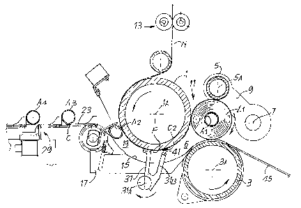
Figures 1 to 4 show, limited to its principal elements, a first embodi-
ment of a rewinding machine according to the invention in four distinct posi-
tions during the winding cycle.
The rewinding machine, indicated as a whole with 2, comprises a first
winding roper 1, rotating around an~ axis 1A, a second winding roller 3, rotat-
CA 02505728 2005-05-10
WO 2004/046006 - $ - PCT/IT2003/000748
ing around a second axis 3A parallel to the axis 1A, and a third winding
roller
5, rotating around an axis 5A parallel to the axes 1A and 3A: The winding
roller 5 is supported by oscillating arms 9 hinged around an oscillation axis
7.
The three winding rollers 1, 3 and 5 define a winding cradle 11 inside
which, in the position shown in Figure 1, a first log L1 of web material is
found in the final winding phase.
A nip 6 is defined between the winding rollers 1 and 3 through which
the web material N passes, which is wound around a tubular core A1 to form
the log L1. The web material N is fed around the first winding roller 1 and,
be-
fore reaching it, through a perforator unit 13 that perforates the web
material
N along the perforation lines equidistant and substantially orthogonal to the
direction of feed of the web material. In this way the web material N wound
on the log L1 is divided into sheets that can be separated individually by be-
ing torn by the final user.
A rolling surface ,15, essentially concave cylindrical and substantially
coaxial to the winding roller 1, extends around a portion of said winding
roller
1. The rolling surface,15 is formed by a series of strips parallel to and
spaced
apart from one another, one of which 'is shown in the drawing and indicated
with 17, the others being superimposed on it. The strips 17 terminate with a
narrow portion that extends into annular channels 3B of the second winding
roller 3. The layout is analogous to the one described in WO-A-9421545, the
content of which may be referred to for greater details concerning the con-
struction of this rolling surfaces.
The rolling surface 15 forms, with the~external cylindrical surface of the
winding roller 1, a channel 19 to feed the tubular winding cores. The channel
19 extends from an inlet area 21 to the nip 6 between the winding rollers 1
and 3. It has a height, in a radial direction, equal to or slightly less than
the
diameter of the tubular winding cores, which must be sequentially fed into the
winding area in the manner described below.
In practice, the channel may increase gradually in height from the inlet
to the outlet, to facilitate the increase in the diameter of the log in the
first
winding phase, when the first turns of web material are wound around the tu-
bular core that rolls in the channel. For example, the. height of the channel
may be slightly less than the diameter of the winding core at the inlet of the
CA 02505728 2005-05-10 -
WO 2004/046006 - 9 - PCT/IT2003/000748
channel and slightly more than it at the level of the outlet.
The tubular winding cores are carried to the inlet 21 of the channel 19
by a conveyor 23 comprising two or more flexible elements parallel with one
another and equipped with pushers 25 that pick up each single tubular wind-
ing core A (A1, A2, A3, A4) from a hopper or other container, not shown.
Along the path of the cores A1-A4 carried by the conveyor 23 is a glue dis-
penser, indicated as a whole with 29, of a per se known type, which applies a
longitudinal band of glue, continuous or broken, to each of the tubular cores
traveling over it. It must be understood that other conveying and gluing sys-
tams may be used to convey the tubular winding cores and to apply glue to
them, preferably along longitudinal lines, that is parallel to the axis of
said
cores.
In the layout in Figure 1 the tubular winding cores A2 and A3 have al-
ready been equipped with a longitudinal band of glue, indicated with C. This
band may be broken in positions corresponding to the positions in which the
strips 17 and the pushers 25, with the respective chains carrying them, are
disposed.
The tubular winding core A2 is in proximity to the inlet 21 of the chan-
nel 19 and was fed by an auxiliary feeder 30 of a per se known type (see for
example WO-A-9421545) or in any other suitable way, for example by a sud-
den movement of the conveyor 23 and through the effect of the thrust of the
pusher 25. The auxiliary feeder 30 may be constituted with a comb structure
to penetrate between the strips 17. The longitudinal band of glue C may be
broken even at the level of the teeth forming the structure of the auxiliary
feeder 30.
The log L1 formed around the tubular core A1 is in the completion
phase. In an intermediate position, along the extension of the channel 19 is a
severing element 31 that rotates around an axis of rotation 31A parallel to
the
axis of the winding rollers 1, 3, 5. In the position of Figure 1 the end of
the
severing element 31 is in contact with the web material N in an intermediate
position along the arc of contact of the material with the winding roller 1.
In
the contact point with the severing element 31 the web material N is pinched
between this element and the winding roller 1.
The peripheral speed of the severing element 31 is greater than the
CA 02505728 2005-05-10
WO 2004/046006 - ~ ~ ' PCT/IT2003/000748
peripheral speed of the winding roller 1 and therefore than the feed speed of
the web material N. The latter is thereby drawn and tensioned in the portion
between the point pinched by the severing element 31 and the point pinched
by the tubular core A2. Tensioning causes the_web material N to slide on the
external surface of the winding roller 1 and finally tearing of the web
material
N along a perforation line produced by the perforator 13 and disposed be-
tween the new core A2 and the contact point with the severing element 31.
Sliding of the material can be facilitated by the presence of annular bands
with a low coefficient of friction on the cylindrical surface of the winding
roller
1.
In practice, the severing element 31 is constituted by a series of teeth
or slats parallel with one another and integral with a center body rotating
around. the axis 31A. Each of said teeth or slats passes between adjacent
strips 15 in order to pass through the channel 19.
Each of the teeth or slats forming the severing element 31 is equipped
at its end with a pad 41 impregnated with glue. When the .pad 41 is pressed
against the web material N it applies to it part of the glue with which it is
im-
pregnated. Consequently, a broken longitudinal band C2 of glue is applied
along the crosswise extension of the web material N.
Figure 2 shows a successive phase of the operating cycle of the re-
winding machine. In this phase the web material N has been torn between
the contact point with the severing element 31 and the new winding core A2
fed into the channel 19. The core A2 is rolling along the channel 19, in con-
tact with the fixed rolling surface 15 and the rotating surface of the winding
roller 1. The free edge Li that was formed following severing adheres to the
tubular core A2 thanks to the band of glue C, while the free edge Lf, which
constitutes the final edge of the log L1, will be glued to the log L1, by the
band of glue C2 applied by the pads 41 in the manner described hereunder.
Figure 3 shows a subsequent phase wherein the severing element 31,
continuing its rotatory movement around the axis 31A, has left the channel
19, while the core A2, on which the first turn of web material is being wound,
.
moves towards the nip 6 between the winding rollers 1 and 3. The finished
log L1 starts to move away from the winding cradle by means of a variation in
the peripheral speed between the rollers 3 and 5, for example by acceleration
CA 02505728 2005-05-10
WO 2004/046006 - 11 - PCT/IT2003/000748
ofi the roller 5 and/or deceleration of the roller 3.
To make the final free edge Lf adhere to the periphery of the finished
log, this is made to rotate between the two rollers 3 and~5, through appropri-
ate control of their peripheral speeds. By making the log L1 make at least
one complete turn in this position the final free edge Lf is pressed against
the
log and glued to it.
After the web material has been severed and before the final free edge
adheres completely to the finished log, the tail portion of the web material
adheres lightly to the winding roller 1 through the aerodynamic effect and
also due to the presence of annular areas of material with a high coefficient
of friction that in a per se known way are provided on the cylindrical surFace
of the roller 1 and tend to hold the web material N.
The difference in peripheral speed between the rollers 3 and 5, after
adhesion of the final free edge Lf to the finished log L12, will unload the
log to
an unloading surface 45. To allow ejection of the log the upper winding roller
5 is raised and subsequently lowered to come into contact with the new log
L2 to be formed in the subsequent cycle.
Figure 4 shows a moment during winding of the new log L2 of web
material around the tubular core A2 that has reached the winding cradle be
tween the rollers 1, 3 and 5. The roller 5 has been lowered and is in contact
with the log L2 being formed. It will oscillate gradually upwards to allow in-
crease in the diameter of the log. The log L1 has been completely unloaded,
while the new core A3 has reached a stand-by position to be fed at a subse-
quent moment (when the log L2 has been completed) into the channel 19 by
the pusher 30.
Figure 4 also shows how the pads 41 carried at the ends of the teeth
or slats forming the severing element 31 are soaked with glue. For this pur-
pose they are brought into contact with a glue applicator, indicated as a
whole with 47. In the example shown this applicator has a glue tank inside
which a pick-up roller rotates, partially immersed in the glue contained in
the
tank. Other solutions are naturally possible, such as a system of nozzles, a
slit to deliver glue by overflow or the like. The severing element may remain
in this angular position during winding of the log L2 and only recommence its
rotatory .movement just before the log L2 is completed.
CA 02505728 2005-05-10
WO 2004/046006 - 12 - PCT/IT2003/000748
In this embodiment glue is applied by the severing element 31 that
severs, i.e. tears the web material. This on the one hand simplifies the struc-
ture of the machine, as gluing takes place without providing an additional
mechanical element, but using for this purpose (with appropriate modifica-
tions) an element already present for other operations. On the other hand this
solution makes it possible to maintain, during the exchange phase, that is the
phase to sever the web material, unload the log and commence a new wind-
ing cycle, an essentially continuous feed speed of the web material.
Figures 5, 6 and 7 show - in different operating positions - an em-
bodiment modified in respect of the one shown in Figures 1-4. Equal num-
bers indicate parts equal or corresponding to those in the previous embodi-
ment. In this case the severing element, once more marked with 31, does not
operate directly as a glue applicator, but has an assembly of rods 31 B inte-
gral with it, at the ends of which pads 41, destined to be soaked with glue,
are integral. When the severing element is in the operating position, as
shown in Figure 5, the pads 41 are in a position further forward in respect of
the severing element 31, that is downstream of it in respect of direction of
feed of the web material N, and no longer in contact with said web material.
With this layout severing of the web material N can be obtained in a point be-
tween the finished log L1 and the point in which the web material N is
pinched between the severing element 31 and the winding roller 1. This is
obtained by operating the severing element 31 at a lower peripheral speed
than the peripheral speed of the winding roller 1. By suitably phasing move-
ment of the severing element 31, and thereby of the glue dispenser 31 B, 41,
with the position of the perforation lines produced on the web material by the
perforator unit 13 it is possible to make the web material tear along a
perfora-
tion line that is positioned between the point in which it was touched by the
pads 41 and the point in which it is pinched by the severing element 31. This
solution is particularly advantageous due to the reduced rotation speed of the
severing dement 31 and of the glue dispenser 31 B integral with it. The lower
rotation speed reduces the centrifugal effect on the glue with which the pads
carried by the dispenser 31 B are soaked and this makes it possible to in-
crease the feed speed of the web material N without the risk of the glue, ow-
ing to the centrifugal force, being sprayed from the dispenser 31B.
CA 02505728 2005-05-10
WO 2004/046006 - 13 - PCT/IT2003/000748
~n the contrary, relinquishing this advantage, also in this embodiment
the severing element 31, and therefore the glue dispenser 31, can be made
to move at a higher peripheral speed than the. peripheral speed of the wind-
ing roller 1, causing the web material N to tear or be severed upstream of the
point in which it is pinched, as described with reference to the previous em-
bodiment.
The glue is applied to pads 41 with a roller applicator, indicated as a
whole with 47. DifFerently to the description in the previous example, in this
case the glue applicator roller is provided with a movement to move if to-
wards and away from the axis of rotation 31A of the unit formed by the sever-
ing element 31 and the dispenser element 31 B, 41. In this way glue is not
applied to the severing element 31. The alternate movement of the glue ap-
plicator. roller may be relatively slow, as it must only act once for each
turn of
the unit 31, 31B around the axis 31A, which takes place once during each
winding cycle, i.e. for each log produced.
According to an alternative embodiment, not shown, the position of the
elements 31 and 31 B can be inverted, in which case the web material N will
be severed necessarily upstream of the point in which it is pinched by the
severing element 31, moving this at a higher peripheral speed to the periph-
eral speed of the winding roller 1 in the severing phase. In this case tearing
or severing of the web material will preferably take place after having
applied
the glue C2 to it to seal ttie final free edge Lf of the log. This is due to
the fact
that the point in which glue is applied is weakened by the liquid content of
the
glue, which, (in the case of paper web material) reduces the mechanical re-
sistance to traction. This could cause the web material to tear at the level
of
the line of glue C2 instead of at the level of the perForation line along
which
tearing has been programmed.
Figures 8 to 11 show, in difFerent operating positions, a further em-
bodiment of the machine according to the invention. Equal numbers indicate
equal or corresponding parts to those in the previous embodiments. Extend-
ing upstream of the nip 6 between the winding rollers 1 and 3 is a rolling sur-
face, indicated once more with 15, which may be constituted by a series of
strips or by a continuous section bar and which extends to a lesser extent
than the rolling surface 15 of the previous embodiments.
CA 02505728 2005-05-10
WO 2004/046006 - 14 - PCT/IT2003/000748
Disposed underneath the inlet of the channel 19 formed between the
surface of the winding roller 1 and the rolling surface 15 is a hopper 81
inside
which the winding cores A1-A4 are fed in sequence, already provided with a
longitudinal band (continuous or broken) of glue C. The cores may be intro-
duced, for example, with a longitudinal movement. A pusher 83, oscillating
around an axis 83A parallel to the axes 1A, 3A, 5A of the winding rollers 1,
3,
5 picks up the core that is positioned time by time in the hopper 81 and
,feeds
it into the channel 19 between the rolling surface 15 and the cylindrical sur-
face of the winding roller 1. The dimension of the channel is equal to or
slightly Less than the external diameter of the tubular core, which is thereby
forced into the channel 19 and made to roll on the fixed surface 15 through
the effect of the rotatory movement of the winding roller around which the
web material N is fed, which is pinched between the core and the roller 1.
Alternative solutions to feed the winding cores into the channel 19 are
naturally possible. For example the cores may be fed by means of a feeder
equipped "with a hypocycloid movement or with any other known system.
Preferably, they will in any case be equipped with a longitudinal band of glue
C, although the use of annular bands of glue is not excluded a priori, which
may also be adopted in the other embodiments described. In this second
case the rolling surface 15, as in the previous examples, will preferably not
be continuous, to prevent part of the glue from remaining attached and ac-
cumulating on it.
Upstream of the inlet to the channel 19, along the feed path of the web
material N, is a glue dispenser indicated as a whole with 85. It comprises one
or more slats 87 rotating around an axis 89, parallel to the axis of rotation
of
the winding roller 1, 3, 5. At the end of the rod or of each rod 87 is an
absor-
bent pad 88, which is soaked with glue, picked up from a glue applicator 91
analogous to the applicator 47. The dispenser 85 makes one turn for each
winding cycle, that is for-each log L produced by the machine. It is disposed
so that the pads 88 touch the web material N fed around the winding roller 1
to leave on it a quantity of glue sufficient to make the free edge of the web
material adhere to the completed log. In the moment of reciprocal contact,
the web material N and the pads 88 have the same speed, so as to avoid any
damage to the web material N.
CA 02505728 2005-05-10
WO 2004/046006 - 15 - PCT/IT2003/000748
In this embodiment the glue dispenser 85 'is in an area with ample
space available and not provided with a rolling surface for the core. It is
therefore possible to design the glue dispenser in other ways to allow the use
of a non-liquid glue. For example, the glue may be composed of a double-
s sided adhesive strip, and the glue dispenser may have a system for unwind-
ing lengths of double-sided adhesive tape and applying them to the web ma-
terial.
Operation of the machine in this embodiment is clearly shown in the
sequence in Figures 8 to 11. In Figure 8 the log L1 has been pi-acti.cally com-
pleted and the subsequent winding core A2 destined to form the subsequent
log, equipped with glue C; has been partially raised from the hopper 81 by
the pusher 83. It is, positioned in front of the inlet of the channel 19 but
has
not yet been brought into contact with the web material N and with the sur-
face 15.
The dispenser 85 is rotating clockwise according to the arrow f85, so
that the pads 88 come into contact with the web material N, moving at the
same speed as it, to deposit a band of glue on it. This is applied downstream
of a perforation line, produced by the perforator 13 and indicated with P,
along which the web material will be torn.
The roller 5 is temporarily accelerated so as to tension the web mate-
rial N. This acceleration commences at a suitable moment, if necessary be-
fore the new core A2 is fed to facilitate tearing of the web material, which
takes place as described hereunder.
In Figure 9 the glue dispenser 85 is no longer in contact with the web
material N while the winding core A2 has been fed into the channel between
the rolling surface 15 and the winding roller 1, so that the web material N is
pinched between the core A2 and the roller 1. The core AZ starts to roil along
the surface 15, while acceleration of the winding roller 5 increases the ten
sion of the web material between the contact point of the roller with the log
formed L1 and the point in which the web material is pinched by the new tu-
bular winding core A2. Acceleration of the roller 5 is controlled so that it
causes the web material to tear along the perforation P when this is between
the core A2 and the log L1, as shown in the position in Figure 10. The final
free edge Lf that is produced is provided with the band of glue C2 applied by
CA 02505728 2005-05-10
WO 2004/046006 - 16 - PCT/IT2003/000748
the dispenser 85. It continues to wind around the finished log L1, which is
moved away by rolling on the surface 45, ,causing adhesion of the free edge
Lf and consequently sealing the log L1. The initial free edge Li remains fas-
tened to the new winding core A2 due to the glue C applied to it. The core A2
continues to roll on the surface 15 until it reaches the nip 6 and
subsequently
the winding cradle defined by the rollers 1, 3 and 5 where formation of a new
log L2 is completed, as shown in Figure 11. This figure also shows a subse-
quent winding core A3 positioned in the hopper 81, to be fed to the machine
by the feeder 83 during the subsequent exchange cycle.
The embodiment in Figures 8 to 11 makes it possible to apply a con-
tinuous line of glue both to the cores and to the web material.
Figures 12 to 15 show yet another embodiment of the invention. Equal
numbers indicate equal or corresponding parts to those in the embodiment in
Figures 1 to 4.
Also in this case the rewinding machine, indicated once again as a
whole with 2, comprises a first winding roller 1, rotating around an axis 1A,
a
second winding roller 3~ rotating around a second axis 3A parallel to the axis
1A, and a third winding roller 5, rotating around an axis 5A parallel to the
axes 1A and 3A and moving around an axis 7 of oscillation, around which
oscillating arms 9 to support the winding roller 5 are supported. The three
winding rollers 1,-3 and 5 define a winding cradle 11 inside which, in the
posi-
tion shown in Figure 12, a first log L1 of web material is found in the final
phase of viiinding.
A nip 6 is defined between the winding rollers 1 and 3 through which
the web material N passes and is wound around to form the log L1. The web
material N is fed around the first winding roller 1 and, before reaching it,
through a perforator unit 13 that perforates the web material N along the per-
foration lines equidistant and substantially orthogonal to the direction of
feed
of the web material. In this way the web material N wound on the log L1 is di-
vided into sheets that can be separated individually by being torn by the
final
user.
A rolling surface 15, essentially concave cylindrical and coaxial to the
winding roller 1, extends around a portion of said winding roller 1. The
rolling
surface 15 is formed by a series of parallel strips 17, which terminate with a
CA 02505728 2005-05-10
WO 2004/046006 - ~ 7 - PCT/IT2003/000748
narrow portion that extends into annular channels 3B of the second winding
roller 3.
The rolling surface 15 forms, with the external cylindrical surface of the
winding roller 1, a channel 19 to feed the tubular winding cores. The channel
19 extends from an inlet area 21 to the nip 6 between the winding rollers 1
and 3. It has a height, in a radial direction, equal to or slightly smaller
than
the diameter of the tubular winding cores. in practice, as specified with
refer-
ence to the first embodiment, the height of the channel may be variable and
increasing from the inlet towards the outlet. In practice, however, the length
of the rolling surface 15 and thereby of the channel formed by it with the
winding roller 1 may be smaller than shown in the appended figures, as this
embodiment does not include a severing element for the web material that
must operate along the extension of the channel.
The tubular winding cores are brought in proximity to the inlet 21 of the
channel 19 by a conveyor 23 comprising two or more flexible elements paral-
lel with each other and provided with pushers 25. Disposed along the path of
the cores A1-A4 conveyed by the conveyor 23 is a glue dispenser, indicated
as a whole with 29, of a per se known type, which applies a longitudinal band
of glue, continuous or broken, indicated with C, to each of the tubular cores
passing over it. This band may be broken in positions corresponding to the
positions in which the strips 77, forming the rolling surface 15, are
disposed.
In the position in Figure 12, the log L1 formed around the tubular core
A1 is in the completion phase in the winding cradle 11. A new winding core
A2 is ready to be fed into the channel 19, in front of the inlet 21. The core
A2
is contained in a feeder 101 equipped with a seat 101A to hold the winding
cores and rotating around an axis 103 parallel to the axis 1A of the winding
roller 1. The feeder 101 has a comb structure so as to penetrate, in its rota-
tory movement around the axis 103, between the strips 17 forming the rolling
surface 15, for the purposes explained hereunder. The individual winding
cores are unloaded in the seat 101A of the feeder by the conveyor 23.
In front of the seat 101A the feeder is provided with a series of pads
105 soaked in glue, which in :the rotatory movement of the feeder 101 come
to touch the web material N fed around the winding roller 1 to apply the glue
destined to seal the final free edge of the completed log to it. The glue is
ap-
CA 02505728 2005-05-10
WO 2004/046006 - 1$ - PCT/IT2003/000748
plied to the pads 105 by a glue applicator 107 analogous to the one de-
scribed with reference to Figures 5 to 7. The contact pressure of the pads
105 on the web material is minimum and their relative speed in respect of the
web material is null, as it is not the duty of these pads to break or sever
the
web material N.
Operation of the machine is clearly shown in the sequence in Figures
12-to 15. In Figure 12 the feeder 101 is rotating around the axis 103 at a pe-
ripheral speed that makes the pads 105 move at the same speed as the web
m~aterial~ N and therefore at the same peripheral speed as the winding roller.
The winding roller 5 may already be accelerating or may be accelerated at a
slightly later moment, to start the operation to unload the log L1 and to ten-
sion the web material N prior to severing. In the example shown, acceleration
of the roller 5 has already commenced, and the log L1 has already been
moved slightly away from the surface of the winding roller 1, with which it
was
in contact in the previous winding phase. Detachment of the log L1 from the
roller 1 may also take place through the effect of deceleration of the lower
roller 3, or through the combined effect of acceleration of the roller 5 and
de-
celeration of the roller 3.
In Figure 13 the feeder 101 has brought the core A2 inside the chan-
nel 19, in contact between the web material N and the rolling surface 15. The
movement of the feeder 101 is controlled suitably so as not to obstruct the
movement to feed the tubular core, which starts to roll on the surface 15
when it comes into contact with it and with the web material N fed around the
winding roller 1.
The longitudinal band of glue C2 applied by the pads 105 is positioned
on a portion of web material downstream of the contact point with the core
A2. As the pads are discontinuous, the band C2 will be broken along its lon-
gitudinal extension. The web material between the completed log L1 and the
new core A2 is tensioned gradually due to acceleration of the winding roller
5.
The tension produced in the web material N at a certain point causes
the material to tear along a perforation line between the core A2 and the log
L1, producing a final free edge Lf of the log and an initial free edge Li that
will
be glued to the new core A2 by means of the glue C. This condition is shown
CA 02505728 2005-05-10
WO 2004/046006 - 1 g - PCT/IT2003/000748
in Figure 14, wherein the log L1 has moved further from the winding cradle
11 and is about to be unloaded onto the unloading surface 45. The new core
A2 is rolling along the rolling surface 15 and the glue C has come into
contact
with the web material N which adheres to it in proximity to the initial free
edge
Li produced by tearing. The feeder 101 continues to rotate clockwise, to bring
the pads 105 in contact with the gluing roller of the glue applicator 107
below.
The feeder 101 continues to rotate until-it has been brought to the stand-by
position in Figure 15. The time available for this movement is slightly less
than the time required to complete the log, and therefore may be relatively
slow.
Figure 15 shows the machine in a subsequent phase wherein the new
core A2 is in the winding. cradle 11 and the new log L2 has started to form
around it. A subsequent winding core A3 has in the meantime been unloaded
into the seat 101A of the feeder, to be fed to the machine during the next ex-
change cycle, when the log L2 has been completed.
In a different development of the inventive concept, the core is utilized
as a mechanical element to transfer the glue. Figures 16 to 20 show an ex-
ample of this development. In practice, a rewinding machine is provided to
produce logs of wound web material, comprising:
~ winding elements to wind the web material and form said logs;
~ a severing element to sever the web material upon termination of winding
each log, to form a final edge of the finished log and an initial edge of a
subsequent log;
~ a feeder to feed tubular winding cores towards said winding elements;
~ at least a first glue dispenser to apply a first glue to said winding cores,
according to at least a longitudinal band,
~ said feeder and said severing element being arranged and controlled so
that upon termination of winding each log, the web material is severed and
said longitudinal band of glue applied to said core is brought into contact
with said web material after it has been severed, so that at least part of the
glue is transferred to the web material in the vicinity of the final free edge
of the finished log, said first glue gluing the final free edge of the log.
With this rewinding machine it is possible to implement a method to
produce rolls of wound web material, comprising the phases of:
CA 02505728 2005-05-10
WO 2004/046006 - 20 - PCT/IT2003/000748
winding a quantity of web material around a first winding core to form a
first log in a winding area;
upon termination of winding said first log, severing the web material to
produce a final edge of the first log and an initial edge to form a second
log' ,
applying~a first glue to a second winding core, said glue being applied
according to at least a longitudinal band essentially parallel to the axis of
said core;
D after severing of said web material, bringing said longitudinal band of
glue applied to the-second core into contact with said web material;
transferring at least part of the first glue from said core to said web mate-
rial, in proximity or at the level of said final free edge, to close the final
free edge of the first log.
Having thus defined the general concepts underlying this layout, a
practical embodiment is described with reference to Figures -16 to 20 and in
particular,with initial reference to Figure 16. The rewinding machine, indi
cated as a whole with 2, comprises a first winding roller 1, rotating around
an
axis 1A, and a second winding roller 3, rotating around a second axis 3A
parallel to the axis 1A. A third winding roller 5, rotating around an axis 5A
parallel to the axes 1A and 3A is also provided. The third winding.roller 5 is
supported by oscillating arms 9.
The three winding rollers 1, 3 and 5 form a winding cradle. A nip 6 is
defined between the rollers 1 and 3, fed through which is the web material N
to be wound, which is fed around the winding roller 1. In the condition in Fig-
ure 16, a first log L1 of web material is found in the winding cradle 1, 3, 5
in
the windirig phase, and the three winding rollers rotate substantially at the
same peripheral speed, equivalent to the feed speed of the web material N.
The log L1 is being wound around a first winding core A1.
Upstream of the winding roller 1 the web material passes through a
perforator, not shown, which forms crosswise perforation lines along the ma
terial N.
A rolling surface 15, substantially concave cylindrical and essentially
' coaxial to the winding roller 1, extends around said winding roller 1. It is
formed by a series of strips 17 parallel to and spaced apart from one another,
CA 02505728 2005-05-10
WO 2004/046006 - 21 - PCT/IT2003/000748
one of which is shown in the figure and the others are parallel to it. The
strips
17 terminate with a narrow portion that extends into annular channels 3B of
the second winding roller 3. The layout is analogous to the one described in
WO-A-9421545, the content of which may be referred to for greater details
concerning the construction of this rolling surfaces.
The rolling surface 15 forms, with the external cylindrical surface of the
winding roller 1, a channel 19 to feed the tubular winding cores. The channel
19 extends from an inlet area 21 to the nip 6 between the winding rollers 1
and 3. It has a height, in a radial direction, equal to or slightly less than
the
diameter of the tubular winding cores, which must be sequentially fed into the
winding area in the manner described below. In practice, the channel may in-
crease gradually iw height from the inlet to the outlet, to facilitate the
increase
in the diameter of the log in the first winding phase, when the first turns of
web material are wound around the tubular core that rolls in the channel. For
example, the height of the channel may be slightly below the diameter of the
winding core at the inlet of the channel and slightly above it at the level of
the
outlet.
The tubular winding cores are carried to the inlet 21 of the channel 19
by a conveyor 23 comprising two or more flexible elements parallel with one
another and equipped with pushers 25 that pick up each single tubular wind-
ing core A (A1, A2, A3, A4) from a hopper or other container 26. Disposed
along the path of the cores A1-A4 carried by the conveyor 23 is a glue dis-
penser, indicated as a whole with 29, of a per se known type, which applies a
longitudinal band of glue, continuous or broken, to each of the tubular cores
traveling over it, that is parallel to the axis of said cores. It must be
under-
stood that other conveying and gluing systems may be used to convey the
tubular winding cores and to apply glue to them, preferably along longitudinal
lines, that is parallel to the axis of said cores. In the example shown, the
glue
dispenser.includes a tank 28 inside which the glue C is contained and inside
which a moving element 34A is immerged. In the example shown the ele-
ment 34A is provided with an alternate movement of immersion as it is con-
nected to an oscillating arm 32A. Other systems may also be used to transfer
glue from the tank to the core that is positioned over the tank each time. In
general, the dispenser is in any case suitable to apply a longitudinal band of
CA 02505728 2005-05-10
WO 2004/046006 - 22 - PCT/IT2003/000748
glue. Figure 16 also shows with a dashed line a second glue dispensing ele-
ment, specular to the first, capable of applying a second band of glue to the
core for the purposes described below. The two longitudinal bands of glue
may also be applied by two separate dispensers that use different glues, also
in view of the different technical properties the glue must have, one being
destined to close the final free edge of~the logs formed and the other to make
the initial free edge of the web material adhere to the new core.
Disposed along the path of the conveyor 23 is a system that causes
the glued cores to rotate around their axis by a determined angle. In the ex-
ample schematically illustrated this is a belt 36 provided with a movement
according to the arrow in the figure. This allows the glued cores to arrive at
the inlet 21 of the channel 19 with the band or bands of glue in the desired
position.
In the layout in Figure 16 the tubular winding cores A2 and A3 have ai-
ready been equipped with a longitudinal band of glue, indicated with C. This
band may be broken in positions corresponding to the positions in which the
strips 17 and the pushers 25, with the respective chains carrying them, are
disposed.
The tubular winding core A2 is in proximity to the inlet 21 of the chan-
nel, into which it is subsequently fed by an auxiliary feeder 30 of a per se
known type (see for example WO-A-9421545) or in any other suitable way,
for example by a sudden movement of the conveyor 23 and through the ef-
fect of the thrust of the pusher 25. The auxiliary feeder 30 may be
constituted
with a comb structure to penetrate between the strips 17. The longitudinal
band of glue C may also be broken at the level of the teeth forming the struc-
ture of the auxiliary feeder 30.
Disposed upstream of the inlet 21 of the channel 19 is a severing ele-
ment for the web material N, generically indicated with 101. It includes a se-
ries of pads 103 carried by an element rotating around an axis 105 by means
of an actuator 107, for example an electric motor controlled electronically so
that the speed and/or position of the pads 103 may be controlled accurately
as a function of the position and/or speed of the remaining elements of the
machine.
In the position in Figure 16 the element 101 is in the operating condi-
CA 02505728 2005-05-10
WO 2004/046006 ~ - 23 - PCT/IT2003/000748
tion, that is in the position in which tearing or severing of the web material
starts or has started. Tearing or severing is obtained thanks to the
difference
in peripheral speed of the pads 103 in respect of the first winding roller 1
and
in respect of the web material N fed around it. Normally, in this phase the
pads 103 rotate at a speed slightly below the peripheral speed of the roller 1
and therefore below the normal feed speed of the web material N. This
causes tensioning and tearing of the material N along the perforation line lo-
cated immediately downstream of the area in which the web material N is
pinched by the pads 103 against the winding roller 1. Figure 16 already
shows severing of the web material, with consequent forming of a final or tail
edge Lf of the material, destined to be wound around the log L1 in the com-
pletibn phase in the winding cradle, and an initial or leading edge Li
destined
to adhere to the new core A2 that will be fed into the channel 19.
In this case, feed of the core A2 is delayed in respect of tearing the
web material, as can be seen from the sequence in the subsequent Figures
17 to 20. It must, however, be pointed out that the moment in time in which
the core is fed may differ. What is relevant is that core insertion and the an-
gular position of the core are timed so that the glue is applied to a portion
of.
the web material downstream of the final free edge of the completed log. (n
practice, the core A2 is fed into the inlet 21 of the channel 19 and therefore
in
contact.with the web material N fed around the roller 1 after tearing or sever-
ing of the web material has already taken place. Figure 17 shows the mo-
ment in which the core comes into contact with the web material N. As it is
forced into the channel 19, it starts to roll on the surface 15 of the channel
19
" and moves forward along said channel, undergoing angular acceleration.
In practice, the core may also be fed into the inlet 21 a,nd therefore be
brought into contact with the web material N before the moment in which the
web material is torn or severed. However, contact between the longitudinal
band of glue C and the web material N takes place after tearing of the web
material and forming of the edges Li and Lf.
The angular position of the core A2 is regulated so that it preferably
comes into contact with the web material N and therefore starts to accelerate
angularly rolling on the surface 15 before the band of glue C comes into con-
tact with the web material. This allows contact between the web material N
CA 02505728 2005-05-10
WO 2004/ 046006 - 24 - PCT/IT2003/000748
and the glue C at a moment in which there is practically no difference in
speed between these two elements, thereby guaranteeing optimal transfer of
glue. In fact, at least part of the glue C is in this phase transferred from
the
core A2 to the web material N in proximity or adjacent to the final free edge
Lf. This quantity of glue guarantees subsequent closing by gluing the final
free edge on the finished log L1.
In Figure 18 the core A2 has already traveled part of its path along the
channel 19. In respect of the position in the previous Figure 17, it is turned
through more or less 360°, so that the band of glue C is back in the
original
position of Figure 17 and, the moment subsequent to this, said band of glue
comes into contact with the initial free edge Li of the web material. This
guar-
antees adhesion of said edge tb the new core and allows winding of the sub-
sequent ,log L2 to commence. Figures 19 and 20 show the moments subse-
quent to transfer of the core AZ to the winding cradle and forming of the log
L2. In the meantime the previously formed log L1 has been unloaded from
the winding cradle in a per se known way.
To guarantee control of the leading and tail edges Li and Lf of the web
materials which is severed upstream of the area of contact with the new core
A2, this embodiment provides a holding system on the surface of the winding
roller 1 which maintains control of the edges Li and Lf from the area in which
they are produced through the effect of the severing element 101 to the area
of contact with the core. In this example, the edges Lf and Li are held pneu-
matically. The winding roller 1 is equipped with a cylindrical sleeve at least
partly perforated. A fixed suction chamber 111 is provided inside the roller
1,
extending for an arc of more or less 180° from an area upstream of the
point
in which the web material N is pinched by the element 101 to an intermediate
area along the channel 19. This guarantees hold, by suction through the
holes in the cylindrical sleeve of the roller 1, of the edges Li and Lf. More-
over, this prevents excessive slackening of the web material upstream of the
element 101 during tearing. Above all, the edge Li is held adhering to the
roller 1 at least until the position in which it is pinched between the core
A2
and the roller 1. The suction chamber 111 terminates its holding effect when
the core.and the initial edge Li have reached the position of Figure 18, so
that
when the holding action on the roller 1 terminates the edge Li can adhere to
CA 02505728 2005-05-10
WO 2004/046006 - 25 - PCT/IT2003/000748
the core A2. In this figure, C2 indicates a band of glue transferred from the
core A2 to the final edge Lf of the completed log L1.
In practice, adhesion of the web material N tb the core may also take
place in a position spaced from the final edge of the initial free edge Li, as
in
any case this area remains wound inside the log to be formed subsequently.
Instead, timing of the various elements of the machine must preferably allow
the glue to close the log, applied to the final edge Lf to be as close as
possi-
ble to the end of the final edge Lf, as this remains exposed on the outside of
the log. The most advantageous condition is for the band of glue transferred
from the core A to the web material N to be around 1 cm from the tearing
edged that is from the perforation line along which the web material is torn.
This guarantees optimal closing and at the same time leaves a free edge for
the final user to grip the web material and open the roll. Correct angular
posi-
tioning of the core during feed into the channel 19 guarantees these optimal
operating conditions.
It is understood that the drawing merely shows an example provided
purely as a practical embodiment of the invention, which may vary in shapes
and arrangements without however departing from the scope of the concept
on which the invention is based. Any reference numbers in the appended
claims are provided to facilitate reading of the claims with refererice to the
description and the drawing, and do not limit the scope of protection repre-
sented by the claims.