Note: Descriptions are shown in the official language in which they were submitted.
CA 02505812 2005-04-29
Title
CANTILEVERED SPRING
Scope of the Invention
[0001] This invention relates to a cantilevered spring and, more particularly,
to a fluid
dispenser with a cantilevered spring preferably of plastic.
Background of the Invention
[0002] Various dispensers and other devices are well known with an actuator
which is
movable between a first position and a second position with a spring biasing
the actuator to a
first position and with the actuator being movable to the second position
against the bias of
the spring and then returning under the resiliency of the spring to the second
position.
Typical springs include metal springs which are selected in view of the
inherent resiliency of
the metal and the fact that spring metals are well known to provide for a long
useful life
against failure. Wall mounted soap dispensers for use in washrooms and the
like are known
in which a manually activated presser is movable between an extended position
and a
retracted position to dispense material and a spring is provided to return the
presser to one of
these positions. Most commonly used springs comprise metal helical coil
springs.
[0003] Many dispensers are formed substantially from plastic which is
recyclable.
Insofar as a soap dispenser may be formed substantially from plastic other
than a metal
spring, the metal spring provides the disadvantage of reducing the ease with
which the
dispenser can be recycled as, for example, to be reground and the plastic
reused. The metal
spring needs to be separately removed before any such grinding process.
[0004] Provision of a separate spring, whether or not metal, has a
disadvantage of
requiring a separate part which requires separate manufacture, inventory and
assembly.
Summary of the Invention
[0005] To at least partially overcome these disadvantages of previously known
devices,
the present invention provides a construction for a cantilevered spring and,
more particularly,
1
CA 02505812 2005-04-29
a cantilevered spring construction adapted to be manufactured from plastic
preferably as an
integral part of a dispensing unit.
[0006] An object of the present invention is to provide an improved
construction for an
elongate cantilevered spring.
[0007] Another object is to provide a construction for a plastic spring.
[0008] Another object is to provide an improved dispenser incorporating an
elongate
cantilevered spring member.
[0009] The present invention provides a spring mechanism comprising an
elongate
cantilevered spring member extending along a longitudinal coupled at a first
end to a first
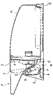
member and with a distal, second end of the spring member engaging a second
member such
that the spring member biases the first and second members relative to each
other. The
spring member has an unbiased condition and is resiliently deflectable
generally normal to its
longitudinal to assume deflected conditions from which the spring member
inherently
attempts to return to its unbiased condition. The longitudinal of the spring
member
preferably remains disposed in a flat plane in deflecting of the spring member
between the
unbiased condition and the deflected conditions. The spring member preferably
has, in
cross-section normal to its longitudinal, a shape including two legs disposed
to lie in planes
parallel the flat plane and joined by a bight normal to the flat plane.
Preferably, the spring
member is provided with resiliency substantially by the resilient deflection
of opposed
portions of the two legs towards and/or away from each other normal to the
flat plane. The
spring member preferably consists of plastic material and may be formed as an
integral
element injection molded from plastic as a unitary element together with the
first member to
which it is coupled.
[0010] The present invention further provides a dispenser of flowable
materials
comprising a support member, an actuator, a member reciprocally movable
relative the
support member between an extended position and a retracted position to
dispense the
flowable material, and a spring mechanism comprising a spring member biasing
the actuator
member to one of the extended position and the retracted position wherein the
spring
mechanism comprises an elongate cantilevered spring member extending along a
2
CA 02505812 2005-04-29
longitudinal coupled at a first end to a first of the support member and the
actuator member
and with a distal, second end engaging the other, second of the support member
and the
actuator member. Preferably, the spring member together with the first of the
presser
member and the support member comprises a unitary element injection molded
from plastic
as a unitary element. Preferably, the spring mechanism comprises two identical
spring sets,
spaced from each other.
[0011] In one aspect, the present invention provides a dispenser for flowable
materials
comprising:
[0012] a support member,
[0013] an actuator member member reciprocally movable relative to the support
member
between between an extended position and a retracted position to dispense
flowable
material,
[0014] a spring mechanism comprising a spring member biasing the actuator
member to
one of the extended position and the retracted position,
[0015] the spring member comprising an elongate cantilevered spring member
extending
along a longitudinal coupled at one first end to a first of the support member
and the actuator
member and with a distal, second end engaging the other, second of the support
member and
the actuator member.
[0016] In another aspect, the present invention provides a dispenser for
flowable
materials comprising:
[0017] a support member,
[0018] an actuator member reciprocally movable relative to the support member
between
an extended position and a retracted position to dispense flowable material,
[0019] a spring mechanism biasing the actuator member to one of the extended
position
and the retracted position,
[0020] a spring mechanism comprising a first spring member and a second spring
member,
3
CA 02505812 2005-04-29
[0021] the first spring member comprising an elongate cantilevered leaf spring
member
extending along a longitudinal of the first spring member from a first end
thereof which
merges into the support member toward the actuator member to a distal second
end thereof,
[0022] the first spring member having an unbiased condition and being
resiliently
deflectable generally normal to its longitudinal to deflected conditions from
which the first
spring member inherently attempts to return to its unbiased condition,
[0023] the second spring member comprising an elongate cantilevered leaf
spring
member extending along a longitudinal of the second spring member from a first
end thereof
which merges into the actuator member toward the support member to a distal
second end
thereof,
[0024] the second spring member having an unbiased condition and being
resiliently
deflectable generally normal to its longitudinal to deflected conditions from
which the
second spring member inherently attempts to return to its unbiased condition,
[0025] the first spring member proximate the distal end thereof engaging the
second
spring member proximate the distal end thereof to interact as a combined
double leaf spring.
Brief Description of the Drawings
[0026] Further aspects and advantages of the present invention will become
apparent
from the following description taken together with the accompanying drawings
in which:
[0027] Figure 1 is a schematic rear perspective view showing a dispenser in
accordance
with the first embodiment of the present invention with an assembled
dispensing unit in the
process of being mounted to a wall plate;
[0028] Figure 2 shows a schematic pictorial rear and side view of the
dispenser of Figure
1 from above with the dispensing unit fully mounted on the wall plate;
[0029] Figure 3 shows a schematic pictorial rear and side view of the
dispenser of Figure
2 from below;
[0030] Figure 4 shows a pictorial bottom and front view of the bottle of the
dispenser of
Figure 1 from below;
[0031] Figure 5 is a pictorial bottom and rear view of the bottle of Figure 4
from below;
4
CA 02505812 2005-04-29
[0032] Figure 6 is a pictorial bottom view of the bottle of Figure 4;
[0033] Figure 7 is a pictorial front view of the wall plate of the dispenser
of Figure 1;
[0034] Figure 8 is a pictorial top view of the dispenser as shown in Figure 1
with the
bottle in the position of being inserted onto the wall;
[0035] Figure 9 is a pictorial view of a piston member used in the embodiment
of Figure
1;
[0036] Figure 10 is a pictorial view of a piston chamber forming element used
in the
embodiment of Figure 1;
[0037] Figure 11 is a pictorial view of an assembled pump mechanism formed by
assembly of the piston member of Figure 9 and the piston chamber forming
member of
Figure 10;
[0038] Figure 12 is a pictorial view of the bottle of Figure 4 with the pump
mechanism of
Figure 11 coupled thereto;
[0039] Figure 13 is a pictorial view of the actuator member of the dispenser
of Figure 1
in an open position;
[0040] Figure 14 is a partially cross-sectioned pictorial view of the actuator
of Figure 13
as viewed from the other side of the actuator to that viewed in Figure 13;
[0041] Figure 15 is a pictorial view of the underside of the actuator member
shown in
Figure 13;
[0042] Figure 16 is a pictorial view of the actuator of Figure 13 in a closed
position;
[0043] Figure 17 is a cross-sectional side view of the actuator of Figure 16
as cross-
sectioned adjacent one spring member;
[0044] Figure 18 is a pictorial partially cross-section side view of the
actuator member
shown in Figure 16 in a fully extended position and showing the location of
the pump
mechanism of Figure 11 if the pump mechanism were received within a bottle
coupled to the
actuator member;
[0045] Figure 19 is a view the same as that of Figure 17, however, with the
actuator
member in a retracted position;
CA 02505812 2005-04-29
[0046] Figure 20 is a schematic cross-section pictorial view of the dispenser
shown in
Figure 2 along a central plane vertically through the dispenser;
[0047] Figures 21 and 22 are cross-sectional side views through the pump
assembly and
bottle as shown in Figure 12 through cross-sections coaxial with the neck of
the bottle and
including but a small section of the bottom wall of the bottle;
[0048] Figure 23 is a perspective view of the dispenser in accordance with a
second
embodiment of the present invention fully assembled;
[0049] Figure 24 is a pictorial view of the bottle of the dispenser of Figure
23;
[0050] Figure 25 is a perspective view of a pump used with the dispenser of
Figure 23;
[0051] Figure 26 is a pictorial view of a back plate of the dispenser of
Figure 23;
[0052] Figure 27 is an exploded view illustrating an integral housing member
and presser
member with a removable support plate member for the dispenser of Figure 23;
[0053] Figure 28 is a perspective view of the support member also shown in
Figure 27;
[0054] Figure 29 is a partial perspective view of the unitary housing member
and presser
member shown in Figure 27;
[0055] Figure 30 is an assembled view of the housing member and presser member
with
the support member assembled as seen from the rear;
[0056] Figure 31 is a schematic cross-sectional side view through the
dispenser of Figure
23 showing the bottle in a seated position relative to the housing member;
[0057] Figure 32 is an enlarged cross view of portions of Figure 31;
[0058] Figure 33 is a cross-sectional side view the same as Figure 32,
however, showing
the presser member pivoted inwardly;
[0059] Figure 34 is a cross-sectional side view along section line 8-8' of the
spring
elements in Figure 32;
[0060] Figure 35 is a partially cross-sectioned side view of the opposite side
of the
dispensing assembly to that shown in Figure 31, however, with the bottle in an
unseated
position relative to the housing member ready for movement to a fully inserted
seated
position.
6
CA 02505812 2005-04-29
[0061] Figure 36 is a cross-sectional side view as in Figure 32 but showing
modified
spring members; and
[0062] Figure 37 is a cross-sectional view identical to that in Figure 34,
however,
showing an alternate composite version of a spring member.
Detailed Description of the Drawings
[0063] Reference is made to Figures 1 to 21 which show a first embodiment of a
soap
dispenser 10 comprising a dispensing unit 12 removably coupled to a wall plate
14. The
dispensing unit 1.2 comprises an assembly of a reservoir bottle 20, a piston
pump mechanism
18 and an activator member 16.
Bottle
[0064] The reservoir bottle 20 is best shown in Figures 4 to 6. The bottle 20
has a rear
wall 22, a forward wall 23, two side walls 24 and 25, a top wall 26 and a
bottom wall 27. A
cylindrical externally threaded neck 28 carrying helical threads 29 extends
downwardly from
the bottom wall 27 and provides an exit opening 30 for communication with the
interior of
the bottle.
[0065] The neck 28 also carries an annular flange 31 spaced a uniform distance
from the
bottom wall 27 so as to provide an annular slotway 32 therebetween adapted for
coupling the
bottle 20 to the activator member 16.
[0066] The bottom wall 27 has a catch ramp 33 to engage the activator member
16 in a
manner to resist uncoupling of the bottle 20 from the actuator member 16.
[0067] The rear wall 22 of the bottle carries a mounting wedge 34 which has
spaced side
walls 35 and 36, best seen in Figures 6 and 8, which are undercut in the sense
that they
provide laterally inwardly extending slotways 37 and 38 for coupling of the
bottle to the wall
plate 14.
[0068] The configuration of the mounting wedge 34 is preferably adapted to
facilitate
manufacture of the bottle 20 by blow molding from relatively inexpensive
plastic materials
such as polyethylene, preferably low density polyethylene yet provide for
secure coupling of
the bottle 20 to the wall plate 14.
7
CA 02505812 2005-04-29
Wall Plate
[0069] The wall plate 14 is best seen in Figures 7 and 8. The wall plate has a
planar rear
surface 40 for engagement as, for example, with a washroom wall proximate a
sink. The
wall plate 14 may be secured to the wall by known means, preferably, by
adhesives such as
two-sided adhesive tape or fasteners such as screws. Openings 42 to receive
such fasteners
are shown to extend through the wall plate 14.
[0070] The forward surface 43 of the wall plate carries a wedge-shaped slot 44
defined
between two angled shoulder forming members 45 and 46 which each present a
laterally and
inwardly extending catch member 48 and 49 which are adapted to be received in
the slotways
37 and 38 of the bottle 20. The slot 44 is complementary in size and shape to
the mounting
wedge 34 on the bottle.
[0071] The bottle 20 is removably mounted to the wall plate 14 by aligning the
mounting
wedge 34 on the bottle 20 with the groove 44 on the wall plate 14 and sliding
the bottle 20
vertically downwardly. The wall plate 14 preferably carries a resilient
deflectable
cantilevered shoulder carrying latch finger 50 adapted to releaseably lock the
wall plate 14 to
the activator member 16.
[0072] As seen in Figure 8, the mounting wedge 34 on the bottle 20 provides a
dovetail-
like member to be received in the dovetail-like slot 44 in the wall plate 14.
Pump Mechanism
[0073] As seen schematically in Figures 9 to 12, the pump mechanism 18
comprises a
piston chamber forming element 52 and a piston member 53. The piston chamber
forming
element 52 is adapted to be sealably engaged in the exit opening 30 of the
bottle 20 by reason
of an internally threaded flange 54 threadably engaging the threaded neck 28
of the bottle 20
and locating the piston chamber forming element coaxially within the neck 28.
The piston
member 53 is axially slidably received in the piston chamber forming element
52 for axial
sliding therein coaxially between an extended position and a retracted
position to dispense
flowable materials from the bottle 20.
[0074] Figures 21 and 22 show cross-sectional views of a complete pump
mechanism 18
coupled to the bottle 20 shown schematically. The piston chamber forming
element 52
8
CA 02505812 2011-05-16
carries one-way inlet valve 55 via which material in the bottle may pass into
a chamber 139
inside the piston chamber forming element 53. The piston member 53 has an
outlet
extension tube 56 extending outwardly from the piston chamber forming element
52 and
carrying an annular engagement flange 57 for engagement to reciprocally move
the piston
member 53. The piston member 53 has radially outwardly directed flanges 58 to
interact
with the chamber 139 inside the piston chamber forming element 52 so as to
dispense
material out through an outlet passageway 140 centrally through the outlet
extension tube 56.
The piston pump mechanism 18 preferably includes a resilient air relief valve
142 to permit
air to enter the bottle 20 to replace material dispensed as when vacuum
conditions are created
inside the bottle 20 which is preferably configured to be rigid or
substantially non-
collapsible.
[0075] The pump mechanism illustrated is of a type similar to that disclosed
in the
applicant's U.S. Patent 5,282,522, issued February 1, 1994. Various other
similar piston
pumps may be used as, for example, disclosed in the applicant's U.S. Patent
5,676,277,
issued October 14, 1997 preferably for dispensing liquids and U.S. Patent
6,601,736, issued
August 5, 2003 preferably for dispensing foam liquid. Other similar piston
pump
mechanisms adapted for coupling to the outlet of bottles are well known. It is
preferred to
adopt pump mechanisms which are made entirely out of plastic and do not
incorporate any
metal components. The pump mechanisms may include pump mechanisms which permit
dispensing of more than one component in a dispensing stroke and may dispense
flowable
solid and grit-like materials alone or in combination with paste, liquids or
flowable materials
or foamed liquids. As well, the pump mechanism may provide a nozzle at the end
of the
extension tube 56 which provides for spraying of the fluid dispensed.
Actuator Member
[0076] The actuator member 16 is shown in Figures 13 to 19. The actuator
member 16 in
the preferred embodiment comprises a unitary element preferably injection
molded from
plastic. The actuator member comprises a support member 60 and a presser
member 61
9
CA 02505812 2005-04-29
pivotally coupled together for pivoting about a hinge axis 62 by a living
hinge 63 which is a
thin plate of plastic which bridges between the support member 60 and the
presser member
61. The activator member 16 is shown in Figures 13, 14 and 15 with the support
member 60
and the presser member 61 disposed about the hinge axis 62 in an open
position, being a
position in which the activator member is preferably formed during injection
molding. From
the open position shown in Figures 13 to 15, the actuator member is folded
about the hinge
axis 62 to assume closed, operative positions for dispensing use as shown in
Figures 16 to 19.
[0077] The closed, operative position illustrated in Figures 16 to 19
represent a fully
extended position in Figures 16, 17 and 18 and a retracted position in Figure
19 effectively
showing the relative range of pivoting of the support member 60 and the
presser member 61
in normal operation to dispense fluid.
[0078] As shown in Figure 13, the support member 60 has an open box-like
structure
with a support shelf 64 from which interconnected front wall 65, rear wall 66
and side walls
67 and 68 depend upwardly as shown. Similarly, the presser member 61 has an
open box-
like structure with a support shelf 69 from which interconnected front wall
70, rear wall 71
and side walls 71 and 72 depend upwardly as shown. In the presser member 61,
the front
wall 70 also extends downwardly beyond the shelf 69 as a front wall engagement
portion 73
of a hand lever 74 having side wall portions 75 and 76 which extend downwardly
from the
side walls 71 and 72. A rear wall 77 of the hand lever 74 closes the rear of
the hand lever 74
bridging between the engagement portion 73 and the shelf 69 and between the
side wall
portions 75 and 76.
[0079] As best seen in Figure 16, the support shelf 64 of the support member
60 has an
elongate opening 78 therethrough comprising an enlarged entry portion 79 at a
rear end of
the opening 78 and a smaller snap opening 80 at a forward end of the opening
78. Two
resilient fingers are provided on either side of a rear entranceway to the
snap opening 80.
The snap opening 80 is adapted to be received in the slotway 32 about the neck
28 of the
bottle 20 to couple the bottle 20 to the support member 60 with the resilient
fingers 81 to
deflect outwardly to permit the neck 28 of the bottle 20 to enter into the
snap opening 80 and
with the fingers 81 to assume their undeflected condition and maintain the
neck 28 of the
CA 02505812 2005-04-29
bottle securely and fixedly received within the snap opening 80 and with the
bottom wall 77
of the bottle 20 supported on the support shelf 64.
[0080] In assembly of the dispensing unit 12, the piston pump mechanism 18 is
coupled
to the bottle 20 by threadably engaging the piston chamber forming element 52
onto the
threaded neck 28 of the bottle with the piston member 53 received in the
piston chamber
forming element 52. The sub-assembly of the bottle 20 and the pump mechanism
18 is then
coupled to the actuator member 16 by the neck 28 of the bottle carrying the
piston chamber
forming element 53 thereabout being inserted downwardly through the enlarged
entry portion
79 of the opening 78 until the support shelf 64 is in alignment with the
slotway 32 on the
neck 28 between the annular flange 31 and the bottom wall 27 of the bottle.
Subsequently,
the bottle is moved forwardly relative to the support shelf 64 such that the
snap opening 80
engages in the slotway 32 about the neck and securely engages the bottle 20 to
the support
member 60.
Piston Catch Fingers
[0081] The shelf 69 of the presser member 61 carries an elongate opening 83
through
which the nozzle or outlet extension tube 56 of the piston member 53 is to
extend.
[0082] On either side of the opening 83, the shelf 69 carries two resilient
piston catch
fingers 84 and 85 which are to engage the engagement flange 57 of the piston
member 53 to
couple the piston member 53 for movement with the presser member 61. The catch
fingers
84 and 85 carry a downwardly facing catch shoulder 86 and 87 to engage an
upper surface of
the engagement flange 57. The shelf 69 also has two upwardly extending arms 90
and 91 on
either side of the opening 83 presenting arcuate pivot shoulders 88 and 89
adapted to engage
the lower surface of the engagement flange 57. The engagement flange 57 is to
be received
between the catch shoulders 86 and 87 and the pivot shoulders 88 and 89 such
that with
arcuate movement of the presser member 61 relative the support member 60, the
piston
member 53 may slide in linear fashion relative the support member 60 axially
relative the
piston chamber forming element 52.
[0083] The catch fingers 84 and 85 are resilient and adapted to be deflected
away from
each other so as to permit the engagement flange 576 of the piston member 53
to move past
11
CA 02505812 2005-04-29
their distal ends such that after the bottle 20 and pump mechanism 18 have
been secured to
the support member 60, the presser member 61 may be pivoted towards the
support member
61 and the distal ends of the catch fingers 84 and 85 will engage the side or
lower surfaces
144 of the engagement flange 57 and be biased apart such that the catch
fingers 84 and 85
will come to be disposed with their catch shoulders 86 and 87 engaging the
upper surface 143
of the engagement flange 57.
[0084] As best seen in Figure 14, the support member 60 carries on its rear
wall 66 two
inwardly extending hook-like catch members 94 and 95 which are adapted to be
received and
to slide, when the actuator member 16 is in a closed position in two slots 96
and 97 provided
in the rear wall 71 of the presser member 61. Each of these slots 96 and 97
have a blind end
which forms catch members 98 and 99 to engage with the catch members 94 and 95
and
prevent pivoting of the presser member 61 away from the support member 60
beyond a fully
extended position similar to that shown in Figure 17. The catch members 94 and
95 are
resilient such that on initial folding of the actuator member 16 from the open
position to past
the fully extended position, the catch members 94 and 95 will deflect to pass
past the catch
members 98 and 99 and prevent subsequent unfolding of the actuator member 16
past a fully
extended position similar to that shown in Figures 16, 17 and 18.
[0085] Catch members 94 and 95 on the support member 60 engage the catch
members
98 and 99 on the presser member 60 and limit pivoting of the presser member 61
away from
the support member 60 to a fully extended position and thereby against
pivoting to a position
in which the piston member 53 may be withdrawn from the piston chamber forming
member
52.
Spring Member
[0086] Two elongate spring members 100 and 101 are provided on the support
member
60 extending from the support member 60 to the presser member 61 and biasing
the presser
member 61 to pivot about the hinge axis 62 up towards the extended position.
In this regard,
the spring members 100 and 101 are cantilevered leaf spring members carried by
the shelf 64
of the support member 60 and extending from a rear end on the shelf 64
forwardly and away
from the shelf 64 such that the spring members 100 and 101 extend out of the
plane of the
12
CA 02505812 2005-04-29
shelf 64. The spring members have distal second forward ends 102 and 103 to
engage slide
ramps 105 and 106 provided on the presser member 61. The slide ramps provide
slideways
107 and 108 between two upstanding locating curbs 109 on each side of each
slideway which
curbs 109 assist in guiding the distal ends 102 and 103 of the spring members
in sliding
longitudinally along the slideways 107 and 108.
[0087] Figure 18 shows a fully extended position in which the distal end 102
of the
spring member 100 engages a forward portion of the slideway 107. Figure 19
shows a
retracted position in which the distal end 102 of the spring member 100
engages a more
rearward portion of the slideway 107 than in Figure 18. In pivoting of the
presser member 61
between the extended and retracted positions, the distal end 102 of the spring
member 100
slides on the slideway 107.
[0088] Each spring member 100 and 101 is elongate about a longitudinal
extending along
the length of the spring member. Each spring member is deflected substantially
normal to its
longitudinal in moving between the extended position and the retracted
position.
[0089] The slideways 107 and 108 are shown to be arcuate and inclined so as to
be
disposed further away from the support member 60 at the forward portion which
the distal
end 102 engages in the extended position than at the more rearward portion
which the distal
end 102 engages in the retracted position. This arrangement with the slotways
being
progressively further from the support member 60 with distance from the
forward end of the
slotway assists in reducing the deflection required of the spring members to
bias the presser
member 61 from the retracted position to the extended position.
[0090] As seen in Figures 14, 15 and 16, each spring member 100 and 101 has an
open
box-like construction with a pair of parallel side wall forming leg members
150 and 151
joined by a bridge wall-like bight 152 and with a cross-section normal the
longitudinal of the
spring member appearing of U-shape. Resiliency is preferably provided to the
spring
members by resilient deflection of opposed portions of the legs 150 and 151
towards and
away from each other.
[0091] The longitudinal of the spring members lies in a plane normal to the
hinge axis 62
and in deflection of the spring members between an unbiased condition and
deflected
13
CA 02505812 2005-04-29
conditions, the longitudinal of the spring member remains disposed in the same
plane normal
to the hinge axis.
[00921 The shelf 64 of the support member 60 has two elongate slots 109 and
110 formed
therein and each of the spring members 100 and 101 as seen disposed
longitudinally above
these slots merging with the support shelf 64 at one end of the slots.
[00931 As best seen in Figure 18, the support member 60 has an opening 111 in
its rear
wall 66 exposing an edge portion 112 of the support shelf 64. This edge
portion 112 serves a
catch surface for engagement by a catch shoulder 113 carried on the latch
member 50 of the
wall plate as seen in Figure 1. On sliding of the assembled dispensing unit 12
downwardly
onto the wall plate 14 with the bottle 20 to engage the wall plate 14, the
latch member 50
snaps into catching engagement on the edge portion 112 to prevent upward
sliding of the
dispensing unit 12 relative to the wall plate 14. The presser member 61 has
its rear wall
extend forwardly inwardly in a central circular portion 113 which provides a
vertical
passageway 114 upwardly from the bottom of the presser member 61 for a
person's finger to
engage the latch member 50 and to displace it rearwardly to permit removal of
the dispensing
unit 12 from the wall plate 14 by upward sliding. Reinforcement of the support
shelf 64 of
the support member 60 proximate the edge portion 112 is provided by an
upstanding
downwardly extending semi-circular reinforcement flange 115 provided about the
rear
periphery of the opening 78.
[0094) In insertion of a bottle 20 onto the support shelf 64 of the support
member 60, the
catch ramp 33 on the bottom wall 27 of the bottle 20 is cammed and deflect the
bottom wall
47 of the bottle upwardly as the bottle moves forwardly over the edge portion
112 until the
catch ramp 33 becomes fully disposed within the rear portion 79 of the opening
78 at which
point in time the catch ramp 33 snaps downwardly into the opening 78. As best
seen in
Figures 12 and 13, the catch ramp 33 has a forward, inclined ramping surface
116 and an
arcuate vertical rear surface 117. Engagement between the rear surface 117 and
the
reinforcement flange 115 about the rear of the elongate opening 78
substantially prevents the
bottle from being removed from engagement with the support member 60, at least
without
folding the actuator member 16 to an open position to access and forcibly
direct the bottom
14
CA 02505812 2005-04-29
wall 27 of the bottle 20 away from the support shelf 64. The rear surface 117
of the catch
ramp 33 has a curved shape complementary to the curved shape of the rear of
the opening 78
and its reinforcing flange 115. This serves to accurately locate and center
the bottle 20
relative to the support member 60 and to prevent relative pivoting of the
bottle 20 or relative
sideways movement of the bottle 20 relative to the support shelf 64.
[0095] The preferred embodiment of the actuator member 16 illustrated in
Figures 1 to
22 is preferably injection molded as a unitary element from relatively low
cost plastic,
preferably low density polyethylene. It is to be appreciated therefore that
each of the
elements forming the actuator member 16 are formed as an integral part
thereof. The spring
members 100 and 101 are particularly configured to provide adequate resiliency
notwithstanding that inexpensive plastic such as low density polyethylene may
be used.
Such plastics are known to have poor resiliency in elasticity and to become
permanently
deformed through repeated bending and deflection or deformation.
[0096] The dispenser unit 12 can be adapted for use as a single use disposable
unit which
will be discarded once the material inside the bottle 20 has been dispensed. A
typical bottle
size is in the range of 0.5 to two litres and, typically, fluid is dispensed
in allotments in the
range of about 0.5 ml to 2 ml. Thus, for example, with a one litre bottle and
0.5 ml
allotments, the spring members need to be capable of enduring about 2,000
cycles before
they may fail. The spring members may preferably be designed so as to fail
after a certain
number of cycles as, for example, 25% or 50% or 100% more cycles than required
to
dispense fluid from a particular bottle so as to prevent re-use of the single
use dispensing
unit.
[0097] The dispensing unit 12 which may be used as a single use disposable
dispensing
unit preferably is made from as few components as possible in order to reduce
its cost.
Accordingly, the actuator member 16 is being provided as a unitary element
incorporating as
part thereof the spring members, the living hinge, piston catch members and
the other various
elements. It is to be appreciated, however, that while the actuator member 16
is preferably a
unitary element in accordance with the present invention, it may comprise a
plurality of
components. For example, rather than provide a living hinge 63 as shown in the
preferred
CA 02505812 2005-04-29
embodiment, the support member 60 and the presser member 61 may be
substantially
identical to that as illustrated in Figures 1 to 22 but as two separate
elements with each
having complementary hinge forming elements which would permit each of the
support
member 60 and presser member 61 to be formed as separate elements and, for
example, snap
fitted together by their hinge forming elements to form a hinge therebetween.
[0098] The spring members preferably form an integral part of one of the
support
member 60 or presser member 61, however, this is not necessary and separate
spring
members could be provided. For example, one or more helical metal coil springs
to be
disposed between the support member 60 and the presser member 61 to bias them
apart.
Such separate spring members could be used either in embodiments where the
support
member 60 and the presser member 61 are a unitary element joined together by a
living hinge
or are separate elements.
[0099] The spring members 100 and 101 have been illustrated as coupled to the
support
member with a distal end engaging the presser member 61. It is to be
appreciated that this
could be reversed and the spring members could be provided coupled to the
presser member
61 with distal ends of the spring members to engage the support member 60.
[0100] The preferred integral plastic spring members 100 and 101 are shown to
extend
with their longitudinal in a plane normal to the hinge axis 62. This is not
necessary and
similar elongate cantilevered leaf spring members could be provided which
extend in other
directions as, for example, to extend perpendicular to the direction in which
the spring
members are shown in the preferred embodiment.
[0101] Each of the support member 60 and the presser member 61 are provided to
have a
clam shell or box-like construction including a shelf and upstanding wall such
that when the
actuator member 16 is closed, an overlapping closed shell or box is provided
which is closed
and substantially encloses in an enclosed chamber defined therein the spring
members, piston
catch members and piston member. This is advantageous to prevent manual access
inside the
closed chamber and serves to enhance the feature that the dispensing unit,
once assembled,
cannot be disassembled or at least resists disassembly. In this regard, the
bottle 20 by reason
of its catch ramp 33 becoming engaged in effectively a snap fit within the
opening 78 of the
16
CA 02505812 2005-04-29
shelf 64 of the support member 60 substantially prevents the bottle after it
has been coupled
to the support member 60 from being removed. The actuator member 16, once it
has been
closed, resists being unfolded to an open position by reason of the catch
members 94 and 95
on the support member 60 engaging the catch members 98 and 99 on the presser
member 61.
Thus, once the dispensing unit 12 is assembled to form an assembly of the
bottle 20, pump
mechanism 18 and actuator member 16 the dispensing unit 12 substantially
cannot be
disassembled or at least resists disassembly.
[01021 The dispensing unit 12 of the preferred embodiment of Figures 1 to 22
is
configured such that it must be in an assembled condition before it can be
coupled to the wall
plate 14.
[01031 While the dispensing unit 12 is coupled to the wall plate 14, the
dispensing unit
cannot be disassembled. In this regard, in order for the bottle 20 to be
removed from the
support plate 60, it is necessary that the support plate 60 slide horizontally
rearwardly
relative to the bottle. However, with the bottle 20 coupled at its rear to the
wall plate 14,
with the wall plate 14 extending from the bottle 20 downward immediately
rearwardly of the
support member 60, the wall plate 14 prevents rearward movement of the support
member
60.
[01041 In the first embodiment, the assembled dispensing unit 12 is coupled to
the wall
plate 14 by the rear of the bottle 20 engaging the wall plate. In accordance
with a modified
form of the invention, the actuator member 16 and, particularly, the support
member 60
thereof may also engage the wall plate 14 as, for example, by the rear wall of
the support
member 60 carrying its own mounting wedge similar to that provided on the
bottle to be
received in another wedge-shaped slot to be provided on the wall plate 14.
Since the support
member 60 and the wall plate 14 are to be formed by injection molding, a
greater choice of
coupling mechanisms for preferably slidably coupling of the support member 60
to the wall
plate 14 may be provided.
[01051 In accordance with further embodiments of the invention, rather than
having the
bottle 20 coupled to the wall plate 14, merely the support member 60 may be
coupled to the
wall plate 14 for mounting of the dispensing unit 12 to the wall plate 14.
17
-- - ----------- -
CA 02505812 2005-04-29
[01061 The preferred bottle 20 is a substantially, non-collapsible,
substantially rigid
bottle formed by blow molding. This is preferred, however, the bottle could
comprise a
collapsible bottle or bag, however, since the appearance of a collapsing
bottle or bag is
generally considered to be unappealing, the use of a collapsible bottle or bag
would likely
require the provision of a housing about the collapsible bottle or bag which
is undesirable in
respect of cost and may render the dispensing unit more susceptible to
disassembly.
[01071 The preferred embodiment of the dispensing unit 12 provides for the
bottle 20 to
be an enclosed container as is advantageous for shipment with the assembled
dispensing unit
12 inverted. The bottle 20 preferably is vented through the pump mechanism 18
in use with
air to be introduced into the bottle to replace material dispensed. This is
not necessary and
the bottle 20 may be provided with a suitable vent hole or port open in its
top wall to the
atmosphere.
[01081 The preferred embodiment illustrates the dispenser unit 12 as being
arranged with
a bottle inverted for gravity feed of material in the bottle to the piston
pump mechanism for
dispensing from the opening 30 disposed at the bottom of the bottle. This is
preferred but not
necessary and various inverted versions of the dispensing unit could be
provided for use with
piston pump mechanisms having a feed tube extend downwardly into a bottle from
a piston
pump mechanism disposed at an opening disposed at the top of the bottle and
with a nozzle
from the piston member 52 extending forwardly over the presser member 61 and
then
downwardly.
[0109] The bottle 20 is preferably blow molded from inexpensive plastic
material
preferably low density polyethylene so as to provide an inexpensive bottle.
The functional
features of the bottle 20 have been selected having regard to the nature of
this plastic material
from which it is preferably made. Difficulties are typically experienced in
blow molding
complex structures into bottles when low cost plastics are used. The preferred
bottle has
been selected to have a configuration particularly with the mounting wedge 34
configured to
be a relative shape and size which can be formed by inexpensive blow molding
techniques
commonly used.
18
CA 02505812 2005-04-29
[01101 Reference is now made to the second embodiment of a dispenser in
accordance
with the present invention as illustrated in Figures 23 to 37. In the second
embodiment,
similar reference numerals are used to refer to elements similar to elements
in the first
embodiment. The second embodiment also shows a soap dispenser comprising a
dispensing
unit 12 adapted to be removably coupled to a wall plate 14 shown in Figure 26.
The
dispensing unit 12 comprises an assembly of a reservoir bottle 20 shown in
Figure 24, a
piston pump mechanism 18 shown in Figure 25 and, a housing 118. The housing
118 is
formed as an integral member having a housing member 119 joined by a living
hinge 63 to a
presser member 61 for relative pivoting about a hinge axis 62 as seen in
Figure 27. A
support member 60 is removably secured to the housing member 119 to be
securely received
therein as, for example, to be assembled as illustrated in rear pictorial view
in Figure 30 and
in side view in Figure 31 with a front edge of a support shelf 64 being
received in a support
slotway 120 on a front wall 121 of the housing member 119 and with a lowermost
portion
122 of each side wall 123 and 124 of the support member 60 received in support
channels
125 and 126 provided at the rear lower edge of the side walls 127 and 128 of
the housing
member 119. The side walls 127 and 128 also carry latch channels 129 and 130
adapted to
receive latch protuberances 131 and 132 carried on the side walls 123 and 124
of the support
member 60 preventing rearward removal of the support member 60 other than by
biasing the
side walls 127 and 128 of the housing member 119 apart. When the support
member 60 is
assembled to the housing member 119, the support member 60 is effectively
fixedly secured
to the housing member 119 against relative movement and provides a housing sub-
assembly.
[01111 For use, the wall plate 14 is adapted to be secured to a wall. The
housing sub-
assembly is then coupled to the wall plate 14. The reservoir bottle 20 with
the piston pump
mechanism 18 pre-attached thereto as a bottle sub-assembly is coupled to the
housing sub-
assembly by the bottle sub-assembly being located in engagement with the
housing 118 in an
unseated position. The unseated position is illustrated in Figure 35, however,
for ease of
illustration, without the pump mechanism 18 attached to the bottle 20, with
the neck 28 of the
bottle 20 extending through the elongate opening 78 of the support shelf 64,
the support shelf
64 becoming received in the slotway 32 on the neck 28 of the bottle 20, and a
rear central
19
CA 02505812 2005-04-29
protuberance 130 at the upper rear of the bottle 20 received within a
downwardly opening
access opening 132 of a recess 134 provided at an upper rear of the housing
member 119.
From this unseated position as illustrated in Figure 35, the lower end of the
bottle 20 may be
urged rearwardly effectively pivoting the bottle 20 about an effective fulcrum
where the
protuberance 130 engages the front of the access opening 132 such that the
bottle 20 moves
rearwardly in a pivoting motion to a seated position as illustrated in Figure
31.
[0112] With such an insertion of the bottle sub-assembly in a similar manner
of that
described with reference to the first embodiment, two resilient piston catch
fingers 84 and 85
carried on the presser member 61 engage the engagement flange 57 of the piston
member 53
to couple the piston member 53 for movement with the presser member 61. In a
similar
manner to that described with the first embodiment, the engagement flange 57
comes to be
engaged between the piston catch fingers 84 and 85 with an upper surface of
the engagement
flange 57 engaged by the downward facing catch shoulders 86 and 87 of the
fingers and with
a lower surface of the engagement flange 57 to be engaged by spaced arcuate
pivot shoulders
88 and 89. In the second embodiment, the resilient piston catch fingers 84 and
85 are
illustrated as being formed of plastic as integral elements to the remainder
of the presser
member 61.
[0113] As in the first embodiment, the second embodiment has the support
member 60
carry two elongate spring members 100 and 101 provided on the support member
60 carried
on the shelf 64 and extending from a rear end on the shelf 64 forwardly and
away from the
shelf 64 to distal forward ends 102 and 103. However, in the second
embodiment, the
presser member 61 also carries two elongate spring members 160 and 161 carried
by the
shelf 69 of the presser member 61 and extending from a forward end of the
shelf 69
rearwardly and upwardly away from the shelf 69 such that the spring members
160 and 161
extend out of the plane of the shelf 69. The spring members 160 and 161 have
distal second
forward ends 162 and 163 to engage the distal forward ends 102 and 103 of the
spring
members 100 and 101 provided on the support member 60. As seen in Figure 30,
the spring
members 160 and 161 are provided outwardly from each of the piston catch
fingers 84 and
85.
CA 02505812 2005-04-29
[0114] As seen in Figure 30, the presser member 61 carries on its rear wall 71
two
rearwardly extending hook-like catch members 94 and 95 which are adapted to be
received in
two slots 96 and 97 provided in the rear wall 66 of the support member 60.
Each of the slots
96 and 97 have a blind end to engage with the catch members 94 and 95 on the
presser
member 61 and prevent pivoting of the presser member 61 away from the support
member
60 beyond a fully extended position shown in Figures 31 and 32. From the
extended position
of the presser member 61 relative to the support member 60 shown in Figures 31
and 32, the
presser member 61 may be pivoted about the hinge axis 62 to a retracted
position as
illustrated in Figure 33. Reciprocal movement in a cycle between the extended
position of
Figure 32 and the retracted position of Figure 33 will move the piston member
53 of the
pump mechanism 18 and dispense fluid from the bottle 20. In the range of
movement
between the extended position shown in Figure 32 and the retracted position
shown in Figure
33, the spring members 100 and 101 on the support member 60 engage the spring
members
160 and 161 on the presser member 61 and bias the presser member 61 to pivot
about the
hinge axis 62 towards the extended position.
[0115] Reference is made to Figure 34 which illustrates a cross-sectional side
view
through the spring members 100 and 160 along section lines 8-8' in Figure 32.
As seen, the
spring member 100 has an elongate web 152 and a pair of parallel flanges or
leg members
150 and 151 extending normal to the web 152. The spring member 160 of the
presser
member 61 similarly have an elongate web 164 and three parallel leg members
165, 167 and
169 extending normal to the web 164. As seen in cross-section in Figure 34,
the flange-like
legs 150 and 152 of the spring member 100 of the support member 60 are
received in the
channels 166 and 168 between the legs 165, 167 and 169 of the spring member
160
contacting the web 164 therebetween. Similarly, the three legs 165, 167 and
169 of the
spring member 160 engage the web 152 of the spring member 100 on either side
of the legs
150 and 151. The legs 150 and 151 on the spring member 100 effectively form
with the
portion of the web 152 therebetween a U-shaped member. Any two of the legs
165, 167 and
169 with the web 164 therebetween also form a U-shape member on spring member
160.
The nesting of a leg of one spring member in the channel between the legs of
the other spring
21
CA 02505812 2005-04-29
member provide an advantageous structure such that the opposed spring members
100, 101
which engage the spring members 160, 161, respectively, will be maintained
longitudinally
of each other with displacement prevented of any one of the spring member
laterally relative
another opposite spring member that they will not become disengaged from each
other.
[0116] As seen in side view in Figures 32 and 33, the extent to which any one
of the
flange-like legs 150, 151, 165, 167 and 169 extend from their respective webs
152 and 164 is
greatest at a first end of the respective spring member where it is coupled to
its respective
support member 60 or presser member 61 and decreases towards its remote distal
end. This
is believed to be advantageous to distribute the locations where the spring
members may
resiliently deform.
[0117] The spring members preferably have a U-shape in cross-section with the
legs
perpendicular to the web. It is to be appreciated that other shapes such as T-
shapes, L-shapes
and the like are suitable in providing a beam with resistance to deflection
both in the
common plane and laterally. Any one of the two opposing beam member needs to
have
resistance to deflection laterally when the beams nest or otherwise engage
each other to
prevent relative lateral deflection. The legs do not need to extend parallel
to the common
plane and may, for example, extend laterally to the side at an angle as, for
example, with a V-
shape.
[0118] The beam members illustrated have a contact side-to-side width along
their
length. This is not necessary and the width may vary in distance from the
first end.
[0119] Deformation of a spring member preferably occurs, at least in part, by
deflection
of the legs of the spring member inwardly and outwardly towards or away from
legs on the
same spring member, that is, sideways as seen in Figure 34.
[0120] Each spring member extends longitudinally about a longitudinal axis.
The
longitudinal axis is schematically illustrated respectively as 170 and 171 for
the spring
member 100 and 160 in Figure 34 and extending the length of each spring member
100, 160
centrally along its respective web 152, 164. In deflection of each of the
spring members, the
spring members are resiliently deflectable from an unbiased condition to a
deflected
condition in a direction generally normal to this longitudinal and preferably
in any spring
22
CA 02505812 2005-04-29
member deflecting between the unbiased condition and the deflected conditions
in moving
the longitudinal of the spring member remains disposed in a common, flat plane
illustrated,
for example, as 172 in Figure 34. The flat plane 172 in which the longitudinal
of each spring
member moves preferably is normal to the hinge axis 62.
[0121] As best seen in Figures 32 and 33, each of the webs 152 and 164 of the
spring
members 100 and 160 extend from their respective first end as a relatively
curved portion
merging into a relatively straight portion proximate their distal end. The
straight portions of
the opposed spring members overlap where there is engagement between the
opposed spring
members and with pivoting of the presser member 61 relative to the support
member 60, the
straight portions of each of the opposed spring members are permitted to slide
longitudinally
relative each other.
[0122] In the second embodiment in accordance with Figures 23 to 36, the
presser
member 61 including the spring members 160 and 161 is formed as integral
member from
plastic as by injection molding.
[0123] Reference is made to Figure 36 which is a cross-section identical to
that
illustrated in Figure 32, however, modified from that shown in Figure 32 such
that each the
spring member 100 carried on the support member 60 and the spring member 160
carried on
the presser member 61 extend rearwardly. This is to be contrasted with Figure
32 in which
one spring member extends forwardly to its distal end and the other extends
rearwardly to its
distal end. Similarly, both of the opposed spring members may be provided such
that their
distal ends extend forwardly. Selection of the location of the spring members
and the
direction in which they extend may be made having regard to the other elements
and features
which are to be desired to be provided on the support member and the presser
members on
which the spring members are to be supported.
[0124] The first embodiment of Figures 1 to 22 illustrate elongate
cantilevered spring
members 100 and 101 provided on the support member 60 to engage engagement
ramps 107
and 108 on the presser member 61. An arrangement similar to that illustrated
in the first
embodiment, notably in Figure 13, could be modified so as to provide, in
replacement of the
23
CA 02505812 2005-04-29
engagement surfaces 107 and 108, a second set of spring members on the presser
member 61
similar to the spring members 160 and 161 in the second embodiment.
[0125] In the second embodiment, two pairs of spring mechanism are provided,
each pair
comprising a spring member carried on the presser member 61 to engage another
spring
member provided on the support member 60. Each of the spring mechanisms is
adapted to
have their elongate spring members extend along a longitudinal and to deflect
with their
longitudinal maintained in a common flat plane perpendicular to the hinge axis
62 with each
of the common planes spaced from each other along the spring axis 62 and
disposed to reside
on opposite sides of the neck of the bottle 20.
[0126] The second embodiment of Figures 23 to 37 illustrates, as in Figure 30,
a housing
sub-assembly formed from two parts from the support member 60 and the housing
118
consisting of the housing member 119 and the actuator member 61. It is to be
appreciated
that a not dissimilar housing sub-assembly could be formed, if desired, as a
unitary part of
plastic by injection molding as in the manner of the actuator 16 shown in
Figure 13, however,
with an upwardly extended rear wall portion.
[0127] The preferred embodiments illustrate the spring members being formed as
integral
elements with the presser member 61 or support member 60 from which they
depend. This is
not necessary and is to be appreciated that, while not typically preferred,
each of the spring
members could be provided as a separate element to be received, for example,
in a suitably
strong socket as in a sliding manner or the like on their, for example,
respective presser
member 61 or support member 60.
[0128] The cantilevered spring members need not be made from plastic material
but be
made, while considered to be less preferred, from other materials including
spring metal,
preferably, continuing to have a similar shape as to the webs and legs.
Whether or not the
spring members may be formed from plastic or from other materials such as
metal, the
construction of the spring member to extend along this longitudinal, adapted
to deflect
normal to the longitudinal and including the web having legs extending away
from the web,
preferably perpendicular thereto and parallel to its longitudinal, is an
advantageous
configuration. Providing the spring members to be separate elements which are
removable
24
CA 02505812 2005-04-29
can have the advantage of permitting different plastic or other materials to
be used to form
the spring members.
[0129] The spring members may comprise a composite of a plastic member,
preferably
integrally formed with the presser member 61 or support member 60 from which
it depends,
together with a metal spring member. In this regard, Figure 37 shows a
modified cross-
section to that illustrated in Figure 34 in which each spring member 100 and
160 have an
elongate channel 172 or 173 disposed along the length of this web 152 and 164
and adapted
to receive a flat thin piece of spring metal 174 or 175 which has an inherent
tendency to
assume a preset configuration. Such a composite plastic and metal spring
member may be
advantageous to ensure that the plastic spring will maintain operative
characteristics as, for
example, under temperature conditions beyond that normally to be experienced
in heated and
air conditioned work and living premises.
[0130] Each of the first and second embodiments show use of a living hinge to
couple the
presser member 61 to another element to permit relative pivoting. This is
advantageous but
is not necessary. For example, the presser member 61 and living hinge 63
illustrated in both
embodiments may be replaced by a separate presser member which is adapted to
be coupled
as by a hinge including, for example, axle members for pivoting relative to
the element to
which the presser member is coupled.
[0131] The preferred embodiments illustrate the use of preferred spring
members in
accordance with the present invention in a context where they are to bias
apart two elements
which are pivotally mounted for pivoting relative to each other. This is not
necessary and it
is to be appreciated that similar spring members to those illustrated could be
utilized as for
biasing apart members which are to slide linearly or otherwise move relative
to each other
between two positions. For example, a presser member could be provided coupled
to a
piston directly for reciprocal movement as a slide member parallel to the
movement of the
piston and with suitable spring members in accordance with the present
invention provided to
bias such a slide member.
[0132] Whether or not living hinges are used to provide hinge mechanisms, in
accordance with the present invention, a dispensing apparatus can be formed
entirely with
CA 02505812 2005-04-29
plastic as, for example, as illustrated in the second embodiment in which the
spring members
100, 101 and 160, 161 as well as the piston catch fingers 84 and 85 are formed
together with
the remainder of the actuator member 61 as a unitary element of plastic formed
as by
injection molding.
[01331 While the invention has been described with reference to preferred
embodiments,
many modifications and variations will now occur to a person skilled in the
art. For a
definition of the invention, reference is made to the following claims.
26