Note: Descriptions are shown in the official language in which they were submitted.
CA 02506250 2005-05-25
f
v
-1-
SYSTEM AND METHOD FOR PROVIDING REA
MODEL BASED SECURITY
BACKGRO'CJND OF THE TNVENTION
The present invention is related to Resource
Event-Agent (REA) models, and to systems and
methods using an REA model. More particularly, the
present invention is related to a method of
providing security in REA models.
Business users and application developers
prefer software applications where primary
abstractions are the concepts that business people
use to describe their work. For example, the
concepts such as economic resources, business
partners, contracts, and agreements are natural for
business users, while the concepts such as classes,
methods, virtual collections, and fields are
natural for programmers, but not far business
users.
The current trend towards model driven
2o development is an attempt to move away from low
level programming, towards modeling based on the
concepts of the domain experts. Before one can do
any modeling, regardless cf whether this model is
expressed in code or in a diagram, it is desirable
to choose an ubiquitous language that can serve as
the language for all people that work with this
model. This language would stand the test of time
during development and use of the software. An
important aspect to ensuring that the language is
3o reliable and comprehensive enough to fulfill these
requirements is to base the language on a sound
CA 02506250 2005-05-25
t' ,
e. ,
-2-
foundation. One modeling language which provides a
sound foundation to address these needs is REA.
REA is the name of a prescriptive accounting
model introduced by William E. McCarthy in 1982.
See for example, William E. McCarthy, The REA
Accounting- Model: A Generalized Framework for
Accounting Systems in a Shared Data Environment,
The Accounting Review, Vol. LVII, No. 3, 3uly 1982.
REA is often referred to as a model, a framework,
l0 an ontology, an enterprise information system
architecture, or by other commonly used names. The
fundamental advantage of the REA model is that it
provides a prescriptive model for describing a
business's processes- Around the fundamental
prescriptive model, a whole infrastructure of
additions have been added over the years~in the
form of more specifics on the modeling methodology
itself, incorporation of REA ~in public standards,
etc.
While REA allows for the modeling of
"ownership" or "involvement", it does not typically
address security aspects of business models.
Traditional business applications separate security
specifics from the domain or business application
modeling. Because of this there is very little to
discover when it comes to Security configuration or
Meta data and the security subsystem is often
either missing or implemented in parallel to the
application solution.
Prior solutions to security have typically
been to let developers set up a list of properties
that can or cannot be viewed by roles in the
CA 02506250 2005-05-25
-3-
system. This approach is error prone. Further, this
approach involves very complex implementations,
frequently requiring several days per installation.
Sometimes, this approach is implemented in software
by the developer coding the solution. This makes it
even more difficult to obtain the right security
setup as the users (i.e., system administrators,
etc) are not able to change the settings and define
their own roles/security access.
' SL7MMA,RY OF THE INVENTION
A method of providing Resource-Event-Agent
(REA) model based security includes identifying an
association between a first object and a second
object in an REA model. Then, an association class
is created for the association between the first
object and the second object. The association
class, for example called a Security Policy
Association Class, defines security between the
first object and the second object.
The association class, defined between the
first object and the second object, is an object
having properties. The properties of the
association class object define the security
between the first object and the second object. The
step of creating the association class can further
comprise creating one or more association class
objects having properties, with the properties of
the one or more association class objects defining
security between a first class of objects of which
the first object is a member and a second class of
objects of which the second object is a member. The
second object is a securable object, such as a
CA 02506250 2005-05-25
y ;'
-4-
contract or agreement type object, a commitment
type object, an event type object, or a resource
type object. The first object is of a particular
agent type. A role far a user is defined by the
particular agent type for the first object.
The association class created between the
first object and the second object can be created
in a security model either separate from the REA
model, or as part of the REA model. The security
defined between the first object and the second
object includes defining permissions and rights of
the. first object relative to the second abject.
These permissions and rights can be determined
dynamically in a security policy logic module
outside of the security model. This is particularly
useful for permissions and rights which are
transient in nature, for example depending upon the.
date, time, status of an event, etc.
Other features and benefits that characterize
embodiments of the present invention will be
apparent upon reading the following detailed
description and review of the associated drawings.
BRIEF DESCRIPTION OF THE DRAWINGS
FIG. 1 is a block diagram of one exemplary
environment in which the present invention can be
implemented.
FIG. 2 is a block diagram of a general mobile
computing environment in which the present invention
can be implemented.
FIG. 3 is a block diagram illustrating the
basic REA exchange pattern.
CA 02506250 2005-05-25
-5-
FIG. 4 is a block diagram schematically
illustrating a semantic REA model with major ect
obj
types and association types shown.
FIG. 5-1 is a block diagram illustrating an
internal participation association between two
classes of objects in accordance with a
conventional REA model.
FIG. 5-2 is a block diagram illustrating an
internal participation association between two
the
classes of objects shown in FIG. 4-1, with an
association class added in accordance with the
present invention to provide security aspectsto
the model.
FIG. 6-1 is a block diagram illustrating an
external participation association between two
classes of objects in accordance with a
conventional REA model.
FIG. 6-2 is a block diagram illustrating an
external participation association between two
the
classes of objects shown in FIG. 4-1, with an
association class added in accordance with the
present invention to provide security aspectsto
the model.
FIG. 7 is a block diagram illustrating further
aspects of the present invention.
FIG. 8-1 is a block diagram illustrating an
REA based security system in which the security
model with association classes uses the REA
model
semantic information, but exists outside the REA
model itself.
FIG. 8-2 is a block diagram illustrating an
REA based security system in which the security
CA 02506250 2005-05-25
:.
-s-
model with association classes is integrated into
the REA model.
FIG. 9 is a block diagram illustrating a
method of the present invention.
DETAILED DESCRIPTION OF ILLUSTRATIVE EMBODIMENTS
The Resource-Event-Agent (REA) model allows
for the modeling of- "ownership" or "involvement",
but REA modeling semantics have not been used to
drive security configurations. The present
invention is based in part upon the recognition
that REA modeling semantics can be used to provide
such security. Disclosed is a strategy of using the
REA semantics in driving default security
configurations from any REA model incorporating
these semantics. This strategy is used in the
methods and apparatus of the present invention.
Traditional business applications separate
security specifics from the domain or business
application modeling_ In contrast to the security
implementing methods used in these traditional
business applications, using the strategy disclased
herein, REA modeling techniques can be used to
build security information into a domain or
business solution. As used herein, the term
"semantic model" refers to a computer software
model of real-world activities, for example supply
chain activities. A semantic model is rich in
content and describes classes of objects,
relationships, and functions involved in the real-
world activities it models. The REA semantic model
can be expressed in many formats: the eXtensible
Markup Language (XML), the Universal Modeling
CA 02506250 2005-05-25
..~
~.
_7_
Language (UML), a relational database, and/or an
object oriented programming language. In the
following discussions, security implementing
improvements on the REA model are described
primarily in terms of UML, but the present
invention is not limited to UML implementations.
FIG. 1 illustrates an example of a suitable
computing system environment 100 on which the
invention may be implemented. The computing system
l0 environment 100 is only one example of a suitable
computing environment and is not intended to
suggest any limitation as to the scope of use or
functionality of the invention. Neither should the
computing environment 100 be interpreted as having
any dependency or requirement relating to any one
or combination of components illustrated in the
exemplary operating environment 100.
The invention is operational with numerous
other general purpose or special purpose computing
system environments or configurations. Examples of
well known computing systems, environments, and/or
configurations that may be suitable for use with
the invention include, but are not limited to,
personal computers, server computers, hand-held or
laptop devices, multiprocessor systems,
microprocessor-based systems, set top boxes,
programmable consumer electronics, network PCs,
minicomputers, mainframe computers, distributed
computing environments that include any of the
above systems or devices, and the like.
The invention may be described in the general
context of computer-executable instructions, such
CA 02506250 2005-05-25
_g_
as program modules, being executed by a computer.
Generally, program modules include routines,
programs, objects, components, data structures,
etc. that perform particular tasks or implement
particular abstract data types. The invention may
also be practiced in distributed computing
environments where tasks are performed by remote
processing devices that are linked through a
' communications network. In a distributed computing
l0 environment, program modules may be lacated in both
local and remote computer storage media including
memory storage devices.
With reference to FIG. 1, an exemplary system
for implementing the invention includes a general
purpose camputing device in the farm of a computer
110. Components of computer 110 may include, but
are not limited to, a processing unit 120, a system
memory 130, and a system bus 121 that couples
various system components including the system
memory to the processing unit 120. The system bus
121 may be any of several types of bus structures
including a memory bus or memory controller, a
peripheral bus, and a local bus using any of a
variety of bus architectures. By way of example,
and not limitation, such architectures include
Industry Standard Architecture (ISA) bus, Micro
Channel Architecture (MCA) bus, Enhanced ISA (EISA)
bus, Video Electronics Standards Association (VESA)
local bus, and Peripheral Component Interconnect
(PCI) bus also known as Mezzanine bus.
Computer 110 typically includes a variety of
computer readable media. Computer readable media
CA 02506250 2005-05-25
-9-
can be any available media that can be accessed by
computer 110 and includes both volatile and
nonvolatile media, removable and non-removable
media. By way of example, and not limitation,
5 computer readable media may comprise computer
storage media and communication media. Computer
storage media includes both volatile and
nonvolatile, removable and non-removable media
implemented in any method or technology for storage
10 of information such as computer readable
instructions, data structures, program modules or
other data. Computer storage media includes, but is
not limited to, R.AM, ROM, EEPROM, flash memory or
other memory technology, CD-ROM, digital versatile
15 disks (DVD? or other optical disk storage, magnetic
cassettes, magnetic tape, magnetic disk storage or
other magnetic storage devices, or any other medium
which can be used to store the desired information
and which can be accessed by computer 110.
20 Communication media typically embodies computer
readable instructions, data structures, program
modules or other data in a modulated data signal
such as a carrier wave or other transport mechanism
and includes any information delivery media. The
25 term "modulated data signal" means a signal that
has one or more of its characteristics set or
changed in such a manner as to encode information
in the signal. By way of example, and not
limitation, communication media includes wired
30 media such as a wired network or direct-wired
connection, and wireless media such as acoustic,
RF, infrared and other wireless media. Combinations
CA 02506250 2005-05-25
-10-
of any of the above should also be included within
the scope o~ computer readable media.
The system memory 130 includes computer
storage media in the form of volatile and/or
nonvolatile memory such as read only memory (ROM)
131 and random access memory (RAM) 132. A basic
input/output system 133 (BT~S), containing the
basic routines that help to transfer information
between elements within computer 110, such as
during start-up, is typically stored in ROM 131.
RAM 132 typically contains data and/or program
modules that are immediately accessible to and/or
presently being operated on by processing unit 120.
By way of example, and not limitation, FIG. 1
illustrates operating system 134, application
programs 135, other program modules 136, and
program data 137.
The computer 110 may also include other
removable/non-removable volatile/nonvolatile
computer storage media. By way of example only,
FIG. Z illustrates a hard disk drive 141 that reads
from or writes to non-removable, nonvolatile
' magnetic media, a magnetic disk drive 151 that
reads from or writes to a removable, nonvolatile
magnetic disk 152, and an optical disk drive 155
that reads from or writes to a removable,
nonvolatile optical disk 15fi such as a CD ROM or
other optical media. Other removable/non-removable,
volatile/nonvolatile computer storage media that
can be used in the exemplary operating environment
include, but are not limited to, magnetic tape
cassettes, flash memory cards, digital versatile
CA 02506250 2005-05-25
-11-
disks, digital video tape, solid state RAM, solid
state ROM, and the like. The hard disk drive 141 is
typically connected to the system bus 121 through a
non-removable memory interface such as interface
5 140, and magnetic disk drive 151 and optical disk
drive 155 are typically connected to the system bus
121 by a removable memory interface, such as
interface 150.
The drives and their associated computer
10 storage media discussed above and illustrated in
FIG. 1, provide storage of computer readable
instructions, data structures, program modules and
other data for the computer 110.. In FIG. 1, for
example, hard ,disk drive 141 is illustrated as
15 storing operating system 144, application programs
145, other program modules 146, and program data
147. Note that these components can either be the
same as or different from operating system 134,
application programs 135, other program modules
20 136, and program data 137. Operating system 144,
application programs 145, other program modules
146, and program data 147 are given different
numbers here to illustrate that, at a minimum, they
are different copies.
25 A user may enter commands and information into
the computer 120 through input devices such as a
keyboard 162, a microphone 163, and a pointing
device 161, such as a mouse, trackball or touch
pad. Other input devices knot shownl may include a
30 ;oystick, game pad, satellite dish, scanner, or the
like. These and other input devices are often
connected to the processing unit 120 through a user
CA 02506250 2005-05-25
r.
-12-
input interface 160 that is coupled to the system
bus, but may be connected by other interface and
bus structures, such as a parallel port, game port
or a universal serial bus (USB). A monitor 191 or
other type of display device is also connected to
the system bus 121 via an interface, such as a
video interface 190. In addition to the monitor,
computers may also include other peripheral output
devices such as speakers 197 and printer 1.96, which
may be connected through an output peripheral
interface 195.
The computer I10 may operate in a networked
environment using logical connections to one or
more remote computers, such as a remote computer
180. The remote computer 180 may be a personal
computer, a hand-held device, a server, a router, a
network PC, a peer device or other common network
node, and typically includes many or all of the
elements described above relative to the computer
110. The .logical connections depicted in FIG. 1
include a local area network (LAN) 171 and a wide
area network (WAN) 173, but may also include other
networks. Such networking environments are
commonplace in offices, enterprise-wide computer
networks, intranets and the Internet.
When used in a LAN networking environment, the
computer 110 is connected to the LAN 171 through a
network interface or adapter 170. When used in a
WAN networking environment, the computer 110
typically includes a modem 172 or other means for
establishing communications over the WAN 173, such
as the Internet. The modem 172, which may be
CA 02506250 2005-05-25
-I3-
internal or external, may be connected to the
system bus 121 via the user input interface 160, or
other appropriate mechanism. In. a networked
environment, program modules depicted relative to
5 the computer 110, or portions thereof, may be
stored in the remote memory storage device. By way
of example, and not limitation, FIG. 2 illustrates
remote application programs 1.85 as residing on
remote computer 180. It will be appreciated that
10 the network connections shown are exemplary and
other means of establishing a communications link
between the computers may be used.
FIG. 2 is a block diagram of a mobile device
200, which is an alternative exemplary computing
15 environment. Mobile device 200 includes a
microprocessor 202, memory 204, input/output (I/O?
components 205, and a communication interface 208
for communicating with remote computers or other
mobile devices. In one embodiment, the afore-
20 mentioned components are coupled for communication
with one another over a suitable bus 210.
Memory 204 is implemented as non-volatile
electronic memory such as random access memory
(RAM) with a battery back-up module (not shown?
25 such that information stored in memory 204 is not
lost when the general power to mobile device 200 is
shut down. A portion of memory 204 is preferably
allocated as addressable memory for program
execution, while another portion of memory 2G4 is
30 preferably used for storage, such as to simulate
storage on a disk drive.
CA 02506250 2005-05-25
-14-
Memory 204 includes an operating system 212,
application programs 214 as well as an object store
216. During operation, operating system 212 is
preferably executed by processor 202 from memory
5 204. Operating system 212, in one preferred
embodiment, is a WINDOWS~ CE brand operating system
commercially available from Microsoft Corporation.
Operating system 212 is preferably designed for
mobile devices, and implements database features
10 that can be utilized by applications 214 through a
set of exposed application programming interfaces
and methods. The objects in object store 216 are
maintained by applications 214 and operating system
212, at least partially in response to calls to the
15 exposed application programming interfaces and
methods.
Communication interface 208 represents
numerous devices and technologies that allow mobile
device 200 to send and receive information. The
20 devices include wired and wireless modems,
satellite receivers and broadcast tuners to name a
few. Mobile device 200 can also be directly
connected to a computer. to exchange data therewith.
In such cases, communication interface 208 can be
25 an infrared transceiver or a serial or parallel
communication connection, all of which are capable
of transmitting streaming information.
Input/output components 206 include a variety
of input devices such as a touch-sensitive screen,
30 buttons, rollers, and a microphone as well as a
variety of output devices including an audio
generator, a vibrating device, and a display. The
CA 02506250 2005-05-25
-15-
devices listed above are by way of example and need
not all be present on mobile device 200. In
addition, other input/output devices may be
attached to or found with mobile device 200.
5 Review of REA Modeling
REA is an established modeling technique,
ontology and semantic model for describing economic
and business systems. REA describes a business
system as a set of economic Resources, economic
10 Events and economic Agents as well as relationships
among them. Economic Events capture changes of
ownership of economic Resources between ecanomic
Agents. FIG. 3 illustrates the basic REA metamodel
300, having Resources 305, Events 310 and Agents
15 315.
In the REA model, the exchanges of economic
Resources are the primary economic data about the
enterprise. Accounting artifacts such as debit,
credit, journals, ledgers, receivables and accounts
20 are derived from the data describing the exchanges.
For example, the quantity an hand for an inventory
item can be calculated as the imbalance between the
Purchase Events and the Sale Events for that
inventory item. In comparison, in most current
25 Enterprise Resource Planning (ERP) systems it is
opposite - the economic data is derived from the
accounting artifacts. This, in some sense, puts the
consec_ruence before the cause and makes the model
more complicated.
30 In addition, REA contains rules (axioms)
assuring consistency of the model from an economic
perspective. As the result: (1) The REA models are
CA 02506250 2005-05-25
(.. i
-16-
concise and easy to understand; (2) The same model
is used across different business domains; (3)
Accounting artifacts are always consistent, because
they are derived from the same data (e. g., the same
data describing the sales event is used in the
warehouse management, payroll, distribution,
finance and other modules); and (4) The REA model
provides for more complete reporting than the
reporting based on the accounting artifacts.
Business Objects are always related together using
a pattern of the general type illustrated in FIG. 3
and described below.
An "economic Resource" represents the subject
of trade. An economic Resource is something of
value' that is under the control of the "economic
Agent." Examples of economic Resources are
products, money, fixed assets, raw materials, and
employee qualifications. Many other examples of
Resources are also possible. Economic Resources
represent the values which management seeks to
control. An "economic Event" represents the change
of ownership of an economic Resource. Some economic
Events occur instantaneously, such as sales of
goods. However, some occur over an interval of
time, such as rentals or services and employment.
Examples of economic Events include, but are not
limited to, Shipment (delivery), Payment, Return of
Goods, and usage of Employee time.
An "economic Agent" represents an economic
unit, or legal entity capable of exchanging
economic Resources (or just Resources) with other
economic Agents (or just Agents). Examples of
CA 02506250 2005-05-25
-1'7-
economic Agents include Customer, Vendor, and
Employee. Agents are discussed in further detail
with reference to FIG. 4.
"Duality" is a relationship between economic
5 Events. In REA, every economic Event representing
inflow of Resources must be eventually related to
an economic Event representing outflow of
Resources, and vice versa.
Referring now to FIG. 4, shown is block
10 diagram schematically illustrating a semantic REA
model 400 with major Object types and Association
types shown. A discussion of FIG. 4 is useful for
further understanding terminology common to REA
modeling. The present invention is not limited,
15 however, to a system having the particular REA
modeling elements shown in FIG. 4.
As shown in FIG. 4 and discussed with
reference to FIG. 3, a typical REA model includes
Resources, Agents and Events. Expanding on the
20 above definitions using UML terminology, "Agents"
can be defined as those who participate in Events.
An "Agent" can also be defined as a Stereotype or a
Categorization of a larger "Class" or "Class of
Objects." An "Object" is an "Instance" of a Class.
25 Far example, for a Class of Objects representing
employees, engineer could be one Agent of the
employee Class. An Object representing a particular
engineer in the engineer Agent of the employee
Class is an "Instance" of the emplayee Class.
30 Generally, REA models support the notion that an
Object represents a person, business, happening,
etc. that is being modeled.
CA 02506250 2005-05-25
.. i:. r
-I8-
In FIG. 4, two types of Agents are
illustrated, External Agents 405 and Internal
Agents 410. In a common scenario, two Agents must
be identified for an Event. The Agent who gives
something (a "Resource") up ir_ the Event is the
External Agent, and the Agent who receives
something is the Internal Agent. The External
Agent's participation in the Event is referred to
as External Participation, while the Internal
Agent's participation in the Event is referred to
as Internal Participation.
As an example, for an REA model of an
organization, an Outside Agent is often outside of
the organization being modeled, such as a customer
or vendor . An Ins i.de Agent is often an employee of
the organization. Which of the Inside and Outside
Agents is the External Agent and which is the
Internal Agent depends upon which is giving up a
Resource in the Event. As a further example, if a
transaction is a transfer of Resources between two
business units within the organization being
modeled, the Internal Agent will be the one giving
up the Resource, while the External Agent will be
the one receiving it. In the context of the present
invention, External and Internal Agents are used to
interpret application roles, with each unique
External or Tnternal Agent translated into a new
application role.
REA models support the notions of different
kinds of relationships. The first type of
relationship relates Objects of different types to
form new Objects. This type of relationship is
CA 02506250 2005-05-25
-7:9 -
referred to as an "Association". Associations are
illustrated in FIG. 4 by arrow headed lines
connecting Objects. One example Association is
illustrated as designated by reference number 412.
"Control relationships" are Associations among
an Agent on one side and an Economic Event or other
type of Object, on the other side. For example, in
FIG. 4, a "Control Association" type is
illustrated, as designated by reference number 420,
between an Internal Agent 410 and Initiating
Commitment 4~.2. Another example of a "Control
Association" is between an External Agent 405 and
Initiating Commitment 412. The example illustrates
that an Internal Agent 410 will be held responsible
(Control) far an Initiating Commitment 412 and the
corresponding reservation of the Economic Resource
440. In the context of the present invention, a
"Control Association" type is interpreted as
"ownership" in relation to the Agent(s). When an
Agent is at one end of an Association of type
"Control," in embodiments of the present invention
the Agent will be granted rights on the Class of
Objects at the other end. In FTG. 4, types of
Objects illustrated with which an Agent may have
the Control type Association include
Contracts/Agreements 425, Commitments 430, Events
435, and Resources 440. A Control type Association
can be had with other types of Objects as well.
Custody is another Association type. In the
context of the present application, this
Association type is interpreted as
"responsibility". When an Association between a
CA 02506250 2005-05-25
(~ ..
-20-
Resource and an Agent (Internal or External) is of
type Custody, in embodiments of the present
invention the Agent will be granted same default
permissions on the Resource. An example of a
Custody type Association is illustrated in FIG. 4,
between a Resource 440 and an Internal Agent 420,
at reference number 415. In FIG. 4, types of
Objects illustrated with which an Agent may have
Custody include Contracts/Agreements 425,
Commitments 430, and Events 435. A Custody type
Association can be had with other. types of Objects
as well.
Security in REA Modeling
In accordance with embodiments of the present
invention, an Association Class is added to the
Association between an Agent and a corresponding
securable Class. The Association Class is itself
one or more new Objects. Each securable Class has a
set of operations that can be performed on
Instances of the Class. For example, these
operations could be reread", "update", "delete",
"forward", "print" or any other number of
operations appropriate for the Class in question.
Security governing a particular relationship,
an application or a system is often referred to as
"Security Policy." The Security Policy defines the
model that describes all roles and securable
Objects and their relationships. It further defines
all operations that can be performed on each
securable Object. This information makes up the
static part of the model in a non=generic Object
model. Other components such as users, permissions
CA 02506250 2005-05-25
-21-
and other factors determining permission grants are
dynamic and configurable. The remaining pieces of
security components in a typical application are
made up of tools and infrastructure to manage and
5 enforce the policy.
The REA security strategy allows the
generation of the static part of the Security
Policy. With some additional policy capability such
as a default configuration expressed in a policy
10 template, the default dynamic configuration of the
Security Policy can also be generated. After
generating these static and dynamic portions of the
Security Policy, in a typical application all that
is left to do is to provide the system
15 administrator some tools to manage the Security
Policy after the application has been deployed.
To illustrate the concepts of the methods and
apparatus of the present invention, portions of an
REA model for a simple order entry applicatian are
20 shown and discussed. First consider the Role aspect
of security. Role Based Access Control (RHAC) is a
technology/strategy commonly used in business
applications. In such a model, users have roles and
roles have permissions. A role corresponds to a job
25 function in an organization. Conceptually and
practically it is easier to manage security
permissions for a person when the person's job
function is known rather than through the use of
other grouping mechar_isms not related to job
30 function.
In accordance with aspects of the present
invention, in an REA model., a first step in the REA
CA 02506250 2005-05-25
-22-
security strategy is to implement the following.
For all unique classes stereotyped with the
«Agent » moniker, a new security role is created.
The role can be granted permissions to perform
operations on Objects represented with
relationships to the role's representative Agent
Class in the model. One example of this is depicted
in the diagrams provided in FIGS. 5-1 and 5-2.
Shown in FIG. 5-1 is an object 505
representing a "SalesFerson" marked with the Agent
stereotype. Also shown is a second object 510
representing a "SalesOrderHeader" type Commitment.
An Internal Participation type Association exists
between the Salesperson Agent and the
SalesOrderHeader Commitment, as is shown by
reference number 515.
In this example the "SalesPersan" marked with
the «Agent » stereotype becomes a security role_
Every other unique Agent in the model alsa will
become security roles to be used in the RBAC
implementation. Each of these roles is then
analyzed to establish which relationships'they have
to other classes in the model and for what kind of
relationships they have to these classes.
Shown in FIG. 5-2 is the same diagram
illustrated in FIG. 5-1, but including an
Association Class 520 in accordance with the
invention. Association Class 520 is an Object (or
Objects? used to implement the Security Policy. The
Object 520 entitled "SecurityPolicyAssociation" is
an Association Class on the Association 515 between
the Commitmer_t (SalesOrderHeader? 510 and the Agent
CA 02506250 2005-05-25
-23-
(Salesperson) 505. The Association Class 520
contains as properties or data fields information
indicative of the operations that the Agent 505 can
perform on the Commitment 510, thus providing
security in the REA model. The list of operations
could be different of course depending on the
Commitment type. Commonly the operation set
includes operations such as "Create", "Read",
"Update", "Delete" (CRUD).
When a sales order is created, the
SecurityPolicyAssociation Class can contain a
template policy that specifies which operations by
default are granted to the Agent . Since this is an
InternalParticipation Association of type Control,
the Salesperson in question (represented by Object
505) could be awarded full access rights (CRU),
with the potential exception of "Delete". The right
to "Delete" the Sales Order Object 510 might be a
reserved operation for another Agent. Either way,
with the improvements of the present invention in
the form of the addition of an Association Class to
define the operations that the Agent 505 can
perform on the Commitment 510, the REA model can be
used to derive automatic security settings based on
the existing REA semantics.
FIG. 6-1 is a diagram illustrating another
Agent with a relationship to the SalesOrderHeader
Class Objects. In rFIG. 6-1, an Object 605
representing a "Customer" marked with the Agent
stereotype is shown. An external participation type
Association exists between the Customer Agent 505
and the SalesOrderHeader Commitment 510, as shown
CA 02506250 2005-05-25
-24-
at reference number 615. In this example, the
Customer is the Agent with the External
Participation Association with Control type. The
"Customer" Agent Class is another role instance in
5 this REA model. As was the case with the example
provided in FIGS. 5-1 and 5-2, security is provided
to the REA model by creating another Association
Class of Objects on the Association 615 between the
two Objects (or Object Classes) 510 arid 605.
1D Referring now to FIG. 6-2, shown is an
Association Class 620 on the Association 615
between Objects 605 and 510. Again the same
strategy is used to provide security to the REA
model, with security defined or controlled by the
15 Association Class Objects) marked as
"SecurityPolicyAssociation," but there is a slight
difference on default rights for the Customer Agent
with Association marked as External Participation.
In REA, the Agent on the external side is the one
20 with less authority in the relationship. In
practice, in business environments, the customer
typically has all the authority, thus the commonly
used phrase "the customer is always right." This
type of authority is of course not what is referred
25 to when it is said that the Customer Agent has
"less authority." Instead, the point being made is
that the Sales Person creates the sales order; she
enters information and ensures someone ships it to
the Customer. In this process 'the Sales Person
30 receives significant permissions to work the sales
order through the process. The Customer in this
case might just need permission to read the
CA 02506250 2005-05-25
.. y
-25-
SalesOrderHeader, for the purpose of checking order
status. If such generalizations are made, it can be
concluded that the Agent with External
Participation will always be the Agent with the
lesser privileges as opposed to the Internally
Participating Agent.
Consider now the diagram illustrated in FIG. 7
in which a larger portion of a . model is
represented. In this small sample of a larger
model, attention is drawn to the fact that Event
and Product Objects are involved (see for example
~ Objects 705, 710 and 715). Also shown is a
"Custody" Association type 720 between an Object
725, representing a "Hank" marked with the Agent
stereotype, and an Object 730 representing a
Resource of type "BankAccount."
Also added in FIG. 7 is the Object 735
representing a "WareHouseClerk" marked with the
Agent stereotype. The WareHouseClerk Object 735 has
an Association 736 with the Object 705 representing
the ~DeliveryDetail" Event. In this case the
WarehouseClerk 735 is working in the order
fulfillment process between when the Event 705
initiated and when it will stop. Since there is a
customer involved here (Customer Agent 605} that
wall receive goods (Product Resource 715), the
rights that customer has on any of his orders will
"increase in importance" after the payment has been
made. This "transitional" effect is there for
Events, and one can envision Objects and Agents
where the Agent has no rights on an Object before
an Event is initiated, limited access rights during
CA 02506250 2005-05-25
-26-
a certain state of the Object and finally back to
no rights once the Event has passed. This type of
dynamic permission grant is possible because of the
rich semantics of the REA model, plus the added
5 Security Policy Association Classes of the present
invention (illustrated in FIGS 5-2 and 6-2).
It must be noted that an agent can act on
behalf of other agents. This relationship, often
referred to as impersonation, gives the
20 impersonator the rights of the impersonated agent.
For example, an ambassador is impersonating the
head of state in a foreign country, giving the
ambassador the access rights of the head of state
towards the objects related to the ambassador (the
15 impersonator) .
The "Custody" association class is
representative of "Responsibility", so a similar
security strategy can be devised by applying the
Association Class inventive aspects discussed
20 above, adding permissions to operations into the
Association Class Object(s).
From these examples, it can be seen that,
using this REA Security strategy to model very
important meta data, a security subsystem can be
25 provided which can be used both at administrative
and run times. As in the case of the dynamic aspect
of administering and enforcing security on REA
events, it is in some cases a benefit to abstract
some of the decision making into a separate model
30 and a set of business logic. This can be
accomplished using a policy object or subsystem.
CA 02506250 2005-05-25
-:27-
In some embodiments, the Security Policy is a
separate model parallel to the REA model, while the
REA model contains all the information the
developer can possibly know during design such as
5 the who (roles) and the what (securable Objects +
possible operations on those Objects). An example
of such a system is illustrated in FIG. 8-1 in
which a security model 810 with Association Classes
in accordance with the present invention is
ZO separate from REA model 805. The Security Policy
implemented by the security model 810 contains
information that can only be known or can be
modified at or after deployment. "Users" is an
example of information that can be added in
15 deployment of the separate Security Policy model
810 including the Security Policy Association Class
of the. present invention. Also shown is an optional
security policy logic module 815 which abstracts
some of the decision making into a separate model
20 and a set of business logic. For example, if 'the
security model 810 includes Association Classes
which grants rights to certain users for certain
resources, the security policy logic module 815 can
be used to define those rights if they are dynamic
25 in nature (i.e., depending upon dates or times,
depending upon the status of an Event, etc).
References to models or modules are intended to
include suitably programmed processing components
and/or systems, as well as associated memory, for
30 example such as those shown in FIGS. 1 and 2.
In alternate embodiments, one could add
"Users" to the REA model itself, but this may not
CA 02506250 2005-05-25
,,
t.
-28-
be preferred. However, such an embodiment is within
the scope of the invention, and is illustrated in
FIG. 8-2 i.n which a security model 810 with
Association Classes in accordance with the present
invention is integrated with REA model 805. Thus,
the Association Class Objects which define the
security policy are added to the REA model itself.
Again, with security policy logic module 815,
answers provided by the Security Policy which are
in the when category (e.g., when does the
permission apply?) can be generated separately from
models 805/810. If requirements exist for allowing
a certain set of permissions to be active during
regular work hours, and a different set of
permissions after hours or on weekends, a separate
policy logic system or module 815 can be used, in
conjunction with the Security Policy Model 810
having the Security Policy Association Class, where
decisions on active policy are made based on
different evidence types. Examples of evidence ,
types include time, location, etc.
Another area of importance when it comes to
deployment flexibility is haw to handle various
forms of privacy legislation. Many companies often
are at a loss when it comes to adopting their
applications to use different privacy policies
depending on where they have been deployed. The REA
Security strategy plus the external policy ideas
will help.
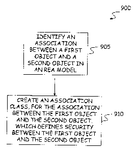
F=G. 9 is a block diagram 900 illustrating a
method of providing Resource-Event-Agent (REA)
model based security. The method illustrated in
CA 02506250 2005-05-25
f .,
-29-
FIG. 9 summarizes the methodology disclosed above,
but does not limit the present invention to this
particular method. As shown at block 905, the
method includes identifying an association between
a first object and a second object in an REA model.
Then, as shown at block 910, an association class
is created for the association between the first
object and the second object. The association
class, for example called a Security Policy
Association Class, defines security between the
first object and the second object.
The association class, defined between the
first object and the second object, is an object
having properties. The properties of the
association class object define the security
between the first object and the second object. The
step of creating the association class can further
comprise creating one or more association class
objects having properties, with the properties of
the one or more association class objects defining
security between a first class of objects of which
the first object is a member and a second class of
objects of which the second object is a member. The
ascend object is a securable object, such as a
contract or agreement type object, a commitment
type object, an event type object, oz a resource
type object. The first object is of a particular
agent type. A role for a user is defined by the
particular agent type fox the first object.
The association class created between the
first object and the second object can be created
in a security model either separate from the REA
CA 02506250 2005-05-25
.. 4
-30-
model, or as part of the REA model. .The security
defined between the first object and the second
object includes defining permissions and rights of
the first object relative to the second object.
These permissions and rights can be determined
dynamically in a security policy logic module
outside of the security model. This is particularly
useful for permissions and rights which. are
transient in nature, for example depending upon the
l0 date, time, status of an event, etc.
Although the present invention has been
described with reference to particular embodiments,
workers skilled in the art will recognize that
changes may be made in form and detail without
departing from the spirit and scope of the
invention.