Note: Descriptions are shown in the official language in which they were submitted.
CA 02506600 2005-05-17
WO 2004/051767 PCT/SE2003/001721
1
A bipolar battery and a method for manufacturing a bipolar
battery
Technical field
The present invention relates to a bipolar battery, especially
a NiMH battery, as defined in the preamble of claim 1. The
invention also relates to a method for manufacturing a bipolar
battery as defined in the preamble of claim 12.
Background to the invention
Traditionally, bipolar batteries including several cells have
been designed to have separately sealed cells to contain both
electrolyte and gas created during operation. A problem that
has occurred is the creation of an electrolyte path between
adjacent cells due to inadequate sealing properties, which in
turn mainly depend on a pressure difference between adjacent
cells. The pressure difference arises when a cell starts to
gas before the cell next to it starts gassing'. This is a
normal behaviour of cells in a bipolar battery.
A solution to this problem has been suggested in US 5,344,723
by Bronoel et al., which discloses a bipolar battery having a
common gas chamber, which is created by providing an opening
through the biplate (conductive support/separator). The
opening is also provided with a hydrophobic barrier to prevent
passage of electrolyte through the hole. Although the problem
with pressure differences between the cells is solved, there
is still a disadvantage with the described battery. The outer
sealing around the edge of each biplate still has to be fluid-
tight, which is very difficult to achieve. If the outer
sealing is not fluid-tight, the electrolyte, contained in the
separator between the electrodes, may form an electrolyte path
from one cell to another.
CA 02506600 2005-05-17
WO 2004/051767 PCT/SE2003/001721
2
Furthermore, the suggested solution is rather expensive to
implement since an opening has to be made through the biplate
to create the common pressure chamber. If the biplate is
relatively thin, it is even harder to create an opening
through the biplate because tears, stretching, or metal
slivers may form.
There is a need for a battery that is easy to manufacture at
affordable prices, and that are safe to handle during charge
and discharge procedures.
Summary of the invention
The object of the present invention is to provide a bipolar
battery, preferably a bipolar NiMH battery that has a
simplified construction compared to prior art bipolar
batteries.
This object is achieved by a bipolar battery as defined in the
characterising portion of claim 1 and a method for
manufacturing a bipolar battery as defined by the
characterising portion of claim 12.
An advantage with the present invention is that the bipolar
battery is easier to manufacture compared to prior art bipolar
batteries.
Another advantage is that the cost for manufacturing the
bipolar battery is greatly reduced, while maintaining or even
improving the operating properties of the bipolar battery.
Further objects and advantages of the present invention will
be apparent to those skilled in the art from the following
detailed description of the disclosed bipolar electrochemical
battery and the biplate assembly.
CA 02506600 2005-05-17
WO 2004/051767 PCT/SE2003/001721
3
Brief description of the drawings
The different embodiments shown in the appended drawings are
not to scale or proportion, but exaggerated to point out
different important features for the sake of clarity.
Fig. 1 shows a planar view of a first embodiment of a biplate
assembly according to the invention.
Fig. 2 shows a cross-sectional view along A-A in figure 1.
Fig. 3 shows a cross-sectional view of a second embodiment of
a biplate assembly according to the invention.
Fi.g. 4 shows a cross-sectional view of a first embodiment of a
bipolar battery according to the present invention.
Fig. 5 shows a cross-sectional view of a second embodiment of
a bipolar battery according to the present invention.
Fig. 6 shows a planar view of a third embodiment of a biplate
assembly according to the invention.
Fig. 7 shows a cross-sectional view along A-A in figure 6.
Fig. 8 shows a cross-sectional view of a third embodiment of a
bipolar battery according to the present invention.
Fig. 9 shows a first embodiment of a combined frame and
hydrophobic barrier according to the invention.
Fig. 10 shows a second embodiment of a combined frame and
hydrophobic barrier according to the invention.
Fig. 11 shows a third embodiment of a combined frame and
hydrophobic barrier according to the invention.
CA 02506600 2005-05-17
WO 2004/051767 PCT/SE2003/001721
4
Detailed description of preferred embodiments
The major benefits of the bipolar battery design are
simplicity and low resistance losses. The parts count of the
battery is relative low, consisting only of end plates and
biplates, with appropriate assembly and sealing components.
Batteries of a desired voltage are constructed by stacking the
required number of biplates. The electrical connections
between the cells are made as the battery is stacked, since
each biplate is electrically conductive and impervious to
electrolyte.
With the terminals at each end, the flow of current is
perpendicular to the plate, which ensures uniform current and
voltage distribution. Since the current path is very short the
voltage drop is significantly reduced.
Bipolar batteries will also have significantly reduced weight,
volume and manufacturing costs due to elimination of
components and the manufacturing approach.
The major problem with bipolar batteries that has not been
commercially solved before is obtaining a reliable seal
between cells within the bipolar battery.
The seal on a cell is of extreme importance for all types of
batteries, and bipolar batteries are no exception. Individual
cells contain the active materials (for NiMH batteries it is
Nickel hydroxide positive and metal hydride hydrogen storage
alloy negative, respectively), separator and electrolyte. The
electrolyte is required for ion transport between the
electrodes. The best designs, optimised for longevity, weight
and volume, require recombination of gasses.
Batteries always produce gasses as they are charged. The
gassing rate increases as the battery nears full charge, and
CA 02506600 2005-05-17
WO 2004/051767 PCT/SE2003/001721
reaches maximum when fully charged. The gasses which are
produced are primarily oxygen and hydrogen.
Batteries considered for power applications have thin
electrodes. Long life with minimum weight and volume are
5 required attributes, which requires a sealed construction.
Oxygen will recombine rather rapidly, so batteries are
designed so oxygen will be the first gas generated if the cell
is overcharged or overdischarged. This requires two actions:
1) Overbuild the negative active material, generally by 30%,
to ensure that the positive electrode, which will gas oxygen,
will be the first to gas.
2) Provide for gas passage from the positive to the
negative, where the oxygen will recombine. The gas passages
are obtained by controlling the amount of electrolyte within
the pores of the electrode and through the separator. All
surfaces of the electrode must be covered by a thin layer of
electrolyte for the transport of ions, but the layer must be
thin enough to permit gas diffusion through the layer, and
must allow gas passages throughout the active layers and the
separator.
The negative electrode would gas hydrogen if overcharged.
Because hydrogen does not recombine quickly, pressure would
build up within the cell. The oxygen recombination effectively
discharges the negative at the same rate it is being charged,
thus preventing overcharge of the negative.
The surface area of the active material, combined with the
uniform voltage distribution of the bipolar design, enhances
rapid recombination.
CA 02506600 2005-05-17
WO 2004/051767 PCT/SE2003/001721
6
The bipolar approach will ensure that the voltage drop across
the active material will be uniform in all areas, so that the
entire electrode will come up to full charge at the same time.
This will eliminate the major problem in conventional
constructions, where parts of an electrode are overcharging
and gassing while other (remote) areas of the electrode are
not yet fully charged.
The cells in regular batteries are sealed to contain the
electrolyte both for proper performance of the cells, and to
prevent electrolyte paths between adjacent cells. The presence
of electrolyte paths between cells will allow the electrolyte-
connected cells to discharge at a rate that is determined by
the resistivity of the path (length of path and cross section
of path). The seals on bipolar batteries are more important
because the electrolyte path is potentially much shorter. It
should be noted that an important feature of this disclosure
is the use of a horizontal electrolyte barrier to
significantly increase the length of the potential path. An
additional concern is the amount of heat generated by
operation of the cell. Depending on the magnitude of heat
generated, the design must be able to reject the heat and
maintain a safe operating temperature.
If an electrolyte path is developed between cells, a small
intercellular leakage can be overcome by the periodic full
charging of the battery. The battery may be overcharged by a
set amount and at a low rate. The low rate would allow fully
charged cells to recombine gasses without generating pressure
and dissipate the heat from the recombination/overcharge.
Cells that have small intercellular electrical leakage paths
would become balanced.
CA 02506600 2005-05-17
WO 2004/051767 PCT/SE2003/001721
7
The flow of heat in a bipolar cell will occur in a radial
direction, and in fact end plates are preferably somewhat
insulated, to ensure that they operate at the same temperature
as the rest of the battery.
It is rarely necessary that a battery be fully charged to
achieve its useful function. Batteries are routinely over
specified and overbuilt. If an operation requires 50 AH
(Ampere Hours), the requirement is usually specified at least
10% higher. Since batteries lose capacity over their lifetime,
the capacity of a new battery is increased by the expected
loss, resulting in possibly a 70 AH requirement for a new
battery in this example. The manufacturer will probably have a
median design target of 75 AH to allow for variations in the
manufacturing process. Much of this overbuild is to compensate
for the life capacity degradation that is caused by the
overcharging.
Figure 1 is a planar view and figure 2 is a cross sectional
view (along A-A in figure 1) of a first embodiment of a
biplate assembly 10 comprising a biplate 11, preferably made
from Nickel or Nickel plated steel. A negative electrode 12
and a positive electrode 13 are attached to opposite sides,
respectively, of the biplate 11. Each electrode is, in this
embodiment, arranged to cover only a central portion of the
side of the biplate 11 to leave space between each electrode
and the edge 15 of the biplate 11 for implementing a means for
creating a common gas space for all cells in the battery as
described in connection with figure 4 and 5. A hydrophobic
electrolyte barrier 14, preventing electrolyte leakage, is
provided on one side of the biplate 11 around the electrode,
preferably the negative electrode 12, as illustrated in the
embodiment.
CA 02506600 2005-05-17
WO 2004/051767 PCT/SE2003/001721
8
The essential part of the invention is that the electrolyte
leakage around the perimeter of the electrodes is controlled
by the hydrophobic barrier. It is not even necessary that the
electrode covers a central portion of the biplate as long as
there is sufficient space to implement the hydrophobic barrier
and a frame that defines the width of each individual cell, as
is discussed below.
The electrodes 12, 13 may be attached to the biplate 11 in
many ways, but preferably the electrodes are manufactured
directly onto the biplate by using pressed powder, as is
disclosed in the published PCT application PCT/SE02/01359,
with the title "A method for manufacturing a biplate assembly,
a biplate assembly and a bipolar battery" by the same
applicant. By using the method of pressing powder directly
onto the biplate, thin electrodes having less active material
may be manufactured.
The shape of the biplate is preferably rectangular to maximise
the useful area of the biplate and to better use the biplate
for heat conductive purposes. The maximum heat path will be
limited to half the length of the shortest side of the
rectangle.
The electrolyte barrier 14 is made from a suitable hydrophobic
material, such as a flouropolymer or similar materials. The
hydrophobic material may be applied to the biplate as a liquid
or solid material and then cured in place, which will bond the
barrier to the biplate in an efficient way to prevent
electrolyte leakage between cells.
Figure 3 shows a cross sectional partial view of a second
embodiment of a biplate assembly 17 comprising a biplate 11, a
negative electrode 12, a positive electrode 13 and a hydro-
phobic barrier 14 as described in connection with figures 1
CA 02506600 2005-05-17
WO 2004/051767 PCT/SE2003/001721
9
and 2. The second embodiment 17 also comprises an additional
hydrophobic barrier 16 arranged around the positive electrode
13.
The means for creating a common gas space for all cells in a
bipolar battery comprises a frame having a predetermined
thickness which is the desired width of a cell. The frame is
arranged between adjacent biplates and/or a biplate and an end
plate, as described below. The frame is attached to the side
of each biplate in a non-sealing manner to permit gas
generated within a cell'to escape the cell. In another
embodiment, the frame is made with a thermoplastic elastomer
compound that forms a better seal with the biplate, and one or
more leakage channels can be moulded into the frame to ensure
leakage path. When several biplate assemblies are stacked upon
each other, as described in connection with figures 4, 5 and
8, a common gas space will be created which will eliminate the
pressure difference between the cells in a bipolar battery.
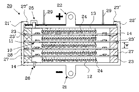
Figure 4 shows a bipolar battery 20 in cross section having
five cells. The battery comprises a negative end terminal 21
and a positive end terminal 22, each having a negative
electrode 12 and a positive electrode 13, respectively. No
hydrophobic barrier needs to be provided around the electrodes
12, 13 arranged to the end terminals 21 and 22. Four biplate
assemblies 10 are stacked on top of each other in a sandwich
structure between the two end terminals 21, 22. A separator 24
is arranged between each adjacent negative 12 and positive 13
electrodes making up a cell, the separator contains an
electrolyte and a predetermined percentage of gas passages,
about 5 % is a typical value for gas passages.
A frame 23 is provided between adjacent biplates 11 and/or a
biplate 11 and an end terminal 21 or 22. As indicated in the
CA 02506600 2005-05-17
WO 2004/051767 PCT/SE2003/001721
figure by the arrow 28, gas may migrate from one cell to
another and thereby all cells share a common gas space through
the gas passages created between the frames 23 and the
biplates 11. If an electrode in a cell starts to gas before
5 the others, this pressure will be distributed through-out the
whole common gas space.
If the pressure within the common space exceeds a predeter-
mined value, a pressure relief valve 25 will open to connect
the common gas space with the ambient environment. The
10 pressure relief valve 25 is arranged through one of the end
terminals, in this example the positive end terminal 22 and
comprises a feed-through.
Additionally, a pressure sensor 26 may also be mounted through
one of the end terminals, in this example the negative end
terminal 21, to measure the actual pressure inside the battery
cells. The negative end terminal 21 is designed as a part of a
metallic casing 27, which is insulated against the biplates 11
and the positive end terminal 22 being a part of the bipolar
battery. Each frame 23 is made from an insulating material and
is designed in such a way to ensure electrical insulation
between each biplate 11 and the metallic casing 27, by
providing a recess 23' where the biplates and the positive end
terminal are placed during manufacture and are maintained
during operation by applying a pressure as indicated by the
arrows 29.
The pressure is maintained by folding down a part of the
metallic casing 27, and will ensure that each cell has a
predetermined width w, which is approximately equal to the
height of the frame 23. To avoid an electrical connection
between the casing 27 and the positive end terminal 22, there
is provided an insulating layer 22' on top of the positive end
CA 02506600 2005-05-17
WO 2004/051767 PCT/SE2003/001721
11
terminal 22. Alternatively, the cover may be fixed in position
by any of several other standard means, including crimping,
welding, interference fits, epoxy, heat seal or solvent,
depending of the battery case construction and battery
application criteria.
Relief valves and pressure sensors are readily available to a
man skilled in the arts and are not described in more detail.
The bipolar battery according to figure 4 is manufactured by
the following steps:
(1) A casing 27 is provided, which will serve as the negative
end terminal 21 together with a negative electrode 12.
(2) A first separator 24 is arranged on top of the negative
electrode 12 and a first frame 23 is arranged around the
electrode 12. Electrolyte is naturally added to the separator.
(3) A first blplate assembly 10, as described zn connection
with figures 1 and 2, is arranged on top of the frame 23 so
that the biplate 11 is positioned in the recess 23'.
(4) A second separator 24, provided with electrolyte, is
arranged on top of the negative electrode 12 of the first
biplate assembly 10, and a second frame 23 is arranged around
the electrode 12.
Step (3) and (4) are repeated until a desired number of cells
have been created.
(5) A positive end terminal 22, including a positive
electrode 13 and an insulating outer layer 22', is thereafter
placed in the recess 23' of the upper frame 23.
(6) A pressure is applied to the stacked components making up
the bipolar battery as indicated by arrows 29.
CA 02506600 2005-05-17
WO 2004/051767 PCT/SE2003/001721
12
(7) The upper edge 27' of the metallic casing 27 is
thereafter folded down to maintain the applied pressure.
The bipolar battery is completed.
Figure 5 shows a second embodiment of a bipolar battery 30
according to the invention, comprising a negative end terminal
31, a positive end terminal 32 and four stacked biplate
assemblies 17. The construction of this battery differs from
the battery described in connection with figure 4 in the
following way.
No recess is present in the frame 33 determining the width w
of each cell. Hydrophobic electrolyte barriers 14 and 16 are
present around both the negative electrode 12 and the positive
electrode 13 that will prevent passages of electrolyte from
one cell to another around the edge of the biplate 11.
Hydrophobic barriers are even present around the negative 12
and positive 13 electrodes of the end terminals, although this
is not necessary to maintain operation of the battery. A
metallic casing 34 is provided having an insulating layer 35
arranged on the inside, and a separate negative end terminal
31 is therefore present.
The main feature of the second embodiment is that it is
possible to further simplify the manufacturing method by
coating the inside of the casing 34 with an insulating layer
35. The frames 33 in this embodiment only have the purpose of
determining the width w of each cell and electrically insulate
the biplates 11 and end terminals 31, 32 from each other. On
the other hand a non-metal casing could be used instead of a
metal casing provided with an insulating layer on the inside.
Any type of suitable containers known to the battery industry,
including moulded plastic containers, could be used as casing
CA 02506600 2005-05-17
WO 2004/051767 PCT/SE2003/001721
13
for the bipolar battery according to the invention, as long as
the battery operates at an appropriate pressure.
It is of course possible to remove the insulating layer from
the bottom of the metal casing 34, and allow the negative end
terminal 31 to be in contact with. the casing 34.
The bipolar battery according to figure 5 is manufactured by
the following steps:
(1) A casing 34 is provided, having an insulated layer 35
arranged on the' inside, or being made from a non-conductive
material, such as moulded plastics.
(2) A negative end terminal 31, including a negative
electrode 12 with a hydrophobic barrier 14 around it, is
arranged within the casing and the terminal is accessible
through an opening in the bottom of the casing 34.
(3) A first separator 24 is arranged on top of the negative
electrode 12 and a first frame 33 is arranged around the
electrode 12. Electrolyte is naturally added to the separator.
(4) A first biplate assembly 17, as described in connection
with figure 3, is arranged on top of the frame 23 so that the
edge of the biplate 11 is close to the insulated layer 35.
(5) A second separator 24, provided with electrolyte, is
arranged on top of the negative electrode 12 of the first
biplate assembly 17, and a second frame 33 is arranged around
the electrode 12.
Step (4) and (5) are repeated until a desired number of cells
have been created.
CA 02506600 2005-05-17
WO 2004/051767 PCT/SE2003/001721
14
(6) A positive end terminal 32, including a positive
electrode 13, and an inner barrier 16, is thereafter placed on
top of the upper frame 33.
(7) A pressure is applied to the stacked components making up
the bipolar battery as indicated by arrows 29.
(8) The upper edge 34' of the metallic casing 34 is
thereafter folded down, as indicated by the arrows 36, or
fixed in position in an applicable way if a non-metal casing
has been used, to maintain the applied pressure.
The bipolar battery is completed.
The frames 33 provided between the biplates 11, and the
biplate 11 and the end terminals 31, 32, will create a common
gas space and, as described in connection with figure 4, the
electrolyte barrier 14 together with. the additional barrier
16, will prevent passages of electrolyte from one cell to
another. Preferably, a pressure relief value (not shown) is
provided together with a pressure sensor (not shown) to
monitor the pressure within the battery. The pressure relief
valve and the pressure sensor may be mounted on any suitable
surface as long as there is a communicating passage to the
commonly connected cells of the battery.
In the case where a non-conductive casing has been used,
terminations may go from the end plates 31, 32 to terminal
penetrations in any fashion known to a person skilled in the
art, and could be routed, either internally or externally, to
be located on any or the same surface as the end plates.
Figure 6 shows a planar view of a third embodiment of a
biplate assembly 40, and figure 7 shows a cross-sectional view
along A-A in figure 6. A negative electrode 12 and a positive
CA 02506600 2005-05-17
WO 2004/051767 PCT/SE2003/001721
electrode 13 are arranged on each respective side of a biplate
11, as previously described in connection with figures 1-3.
A hydrophobic barrier 41 is provided around the edge of the
biplate 11. In this embodiment, a part of the positive and
5 negative side of the biplate 11 is covered with the
hydrophobic barrier, although this is not necessary to obtain
the advantages of the hydrophobic barrier. However, the
biplate will in some applications be very thin and there will
be a problem when attaching the hydrophobic barrier only to
10 the edge of the biplate 11.
Figure 8 shows a third embodiment of a bipolar battery 50
using biplate assemblies 40 as disclosed in figure 6 and 7.
The basic construction of the battery 50 is the same as the
battery described in connection with figure 4 with a few
15 exceptions:
- Frames 51 of a different type have been used, that are
similar to the frames used in the battery described in
figure 5, having an opening 52 to provide a gas passage
between each cell and the space near the casing 27.
- At least one ridge 53 is also provided along the inside
of the casing 27 to define the position of the edge of
the biplate assembly 40. The distance between the casing
and the biplate assembly 40 is defined by the height of
the ridge 53, and the space created will allow gas
passage between the cells.
- The hydrophobia barrier 41 is provided on the outside of
the frames 51 and the ridge 53 define the space that will
allow gas passage on the side of the hydrophobic barrier
41.
CA 02506600 2005-05-17
WO 2004/051767 PCT/SE2003/001721
16
The frames 23, 33 and 51, used in the embodiments above, are
providing a controlled gaseous leakage between adjacent cells,
but the present hydrophobic barrier 14, 16 and 41 will
prohibit the creating of an electrolyte path between adjacent
cells. To further enhance the built-in gaseous leakage between
the cells, a rough surface of the frame may be provided to
ensure a higher degree of non-sealing between the frame and
the biplates 11.
The frame 23, 33 and 51 preferably has good heat conductive
properties, so that heat created within the battery easily can
escape through the casing 27, 34. Preferably, the insulation
35 provided on the inside of the casing 34 in figure 5 also
has good heat conducting properties for the same reason as
discussed above.
The positive active material in a NiMH battery manufactured
according to the invention is preferably made from spherical
nickel hydroxide (supplied by OMG, Finland); Nickel 210 fiber
(supplied by INCO, USA); and Powdered Cobalt (obtainable from
various suppliers). The negative material is preferably made
with Metal Hydride (supplied by Treibacher, Austria); and
Nickel 255 fiber (supplied by INCO, USA). There are numerous
suppliers of all these materials, particularly in Japan and
China, where the majority of Nickel Metal Hydride cells
presently are manufactured.
No other materials, such as conductive additives, binders,
etc. are used in the following illustrative example. The
nickel fibers INCO 210 and 255 serve as the conductive
additives and make contact with the conductive biplate,
conducting current from the active material directly to the
conductive biplate. Any type of electrode construction could
be used either as it is, or with a layer of any conductive
CA 02506600 2005-05-17
WO 2004/051767 PCT/SE2003/001721
17
material that improves contact, to benefit from the
construction according to the invention.
The essential feature of the invention is the built-in leakage
that will provide the possibility to use of the battery
container as the common pressure vessel without having to
provide a liquid and a gas seal in each cell, nor a hole with
a barrier in each biplate. The presence of at least one
hydrophobic barrier between a positive and a negative
electrode arranged adjacent to a biplate will prevent
electrolyte leakage between adjacent cells, as discussed
above.
The concept of the invention will work for a wide variety of
dimensions, such as the physical dimensions of the frame, the
thickness of the electrodes, biplates, and separator. The key
is the distance between the biplates defining a cell. It is
necessary that the gap is sufficient that any capillary
wetting forces between the biplates are less than the
hydrophobic properties of the barriers. The gap is equally
dependent upon the quality of electrolyte available in the
battery. Obviously, a battery that is flooded with electrolyte
will not be prevented from forming an electrolyte bridge
regardless of the hydrophobic properties and dimensions of the
barriers. A complete seal is required for flooded batteries.
In the design of starved electrolyte batteries, which is
applicable to the present invention, is how all sealed Nickel
Metal Hydride batteries are designed. The quantity of
electrolyte plays an important factor in the life of the
battery. The electrodes and the separator compete for the
available electrolyte, along with the wetting of the biplate
surface. The lower amount of electrolyte, the smaller the
CA 02506600 2005-05-17
WO 2004/051767 PCT/SE2003/001721
18
barrier requirement, but also the lower the life of the
battery.
Design features such as the compression of the separator
impacts the capillary forces within the separator. The choice
of separator could be relevant due to their ability to retain
and absorb electrolyte. Cylindrical cells require strong
separator to withstand the automated winding assembly process.
As a consequence, they use larger diameter fibres to achieve
the strength. Separators made with these fibres have lower
electrolyte retention and absorption properties, and lose
electrolyte to the electrodes as the electrodes dry or absorb
electrolyte within the electrode. The use of finer fibres,
with a higher absorption and electrolyte retention properties
are desirable in batteries, and are the preferred material for
use in the bipolar battery with built-in leakage. The
separator fibers should have a diameter in the range of 0.0001
to 0.015 inches (approx. 2.5 to 400 ~tm), preferably in the
range of 0.003 to 0.008 inches (approx. 76 to 200 ~.m).
The frame material may be any suitable material that is non-
conductive and that is compatible with the electrochemical
environment inside the battery cells. The preferred approach
is to mould the frames, and any injection mouldable material
from the generic families of ABS or polypropylene is
acceptable. A mouldable thermoplastic elastomer compound could
also be used as frame material. An example of a material for
use in moulding the frames is Kraton G 7705 or equivalent.
When this material is compressed it forms an adequate seal to
prevent electrolyte paths, and it is also possible to mould
passages in the material to ensure gas flow leakage paths as
desired, see figures 9-11.
CA 02506600 2005-05-17
WO 2004/051767 PCT/SE2003/001721
19
The invention relies on the feature of allowing gas passage,
but preventing passage of electrolyte, between cells. The
required dimension of the gas passage must be adequate for the
passage of all gasses generated on overcharge, and a lower
limit for cells up to 10 AH (Ampere Hours) is an opening with
a cross section of 0.003 square inches (approx. 1.94 mm~). The
cross section of the opening is proportionally larger, or more
openings are provided, as the battery capacity for each cell
increases.
The width of the hydrophobic barrier, which prevents
electrolyte migration between adjacent cells, is preferably in
the range 0.020 to 0.125 inches (approx. 0.5 to 3 mm), and
more preferably in the range of 0.050 to 0.060 inches (approx.
1.3 to 1.5 mm. The thickness of the hydrophobic barrier
depends on the material and means of application. As thin as
possible is preferred.
An illustrative example of a biplate assembly and a bipolar
NiMH battery will be described in more detail below as a non-
limited example to further illustrate the benefits from the
inventive design.
In an example of a 10 AH cell in a NiMH battery, the height of
the frame depends on the application and thus the thickness of
the electrodes. The thickness of the electrodes is in the
range of 0.002 to 0.050 inches (approx. 0.05 to 1.3 mm), with
a preferred range of 0.010 to 0.035 inches (approx. 0.25 to
0.90 mm). The electrodes normally have the shape of a
rectangle with a width of not more than 6 inches (approx. 150
mm) due to temperature requirements and a hydrophobic barrier
arranged around each electrode. The thickness of the biplate
is in the range of 0.001 to 0.005 inches (approx. 25 to 125
CA 02506600 2005-05-17
WO 2004/051767 PCT/SE2003/001721
~,m), preferably in the range of 0.0025 to 0.003 inches
(approx. 64 to 76 ~.m) .
Figures 9-11 show three different embodiments for a combined
frame and hydrophobic barrier.
5 The first embodiment of a frame 60 made from a hydrophobic
material is shown in figure 9. The frame is moulded to the
biplate 11 and a moulded channel 61, extending to the outside
of the frame, is provided in the frame 60.
The second embodiment, shown in figure 10, comprises a frame
10 70 made from a hydrophobic material. The frame is moulded to
the biplate 11, as the frame 60 discussed in connection with
figure 9, and a moulded channel 71, extends from the inside of
the battery cell to a moulded hole 72 within the frame 70.
The third embodiment, shown in figure 11, also comprises a
15 frame 80 made from a hydrophobic material. The frame is
separately moulded, provided with a recess 81 for holding the
biplate 11 and provided with a moulded channel 82, extending
to the outside of the frame 80.
When the hydrophobic frame 60-80, as disclosed in connection
20 with figures 9 to 11, is put under pressure, during the last
stage of the assembly process, it will provide an adequate
seal against the biplate 11 to prevent any electrolyte paths
to be formed between adjacent cells. Thus eliminating the need
for a separately arranged hydrophobic barrier, as illustrated
in figures 1 to 8.
The means used to provide the pressure inside the finally
assembled battery could also include the use of tie rods
between the end plates. The tie rods could even be applied in
a central part of the end plates, which indicate that they
CA 02506600 2005-05-17
WO 2004/051767 PCT/SE2003/001721
21
pass through the electrode area. If one or more holes within
the electrode area are necessary, a hydrophobic barrier is
needed around each hole to prevent electrolyte leakage between
adjacent cells and equivalent clearance of the tie rods from
the electrodes to the separator, from the separator to the
hydrophobic barrier, and the designed hole.