Note: Descriptions are shown in the official language in which they were submitted.
CA 02506711 1999-08-21
WO 00/11398 PCT/IJS99/1914'J
FIBER OPTIC LUMINAIRE
Background of the Invention
1. Field of the Invention
The present invention relates generally to luminaires, and more particularly,
to
a fiber optic luminaire adaptable to many different configurations and having
a
controlled light distribution.
2. Description of the Rested Art
Light conducting, light shaping and light distribution structures are known.
For example, it is known to couple light energy along a fiber optic cable from
a light
source to a luminaire. The light source provides a source of light energy, and
the
luminaire is constructed to distribute the light energy with a desired
intensity and in a
desired pattern The fiber optic cable provides a conduit for transporting the
light
energy fiom the light source to the luminaire. It is also known to provide
light
distributing fiber optic cable. Such fiber optic cable is adapted to scatter
light energy
outwardly from its surface as the light energy is coupled along the length of
the fiber.
Because these fibers scatter the light energy there is little or no control of
the light
energy distribution. Hence, the intensity of the light distribution varies
substantially
along the length of the fiber.
Light pipes too are devices that find application in light distribution
applications. A light pipe is typically arranged to couple light energy from
alight
source along its structure. Additionally, the light pipe is arranged to
distribute the
light energy finm its structure in a desired pattern. In this manner the light
pipe acts
both as the conduit and as the luminaire. Light pipes are typically adapted
for a
particular light distribution application. For example, a light pipe is shown
in United
States Patent No. 5,050,946 for providing backlighting to a liquid crystal
display
(LCD). Similar arrangements are shown in United States Patent Nos. 5,295,048;
5,394,255; 5,390,276; 5,594,830; 5,600,455 and 5,600,462. Another example of a
light pipe application is instrument cluster lighting in an automobile.
In the light pipe arrangement shown in United States Patent No. 5,050,946 a
planar faceted back surface is used to reflect light energy, substantially
uniformly,
through a planar top surface. The other of the above-referenced patents show
similar
arrangements for coupling and distributing light energy from a light source
into a
CA 02506711 1999-08-21
WO 00/11398 PGT/US99/19147
-2-
planar pattern for providing LCD backlighting. Still, all of these
arrangements have
generally been limited to planar light distribution applications.
What is needed then is a luminaire device offering greater flexibility in its
construction and configuration while providing precise light distribution.
Summa,~y o~the Invention
In a preferred embodiment of the present invention, a fiber optic luminaire
includes an optic fiber having an outer surface, a length and a light entrance
surface.
A light source provides a source of light energy and is disposed adjacent the
entrance
surface. Light rays from the light source are coupled into the optic fiber at
the
entrance surface. The optic fiber conducts the light rays along its length and
within
the outer surface. The outer surface is formed with a plurality of non-
scattering light
redirecting structures. The light redirecting structures have a distribution
density that
varies as a function of the length. Each light redirecting structure is
arranged to
redirect a light ray incident to it through the outer surface.
In another preferred embodiment of the present invention, a light distribution
device includes an optic fiber core. The optic fiber core has an outer
surface, a length
and an entrance surface. The entrance surface is arranged for coupling light
rays from
a light source into said optic fiber. The optic fiber is arranged for
conducting the light
rays along its length and within the outer surface. The outer surface is
formed with a
plurality of light redirecting structures, and each light redirecting
structure is arranged
to redirect a light ray incident to it through the outer surface. An optical
capillary
surrounds the optic fiber core. The optical capillary is arranged for
scattering the light
rays distributed from the fiber optic core.
In yet another preferred embodiment of the present invention a fiber optic
luminaire includes an optic fiber core. The optic fiber core has an outer
surface, a
length and an entrance surface, and the entrance surface is arranged for
coupling light
rays from a Iight source into the optic fiber core. The optic fiber core is
arranged to
conduct the light rays along its length and within said outer surface. An
optical
capillary surrounds the optic fiber core. The optical capillary has an inner
capillary
surface and an outer capillary surface. The inner capillary surface forms an
annular
chamber between the fiber optic core and the optical capillary. The inner
capillary
surface is also formed with a plurality of light redirecting structures. Each
light
CA 02506711 1999-08-21
WO 00/11398
PCTNS99/1914~
-3-
redirecting structure is arranged to cause a leakage of light rays from the
optic fiber
core adjacent the light redirecting structure, and the optical capillary is
arranged for
scattering the leaked light rays.
In still another preferred embodiment of the present invention, an illuminated
apparatus includes an apparatus housing arranged to receive a fiber optic
luminaire.
The fiber optic luminaire includes an optic fiber. The optic fiber has an
outer
surface, a length and an entrance surface. The entrance surface is arranged
for
coupling light rays from a light source into said optic fiber, and the optic
fiber is
arranged for conducting said light rays along said length and within said
outer surface.
The outer surface is also formed with a plurality of light redirecting
structures. Each
light redirecting structure is arranged to redirect a light ray incident to it
through said
outer surface.
Preferred exemplary embodiments of the invention ate illustrated in the
accompanying drawings in which like reference numerals represent like parts
throughout, and in which:
Figure 1 is a front perspective view of a fiber optic luminaire;
Figure 2 is a longitudinal cross-section view taken along a portion of the
fiber
optic luminaire shown in Figure 1 as indicated by line 2 - 2 of Figure 1;
Figure 3 is a schematic illustration of a portion of the fiber optic luminaire
shown in Figure 1 illustrating light intensity changes associated with the
light
redirecting structures;
Figure 4 is a front perspective view of a fiber optic luminaire formed in a
torpid shape;
Figure 5 is a front perspective view of a fiber optic luminaire in accordance
with an alteniate preferred embodiment of the present invention;
Figure 6 is cross-section view of the fiber.optic luminaire of Figure 5 taken
along line 6-6 of Figure 5;
Figure 7 is a cross-section view of an alternative arrangement of the fiber
optic
luminaire illustrated in Figure 6;
Figure 8 is a longitudinal cross-section vie~r of a fiber optic luminaire in
accordance with an alternate preferred embodiment of the present invention;
CA 02506711 1999-08-21
WO 00/11398 PCT/US99/19147
-4-
Figure 9 is a front perspective view of a fiber optic luminaire in accordance
with an additional alternate preferred embodiment of the present invention;
Figure 10 is a front perspective view of a fiber optic luminaire in accordance
with an alternate preferred embodiment of the present invention;
Figure 11 is a front view of a lock-cylinder arranged with a fiber optic
luntinaire;
Figure 12 is a cross-section view of the lock-cylinder shown in Figure 11
taken along line 12-12 of Figure 11; and
Figure 13 is a front view of an illuminated sign arranged with several fiber
IO optic luminaires.
Detailed Description of the Preferred Embodiments
1. Resume
A fiber optic luminaire is arranged to couple light energy from a light source
along its length. The fiber optic luminaire is also arranged with a plurality
of light
redirecting structures distributed along its length; the light redirecting
structures are
arranged to uniformly distribute light from the fiber optic luminaire. The
light
redirecting structures are preferably non-scattering structures, including
structures
such as microprisms, microfacets, microgrooves and micrometers. The fiber
optic
luminaire may be amangod in a variety of shapes. The fiber optic luminaire may
also
include an optical capillary disposed about its surface and along its length.
The fiber
optic luminaire and the capillary may be arranged with light reflecting and
collimating
structures for providing unique light distribution patterns.
2. Fiber Optic Laminaice
Referring then to the drawings and particularly to Figure 1 of the drawings, a
fiber optic luminaire 10 in accordance with a preferred embodiment of the
present
invention includes-an optic fiber 12 formed with a plurality of light
redirecting
structures 14 distributed along its length, L. Optic fiber 12 includes an
outer surface
16 and an entrance surface 18. Entrance surface 18 is disposed adjacent a
light source
20. Light source 20 provides a source of light energy, which light energy is
coupled
into optic fiber 12 at entrance surface 18 and is conducted along the length
of optic
fiber 12 in accordance with total internal reflection (TIR). It will be
appreciated that a
CA 02506711 1999-08-21
WO 00/11398 PGT/US99l19t47
-5-
light energy coupler (not shown) may be used to efficiently couple light
energy from
light source into fiber optic luminaire 10.
Each light redirecting structure 14 is arranged to redirect a portion of the
light
energy conducted along optic fiber 12 and incident to redirecting structure 14
through
outer surface 16. With continued reference to Figure 1 and also referring to
Figure 2,
in a preferred embodiment, light redirecting structures 14 are formed into
outer
surface 16. It is important to note that while shown in Figure 2 as being
located in a
bottom portion of optic fiber 12, light redirecting structures 14 may be
formed all
around surface 16. Light redirecting structures 14 may be continuous
circumferentially about surface 16, but may also be discontinuous as
illustrated by the
broken lines in Figure 1. As will be described more fully below, light
redirecting
structures 14 are further preferably distributed relative to the length L of
optic fiber 12
such that a uniform distribution of light rays 22 from fiber optic luminaire
10 is
achieved. That is, light energy radiated from fiber optic luminaire 10 is
uniform over
its length.
Light redirecting structures 14 are preferably microprism, microfacet,
microgroove, or micrometer structures formed in outer surface 16, and light
redirecting structures 14 are shown as microfacets in Figure 2. In this
regard, light
redirecting structures 14 are non-scattering structures. Thus, a light ray 24,
incident to
a light redirecting structure 14 is reflected, e.g., light ray 23, without
scattering, at an
angle such that it is no longer internally reflected, and exits through outer
surface 16
as light ray 22. Additional light rays, such as light ray 26, not incident to
a light
redirecting structure 14 is conununicated along optic fiber 12 in accordance
with TIR.
A particular advantage of the present invention over light scattering optical
fibers is that the light redistributing structures 14 may be distributed along
the length
L of optic fiber 12 to provide a uniform light distribution over the entire
length of
fiber optic luminaire 10, or to provide a customized light distribution having
different
distribution intensity at various locations along fiber optic luminaire 10.
Light
scattering optical fiber does not provide such control, and thus, does not
provide a
tunable light distribution With continued reference to Figure 2, light
redirecting
structures 14 are separated longitudinally by a separation AZ along optic
fiber 12. In
accordance with a preferred embodiment of the present invention, for uniform
light
CA 02506711 1999-08-21
WO 00111398 PC1'/US99/19147
-6-
distribution over the entire length of fiber optic luminaire 10, DZ varies as
a function
of position along optic fiber 12 having a total length L. Once again it should
be noted
that light redirecting structures do not need to be continuous about outer
surface 16 at
a location z, and this is illustrated by the broken lines in Figure 1.
Incident light, lo,
enters optic fiber 12 through entrance surface 18, and I is the intensity of
the light
energy after passing through a scalar distance 1, and dl represents an
infinitesimally
small portion of the scalar distance 1. Figure 3, illustrates dl, and dl, the
portion of
light energy "leaked" or illuminated from optic fiber 12 as a result of light
rays
interacting with light redirecting structures 14. In the illustrated geometry,
l is the
intensity of the light energy entering at the left of optic fiber 12 reduced
by dl over a
length dl, which holds true for any coordinate z. A general equation (1) may
be
formed indicating that the leakage of light -dl must be proportional to I.
_ dl _- alalz (1)
The leakage of light dlis also proportional to the length dl as well as the
density p of
light redirecting structures 14. The proportionality constant a is interpreted
below.
The density p is the number of light redirecting structures dN per unit
incremental
distance dl and is given by equation 2.
p =_ d (2)
So the units for p arc struchues/can. The light energy intensity 1 is oqual to
to for I =
0, and N, is the total number of light redirxting structures. In order to
pr~escrve
uniform light distribution, dl must be proportional only to dz. As the light
energy
intensity 1 necessarily decreases as one moves along optic fiber 12, z must
correspondingly increase. In equation (3) a constant A is substituted for the
value I,
for the uniform distribution condition.
dl = -aAdz (3)
Since a and A are both constant, integration of equation (3) yields equation
(4).
I = to - aAdz (4)
Equation (5) represents that the density of grooves is equal to a constant
divided by
equation (4), following directly then:
p= j=I
0
CA 02506711 1999-08-21
WO 00/11398 pC1'NS99/19147
_ '7 _
Therefore, p is a function of z and increases monotonically from an initial
density Po.
As mentioned, both A and a are constants, and
- d/ = a/ dN dz = aldN (6)
Integrating equation (6) yields equation (7).
I = I°e-°N (7)
Equation (8) defines a.
- dl
a dN (8)
The value dill represents a relative leakage per infinitesimal length dl, and
dN is the
number of grooves per infinitesimal length dl. Thus, a is a percent
distribution of
light energy per light redirecting structure. If the light energy intensity I
at length z =
L, the full length of optic fiber 12, is desired to be 0, i.e., at the end of
optic fiber 12
all light energy has been reflected through surface 16, then
aA =- L (9)
Equation (9) represents a singularity because the density at the full length L
cannot
reach infinity. For practical purposes, it can be assumed that no more than S
% of the
light energy is linked all the way to the end of optic fiber 12. For the case
where 5
of the light energy remains at the end of optic fiber 12, then aN=3 as given
by
Equation (7).
aN = 3 ~ I = I°e-' . O.OSIo (10)
As noted, a higher density would result in less light energy left ax the end
of optic
fiber 12, but this situation may be limited by the physical possibility of
compacting
the light redirecting structures 14. Moreover, a mirror may be placed at the
end to
reflect the light energy remaining at the end back toward the source.
The total number N, of light redirecting structures 14 may be represented by
Equation ( 11 ) in which the length L of optic fiber 12 is divided by AZ, the
average
distance between light redirecting structures 14.
N, _ ~ (11)
CA 02506711 1999-08-21
WO 00/11398 PGTNS99/! 9147
_g_
In the following example, the average length AZ between light redirecting
structures 14 is given as 100 microns over a total optic fiber length of 20 cm
yielding
a total number of light redirecting structures of approximately 2000 - as
shown in
Equation ( 12).
_ 20cm _ 200mm _
N' - 100 fon ! O.lmm - 2000 ( 12)
With Nr known, and with aN,=3, a may be calculated as is accomplished in
Equation
(13).
a=2~=15(10-')=0.0015 (13)
The average percentage of the total light energy reflected by each light
redirecting
structure is thus 1.5 x 10⁻³ for the given example.
Light redirecting structures 14 have been described in terms of singular
entities. It will be appreciated that light redirecting structures 14 may also
represent
clusters of microprisms, microfacets, microgrooves, micrometers, and various
combinations thereof. In this regard, a is constant for each cluster, aZ is
the average
spacing per cluster and N, is the total number of clusters.
What should be most appreciated by the foregoing discussion is that the fiber
optic Iuminaire has a very tunable light distribution. By controlling the
total number,
density, average leakage and distribution of the light redirecting structures
14, the
amount of light distribution per unit length of optic fiber 12 may be
controlled, and
more preferably, tuned and optimized for a particular application.
Fiber optic luminaire 10 may be formed from standard fiber optic cable. A
first step is to remove the cladding from the fiber optic cable to expose
outer surface
16. Next, redirecting structures 14 are formed into outer surface 16 using a
suitable
micro-forming technology such as embossing or molding. Next, an end surface is
prepared to form entrance surface 18. Entrance surface 18 is then arranged
adjacent a
light source 20 or another source of light energy.
Referring now to Figure 4, a fiber optic luminaire 110 includes an optic fiber
112 formed in a toroid shape and including a plurality of light redirecting
structures
114 (shown in broken lines) distributed about its circumference. Optic fiber
112
includes an outer surface 116 and a first entrance surface 118 and a second
entrance
CA 02506711 1999-08-21
WO 00/11398 PGTlUS99/19147
-9-
surface 119. A light source 120 is dispose between entrance surface 118 and
entrance surface 119. Light source 120 provides a source of light energy,
which light
energy is coupled into optic fiber 112 at each of entrance surface 118 and
entrance
surface 119 and is conducted along the circumference of optic fiber 112 in
accordance
with total internal reflection (TIR). In this regard, optic fiber 112 is
formed into a
toroid having a radius R, and optic fiber 112 itself has a core radius r.
Optic fiber 112
is preferably a multimode conductor with core radius r in the range of 100
micrometers (pro) to 1 millimeter (mm). To preserve TIIt, the ratio R/r is
maintained
much greater than 1. It will be appreciated that a light energy coupler (not
shown)
may be used to efficiently couple light energy from light source 120 into
fiber optic
luminaire 110. Also, only one of entrance surface 118 and entrance surface 119
may
be illuminated by light source 120 without departing from the scope of the
present
invention.
Each light redirecting structure 114 is arranged to redirect a portion of the
light energy conducted along optic fiber 112 and incident to a light
redirecting
structure 114 through outer surface 116 in the manner described above with
respect to
fiber optic luminaire 10. For example, light redirecting structures 114 may
have a
density distribution in accordance with Equations (1) - (13) so as to obtain a
uniform
distribution of light rays 122 from fiber optic luminaire 110.
3. Fiber Optic Lumfnalre with Optical Capillary
Referring now to Figure S, a fiber optic luminaire 210 includes an optic fiber
core 212 surrounded by an optical capillary 224. Optic fiber core 212 is
formed with
a plurality of light redirecting structures 214 in an outer surface 216. Optic
fiber core
212 further includes an entrance surface 218 disposed adjacent a source of
light
energy (not shown) for coupling light energy into optic fiber core 212. Light
energy
is conducted along fiber optic core 212 and within outer surface 216 in
accordance
with the TIR. A light ray, such as a light ray 226, incident to a light
redirecting
structure 214, however, is reflected such that it exits outer surface 216 and
is
conducted through optical capillary 224 as light ray 222.
Referring now to Figure 6, optical capillary 224 is formed from an optically
transparent material, and further may be formed from an optically transparent
material
having scattering or diffusing properties. For example, optical capillary 224
is shown
CA 02506711 1999-08-21
WO 00/11398 PCT/~1599/19147
- 10-
to scatter light rays 222 as they exit a capillary outer surface 230. To
prevent
unwanted coupling of light energy between optic fiber core 212 and optical
capillary
224, a small gap 236, on the order of a micron, is provided between an inner
capillary
surface 232 of optical capillary 224 and outer surface 216 of optic fiber core
212.
Optical capillary 224 may further include a reflecting surface 228 formed
along a bottom portion 240 of capillary outer surface 230 as shown in Figure
6. In
this regard, reflecting surface 228 may be formed as a reflective material
deposited on
outer surface 230 and/or outer surface 230 may be formed with light
redirecting
structures, such as mieroprisms, microfacets, microgrooves and micrometers.
Reflecting surface 228 causes light rays 238 to be reflected at a bottom
portion 240 of
optical capillary 224 and exit at an upper portion 242 of optical capillary
224. In this
manner, the light distribution firm fiber optic luminaire 110 may be further
controlled.
With reference to Figure 7, in an alternative configuration a fiber optic
luminaire 310 includes an optic fiber core 312 and an optical capillary 324.
Optic
fiber core 312 and optical capillary 324 are respectively configured as
discussed with
respect to optic fiber core 212 and optical capillary 224 of fiber optic
luminaire 210.
In addition, optic fiber core 312 includes a reflecting surface 342 formed on
an upper
portion 344 thereof. Reflecting surface 342 may be a reflecting material
deposited on
a portion of an outer surface 316 of fiber optic core 312 or may be light
redirecting
structures formed in outer surface 316 and arranged to direct light rays
downward, as
shown in Figure 7, from optic fiber core 312. In addition, optical capillary
324
includes a reflecting surface 328 formed at a bottom portion 340 thereof.
Preferably,
reflecting surface 328 is arranged as a collimating reflecting surface for
collimating
light rays incident thereon. Likewise, optical capillary 324 is formed from a
non-
scattering optically transparent material. In this regard, fiber optic
luminaire 310
provides a source of collimated light rays 322.
Referring now to Figure 8, an alternative preferred embodiment fiber optic
luminaire 410 includes an optic fiber core 412 and an optical capillary 424.
Optic
fiber core is not formed v~iith light redirecting structures. Instead, optical
capillary
424 is formed with a light redirecting structure 450 including a projection
452 and a
corresponding indentation 454 formed in an inner capillary surface 432 (not
shown).
CA 02506711 2006-02-07
-11-
Projection 452 and indentation 454 causes a local distortion 456 in optic
fiber 412.
Local distortion 456 causes localized leakage of light rays 458 from optic
fiber 412.
Light rays 458 are conducted through an optically transparent upper portion
460 of
optical capillary 424. A bottom portion 440 is formed as a reflecting surface
428
similar in arrangement to reflecting surfaces 228 or 328 discussed above. In
this
manner, standard fiber optic cable may be used to form optic fiber 412 without
further
modification.
One of ordinary skill in the art will immediately appreciate from the
foregoing
discussion that the present invention offers tremendous flexibility. For
example, very
l0 precise and uniform light distribution may be obtained from the optic fiber
core of the
fiber optic luminaire that is not obtainable from light scattering fiber optic
cable. Thus,
a very uniform, and/or tailored or "tuned", light distribution pattern from
the optic fiber
core may be obtained. Additionally, a diffused, collimated, and/or a
concentrated light
distribution may be obtained by arranging an optical capillary made from
scattering or
diffusing optically transparent materials and providing selectively located
reflecting
surfaces.
4. Fiber Optic Luminaire Formed from Planar Material
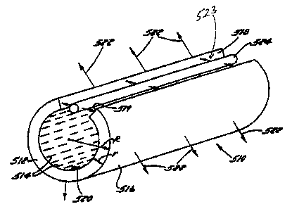
With reference now to Figure 9, a fiber optic luminaire 510 is formed from a
planar portion of optically conductive material formed into an annulus 512. In
this
regard, fiber optic luminaire 510 includes an inner surface 520 and an outer
surface
516. Inner surface 520 is formed with a plurality of axially oriented light
redirecting
structures 514, such as microprisms, microfacets, microgrooves and/or
micrometers.
Fiber optic luminaire 510 further includes an axial gap 523 defining a first
entrance
surface 518 and a second entrance surface 519. A light source 524 is disposed
along
axial gap 522 and provides a source of light energy. The light energy is
coupled into
annulus 512 via entrance surfaces 518 and 519 and is conducted along annulus
512
according to TIR. Annulus 512 is formed to a radius R and has a thickness r.
In order to
maintain TIR, the ratio R/r is maintained much greater than 1. In this manner,
light rays
are retained within and conducted radially about annulus 512 according to TIR.
A light
3o ray incident to a light redirecting structure 514 is reflected, without
scattering, through
outer surface 516 as a light ray 522. In a preferred arrangement, light
CA 02506711 1999-08-21
WO 00/11398 PCT/US99119147
-12-
redirecting structures 514 are distributed in accordance with Equations ( 1 ) -
( 13 ) for
providing a uniform light distribution.
With reference to Figure 10, and alternative awangement fiber optic luminaire
610 is formed from a planar portion of optically conductive material formed
into an
annulus 612. In this regard, fiber optic luminaire 610 includes an inner
surface 620
and an outer surface 616. Inner surface 620 is formed with a plurality of
radially
oriented light redir~ting structures 614, such as microprisms, microfacets,
microgrooves and/or micrometers. An end 622 is formed with an entrance surface
618. A light source 624 is disposed adjacent end 622 and provides a source of
light
energy. The light energy is coupled into annulus 612 at entrance surface 618
and
coupled axially along annulus 612 according to TIR Annulus 612 is formed to a
radius R and has a thickness r. In order to maintain TIR, the ratio R/r is
maintained
much greater than 1. In this mannex, light rays are ntainod within and
conducted
axially along annulus 612 according to TIR. A light ray incident to a light
redirecting
structure 614 is reflected, without scattering, through outer surface 616 as a
light ray
622. In a preferred arrangement, light redirecting structures 614 are
distributed in
accordance with Equations (1) - (13) for providing a uniform light
distribution. It
will be appreciated that according to a particular application, axial gap 626
may be
minimized such that fiber optic luminaire 610 is a substantially continuous
annular
cylinder.
5. Fiber Optic Luminaire Applications
Referring now to Figures 11 and 12, lock assembly 700 includes a fiber optic
luminaire 710 constructed in accordance with preferred embodiments of the
present
invention. Lock cylinder 700 includes a housing 702 formed with a thmugh bore
703
into which a lock cylinder 704 is secured. At an end 705 housing 702 includes
an
annular recess 706 into which fiber optic luminaire 710 formed in a
toroid'shape is
secured. Fiber optic luminaire 710 is constructed in accordance with preferred
embodiments of the present invention. In this manner, fiber optic luminaire
710
includes an optic fiber core formed with a plurality of light redirecting
structures and
a light entrance surface coupled to a light source. Lock assembly 700 may
preferably
be adapted for use in an automobile or in other locking applications where it
is
desirable to illuminate lock cylinder 704 for the user.
CA 02506711 1999-08-21
WO 00/11398 PCTNS99/19147
-13-
In Figure 13, an illuminated sign 800 is shown adapted with a plurality of
fiber
optic luminaires 802 - 810. Each of fiber optic luminaires 802 - 810 are
formed into
the shape of an illuminated letter and/or indicator, such as the letters "E",
"X", "I" and
"T" corresponding respectively to fiber optic luminaires 802 - 808 and an
arrow
S shape corresponding to fiber optic luminaire 810. Each fiber optic luminaire
802 -
810 is constructed in accordance with preferred embodiments of the present
invention.
In this manner, each fiber optic luminaire includes a fiber optic core, a
plurality of
light redirecting structures formed in an outer surface thereof, an entrance
surface
formed on the fiber optic core and coupled to a light source. For sign 800,
preferably
a single light source is provided and suitably coupled, such as by fiber optic
cable, to
each fiber optic luminaire 802 - 810.
Many changes and modifications could be made to the invention without
departing from the fair scope and spirit thereof. The scope of some changes is
discussed above. The scope of others will become apparent from the appended
claims.