Language selection

Search

Patent 2506832 Summary

Third-party information liability

Some of the information on this Web page has been provided by external sources. The Government of Canada is not responsible for the accuracy, reliability or currency of the information supplied by external sources. Users wishing to rely upon this information should consult directly with the source of the information. Content provided by external sources is not subject to official languages, privacy and accessibility requirements.

Claims and Abstract availability

Any discrepancies in the text and image of the Claims and Abstract are due to differing posting times. Text of the Claims and Abstract are posted:

  • At the time the application is open to public inspection;
  • At the time of issue of the patent (grant).
(12) Patent Application: (11) CA 2506832
(54) English Title: LIGHT EMITTING DIODE DISC OPTIC WITH HEAT SINK HOUSING
(54) French Title: OPTIQUE A DISQUE A DIODE ELECTROLUMINESCENTE AVEC BOITIER DE REFROIDISSEMENT
Status: Deemed Abandoned and Beyond the Period of Reinstatement - Pending Response to Notice of Disregarded Communication
Bibliographic Data
(51) International Patent Classification (IPC):
  • F21K 9/00 (2016.01)
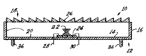
  • F21K 9/68 (2016.01)
  • F21K 9/69 (2016.01)
  • F21S 41/141 (2018.01)
  • F21S 43/14 (2018.01)
  • F21S 45/48 (2018.01)
  • F21V 29/70 (2015.01)
(72) Inventors :
  • COUSHAINE, CHARLES M. (United States of America)
  • TUCKER, MICHAEL (United States of America)
  • TESSNOW, THOMAS (United States of America)
(73) Owners :
  • OSRAM SYLVANIA, INC.
(71) Applicants :
  • OSRAM SYLVANIA, INC. (United States of America)
(74) Agent: SMART & BIGGAR LP
(74) Associate agent:
(45) Issued:
(22) Filed Date: 2005-05-09
(41) Open to Public Inspection: 2006-01-16
Availability of licence: N/A
Dedicated to the Public: N/A
(25) Language of filing: English

Patent Cooperation Treaty (PCT): No

(30) Application Priority Data:
Application No. Country/Territory Date
10/939,013 (United States of America) 2004-09-10
60/588,471 (United States of America) 2004-07-16

Abstracts

English Abstract


A lamp (10) has a cup-shaped body (12) with a bottom (14) with a sidewall (16)
defining
a top (18). The body (12) is thermally conductive. A reflective coating (20)
is provided
on the inside surface bottom (14) and side wall (16) for reflecting light from
a side
emitting LED (22) that is mounted on a thermally conductive, electrically
insulating
coupling (24) and is centered on the bottom (14). A lens (26) for directing
light emitted
from the LED (22) in a desired direction is provided and preferably is a
Fresnel optic.
The lens (26) can close the opening (18) or it can be formed as an integral
part of bottom
(14) or it can be added to the bottom (14). Alternatively, the lens (26) can
be solid with
the lens elements either external or internal. Electrical connections (28, 30)
to the LED
extend through the cup-shaped body (14).


Claims

Note: Claims are shown in the official language in which they were submitted.


Page 6
CLAIMS:
What is claimed is:
1. A lamp comprising:
a cup-shaped body having a planar bottom with an up-standing, peripheral side
wall defining a top;
a reflective coating on an inside surface of said planar bottom and side wall;
a single, side emitting LED mounted on a thermally conductive coupling
positioned substantially in the center of said planar bottom;
a lens for directing a beam of light emitted from said LED in a desired
direction;
and
electrical connections to said LED extending through said cup-shaped body.
2. The lamp of Claim 1 wherein said cup-shaped body is thermally conductive to
remove heat generated by the operation of said LED from said lamp.
3. The lamp of Claim 1 wherein said lens contains a Fresnel optic for
spreading said
beam of light generated when said LED is operating.
4. The lamp of Claim 3 wherein said lens closes said top.
5. The lens of Claim 3 wherein said lens is formed on said planar bottom.
6. The lamp of Claim 1 wherein said lamp includes circuitry providing
controlled
power to said LED.
7. The lamp of Claim 6 wherein said circuitry is positioned on the exterior of
said
cup-shaped body.

Description

Note: Descriptions are shown in the official language in which they were submitted.


CA 02506832 2005-05-09
Attorney Docket No.: 04-1-716
Page 2
LIGHT EMITTING DIODE DISC OPTIC WITH HEAT SINK HOUSING
001. This application claims priority from Provisional Patent Application No.
60/588,471 , filed July 16, 2004.
TECHNICAL FIELD
002. This invention relates to light sources and more particularly to light
sources
employing light emitting diodes (LED or LEDs) and more particularly to light
sources useful in the automotive field such as for headlights, taillights,
stoplights,
fog lights, turn signals, etc.
BACKGROUND ART
003. In the past, most automotive light sources have involved the use of
incandescent
bulbs. While working well and being inexpensive, these bulbs have a relatively
short life and, of course, the thin filament employed was always subject to
breakage due to vibration.
004. LEDs are solid state light sources and have achieved recent gains in
usage
because of their long life; however, it has been found that driving LEDs at
the
power required for automotive uses generates a considerable amount heat
requiring rather elaborate heat sinks for efficient operation.
005. Accordingly, it would be an advance in the art to simplify heat sinking
in LEDs,
particularly those for use in automotive applications.
DISCLOSURE OF INVENTION
006. It is, therefore, an object of the invention to obviate the disadvantages
of the prior
art.

CA 02506832 2005-05-09
Attorney Docket No.: 04-1-716
Page 3
007. It is another object of the invention to enhance LED light sources.
008. These objects are accomplished, in one aspect of the invention, by a lamp
comprising a cup-shaped body having a planar bottom with an up-standing,
peripheral side wall defining a top, a reflective coating on an inside surface
of the
planar bottom and side wall, a single, side emitting LED mounted on a
thermally
conductive coupling positioned substantially in the center of the planar
bottom, a
lens for directing a beam of light emitted from the LED in a desired
direction, and
electrical connections to the LED extending through the cup-shaped body.
009. In a preferred embodiment of the invention the cup-shaped body is
thermally
conductive thus eliminating the need for extra heat sinking.
BRIEF DESCRIPTION OF THE DRAWINGS
0010. Fig. 1 is a diagrammatic sectional view of an embodiment of the
invention;
0011. Fig. 2 is a diagrammatic sectional view of an alternate embodiment of
the
invention;
0012. Fig. 3 is a diagrammatic sectional view of yet another embodiment of the
invention;
0013. Fig. 4 is a diagrammatic view of yet another embodiment of the
invention; and
0014. Fig. 5 is a diagrammatic view of still another embodiment of the
invention.

CA 02506832 2005-05-09
Attorney Docket No.: 04-1-716
Page 4
BEST MODE FOR CARRYING OUT THE INVENTION
0015. For a better understanding of the present invention, together with other
and
further objects, advantages and capabilities thereof, reference is made to the
following disclosure and appended claims taken in conjunction with the above-
described drawings.
0016. Referring now to the drawings with greater particularity, there is shown
in Fig. 1 a
lamp 10 having a cup-shaped body 12 with a planar bottom 14 with an up-
standing, peripheral sidewall 16 defining a top 18.
0017. The body 12 is thermally conductive and preferably is a metal such as
aluminum.
A reflective coating 20 is provided on the inside surface of the planar bottom
14
and side wall 16 for reflecting light generated by a single, side emitting LED
22
that is mounted on a thermally conductive, electrically insulating coupling 24
and
is positioned substantially in the center of the planar bottom 14.
0018. A lens 26 for directing a beam of light emitted from the LED 22 in a
desired
direction is provided and preferably is a Fresnel optic. The lens 26 can close
the
opening 18 as shown in Fig. 1 or it can be formed as an integral part of
bottom 14
or it can be added to the bottom 14, as shown in Fig. 2. Alternatively, the
lens 26
can be solid with the lens elements external as shown in Fig. 4 or internal as
shown in Fig. S. Electrical connections 28, 30 to the LED extend through the
cup-shaped body 14.
0019. Controlled power can be provided to the LED through circuitry 32, for
example,
on a printed circuit board 34. The board 34 can be positioned within the
cavity
formed by the body 14 and the lens 26, when the lens 26 closes opening 18, or
it

CA 02506832 2005-05-09
Attorney Docket No.: 04-1-716
Page 5
can be positioned externally of the body 12 as shown in Fig. 3. A connector 38
for connection to a power source can also be provided.
0020. Mountings for the lamp 10, such as threaded studs 36, can be provided on
the
body 12 if desired.
0021. All of the embodiments shown and described provide a flat package with a
single
LED.
0022. While there have been shown and described what are present considered to
be the
preferred embodiments of the invention, it will be apparent to those skilled
in the
art that various changes and modifications can be made herein without
departing
from the scope of the invention as defined by the appended claims.
Representative Drawing
A single figure which represents the drawing illustrating the invention.
Administrative Status

2024-08-01:As part of the Next Generation Patents (NGP) transition, the Canadian Patents Database (CPD) now contains a more detailed Event History, which replicates the Event Log of our new back-office solution.

Please note that "Inactive:" events refers to events no longer in use in our new back-office solution.

For a clearer understanding of the status of the application/patent presented on this page, the site Disclaimer , as well as the definitions for Patent , Event History , Maintenance Fee  and Payment History  should be consulted.

Event History

Description Date
Inactive: IPC assigned 2021-10-20
Inactive: IPC removed 2021-10-20
Inactive: First IPC assigned 2021-10-20
Inactive: IPC assigned 2021-10-20
Inactive: IPC expired 2018-01-01
Inactive: IPC removed 2017-12-31
Inactive: IPC expired 2015-01-01
Inactive: IPC removed 2014-12-31
Application Not Reinstated by Deadline 2008-05-09
Time Limit for Reversal Expired 2008-05-09
Deemed Abandoned - Failure to Respond to Maintenance Fee Notice 2007-05-09
Application Published (Open to Public Inspection) 2006-01-16
Inactive: Cover page published 2006-01-15
Inactive: IPC assigned 2005-08-29
Inactive: First IPC assigned 2005-08-29
Inactive: Filing certificate - No RFE (English) 2005-06-15
Filing Requirements Determined Compliant 2005-06-15
Letter Sent 2005-06-15
Application Received - Regular National 2005-06-15

Abandonment History

Abandonment Date Reason Reinstatement Date
2007-05-09

Fee History

Fee Type Anniversary Year Due Date Paid Date
Application fee - standard 2005-05-09
Registration of a document 2005-05-09
Owners on Record

Note: Records showing the ownership history in alphabetical order.

Current Owners on Record
OSRAM SYLVANIA, INC.
Past Owners on Record
CHARLES M. COUSHAINE
MICHAEL TUCKER
THOMAS TESSNOW
Past Owners that do not appear in the "Owners on Record" listing will appear in other documentation within the application.
Documents

To view selected files, please enter reCAPTCHA code :


To view images, click a link in the Document Description column. To download the documents, select one or more checkboxes in the first column and then click the "Download Selected in PDF format (Zip Archive)" or the "Download Selected as Single PDF" button.

List of published and non-published patent-specific documents on the CPD .

If you have any difficulty accessing content, you can call the Client Service Centre at 1-866-997-1936 or send them an e-mail at CIPO Client Service Centre.


Document
Description 
Date
(yyyy-mm-dd) 
Number of pages   Size of Image (KB) 
Description 2005-05-09 4 132
Abstract 2005-05-09 1 23
Drawings 2005-05-09 2 61
Claims 2005-05-09 1 31
Representative drawing 2005-12-20 1 10
Cover Page 2006-01-06 1 43
Courtesy - Certificate of registration (related document(s)) 2005-06-15 1 114
Filing Certificate (English) 2005-06-15 1 158
Reminder of maintenance fee due 2007-01-10 1 111
Courtesy - Abandonment Letter (Maintenance Fee) 2007-07-04 1 176