Note: Descriptions are shown in the official language in which they were submitted.
CA 02506936 2005-05-20~ I,~T~I2003/000865
T'tae v,nre~is~ &~s~e~!~ ~~~~~e
~~°a ~~A~~~~=~~~;~:~4 ~,ryu ,. :~~~,~~ Zg_12-2004
... ,~ ..
1
POLYHEDRAL ARRAY HEAT TRANSFER TUBE
The present invention relates to tubes used in heat exchangers and more
particularly, the invention relates to a heat exchanger tube having an
internal
surface that is capable of enhancing the heat transfer performance of the
tube.
BACKGROUND OF THE INVENTION
The heat transfer performance of a tube having surface enhancements is
known by those skilled in the art to be superior to a plain walled tube.
Surface
enhancements have been applied to both internal and external tube surfaces,
including ribs, fins, coatings, and inserts, and the like. All enhancement
designs
attempt to increase the heat transfer surface area of the tube. Most designs
also attempt to encourage turbulence in the fluid flowing through or over the
tube in order to promote fluid mixing and break up the boundary layer at the
surface of the tube.
A large percentage of air conditioning and refrigeration, as well as engine
cooling, heat exchangers are of the plate fin and tube type. In such heat
exchangers; the tubes are externally enhanced by use of plate fins affixed to
the exterior of the tubes. The heat exchanger tubes also frequently have
internal heat transfer enhancements in the form of modifications to the
interior
surface of the tube.
In a significant proportion of the total length of the tubing in a typical
plate fin
and tube air conditioning and refrigeration heat exchanger, the refrigerant
exists
in both liquid and vapor states. Below certain flow rates and because of the
variation in density, the liquid refrigerant flows along the bottom of the
tube and
the vaporous refrigerant flows along the top. Heat transfer performance of the
tube is improved if there is improved intermixing between the fluids in the
two
states, e.g., by promoting drainage of liquid from the upper region of the
tube in
A;lwIEl~IDED S~-IEET
CA 02506936 2005-05-20 _
' -t-~~ rmedis ~a~~'~~~~ ~I P~T/I'' I2003/000865
~'E° E~t~reoa~i~°,~~:~ ~~~r ~'' ,.,
28-12-2004
2
a condensing application or encouraging liquid to flow up the tube in a wall
by
capillary action in evaporating application.
In order to reduce the manufacturing costs of the heat exchangers, it is also
desirable to reduce the weight of the heat transfer tube while maintaining
performance.
Internal enhancement of the tube increases the heat transfer coefficient of
the
heat exchanger. Increasing this coefficient increases the amount of heat
exchanged if the heat exchanger remains at the original size and volume or
creates the possibility of reducing the size of the heat exchanger while
maintaining performance.
Accordingly, what is needed is a heat transfer tube that provides superior
performance for condensing andlor evaporating applications and that offers
practical and economical features to end users.
SUMMARY OF THE INVENTION
The present invention meets the above-described need by providing a heat
exchanger tube that comprises a tubular member having a longitudinal axis and
having an inner surface that is divided into at least two regions along the
circumferential direction. A first plurality of polyhedrons is formed on the
inner
surface along at least one polyhedral axis. Each of the polyhedrons has four
sides projecting from the surface. The polyhedrons have first and second faces
disposed parallel to the polyhedral axis and have third and fourth faces
disposed oblique to the polyhedral axis. The polyhedral axis is disposed at a
first angle with respect to the longitudinal axis of the tube. A second
plurality of
polyhedrons is formed on the inner surface adjacent to the first plurality of
polyhedrons. The second plurality of polyhedrons is disposed along at least
one
polyhedral axis. Each of the polyhedrons has four sides. projecting from the
surface. The polyhedrons have first and second faces disposed parallel to the
AhvIENDED SHEET
CA 02506936 2005-05-20
' ~.~~ ~,~,.Q~oS~~.~~PCT/FI20031000865
~~-e a~~~~°a~~~~~~T~~ ~.~~=~a..~i~~,~ ~~ 2g_12-2004
3
25
polyhedral axis and have third and fourth faces disposed oblique to the
polyhedral axis. The polyhedral axis is disposed at a second angle with
respect
to the longitudinal axis of the tube. The orientation of the second angle is
opposite to the orientation of the first angle. For a typical round tube there
may
5 be four equal sized regions. However as will be described below, the regions
may have different sizes and there may be multiple regions totaling more than
four.
BRIEF DESCRIPTION OF THE DRAWINGS
The invention is illustrated in the drawings in which like reference
characters
designate the same or similar parts throughout the figures of which:
Figure 1 is a detailed view of an individual portion of the wall of the heat
exchanger;
Figure 2 is a perspective view of two adjacent portions of the wall of the
heat
exchanger tube of the present invention laid flat and including the individual
portion shown in Fig. 1;
Figure 3 is a graph showing the relative performance of the tube of the
present
invention compared to prior art tubes with regard to heat transfer when the
tube
is used in a condensing application; and,
Figure 4 is a graph showing the relative performance of the tube of the
present
invention compared to prior art tubes with regard to pressure drop.
DETAILED DESCRIPTION
Throughout this specification the term polyhedron is used and it is to be
defined
as a. solid formed by substantially planar faces.
The tube of the present invention is preferably formed out of copper, copper
alloy, or other metallic or non-metallic material. The tube may be round,
oval, or
even flat in cross-section. The tube may be cylindrical with an outside
.diameter,
~.lVIEI~TD~D SHEET
CA 02506936 2005-05-20
' ~.~~ e,~,e~~s~ '~~~ ~~ ~°°'~ PCT/FI20031000865
,. ~~'-T ac~~e~~~~~r~~~:n ,~~a~~'f" '~r~ 2g_12-2004
4
inside diameter and corresponding wall thickness. The internal surface of the
tube is formed with the internal surface enhancement of the present invention.
The heat exchanger tube of the present invention may be formed by roll
embossing the enhancement pattern on one surface on a strip of material
before roll forming and seam welding the strip into a tube.
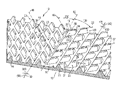
In Fig. 1, a portion 11 of tube 10 is laid flat and shown with surface
enhancement 13. Extended outward from wall 16 are a plurality of polyhedrons
19. The polyhedrons 19 are disposed in a plurality of rows 20 with each row
disposed along an axis 22. The rows 20 have a angle 100 (Fig. 2) with respect
to the longitudinal axis 50 of the tube 10, as will be described in greater
detail
below.
A first planar face 25 and a. second planar face 28 are disposed parallel to
the
axis 22. A third planar face 31 and a fourth planar face 34 are disposed at an
angle oblique to the axis 22. The polyhedrons 19 are disposed on the wall 16
at
a distance d between center lines of the adjacent rows. Distance d can be in
the range of 0.011 inches to 0.037 inches. The faces 31 and 34 form an apex
angle I~ that is between 5-50 degrees. The faces 31 and 34 extend downward
toward the inner wall 16 of the tube 10 and may extend from twenty to one
hundred percent of the height of the polyhedron 19. The length of the
polyhedrons 19 is I. The length I may be from 0.005 to 0.025 inches. The third
and fourth faces 31 and 34 make an angle 75 with respect to the axis 22 of the
rows of polyhedrons 19. The polyhedrons have height H and have a maximum
width w. The width w is in the range of 0.004 to 0.01 inches. The polyhedrons
19 have an angle 12 between faces 25 and 28. Angle 12 is in the range of 5 to
50
degrees. For all sizes of tubing the number of polyhedrons per 360 degree arc
is determined by the pitch or d defined above. The surface enhancement 13
typically provides between 500 to 10,000 polyhedrons per square inch.
AI~I~NBEI) ~H~~'T
CA 02506936 2005-05-20
~'~~ e~~ai~~ ~'~~'~~ ~~~~~ pCT/FI2003/000865
~~s~ ~~~:~'B'h'T.'~3r:r,~rw'."r' !°-.~9~..,:y";»r~'_(~,.~
28-12-2004
For the present invention, the ratio of polyhedron height to outside diameter
is
in the range of .005 to.05.
Turning to Fig. 2, portion 11 and an adjacent portion 44 are laid out flat and
5 shown in one arrangement relative to the longitudinal axis 50 of the tube
10. In
portion 11, the axis 22 of the polyhedrons 19 is disposed at an angle 100 with
respect to the axis 50 of tube 10. The angle 100 may be between 5 and 40
degrees. In one embodiment, the angle 100 is approximately 15 degrees.
Portion 44 is disposed adjacent to portion 11. The polyhedrons 19 are
constructed in the same manner as described above. The difference between
portion 11 and portion 44 is the orientation of the axis 46 of the rows of
polyhedrons 19 relative to the axis 50 of tube 10. In the embodiment shown,
the
axis 46 is disposed at an angle 200 that is between 5 and 40 degrees and is
usually disposed at an angle that is equal and opposite to angle 100. In one
embodiment, the angle 200 is 15 degrees. While the adjacent portions 11 and
44 may have symmetrical angles 100 and 200, an asymmetrical angle is also
suitable. Also, portions 11 and 44 are shown in Fig. 2 having approximately
equal size. The area of portions 11 and 44 does not have to be equal. For a
typical round tube there are usually four equal-sized portions.
Faces 31 and 34 of portion 11 are disposed along an axis 150 that makes an
angle 300 with respect to the axis 50. Faces 31 and 34 of portion 44 are
disposed along an axis 250 that makes an angle 400 with respect to the axis
50. Angles 300 and 400 are less than 10 degrees and are equal. It has been
found that the angles 300 and 400 may be 0 degrees (axial). Also, the angles
300 and 400 can be 7 degrees. This arrangement reduces the pressure drop of
the tube 10.
Enhancement 13 may be formed on the interior of tube wall 16 by any suitable
process. In the manufacture ~of seam welded metal tubing using automated
high-speed processes an effective method is to apply the enhancement pattern
Al~~l'~D~D SHE~'T
CA 02506936 2005-05-20
' 't°a°~~ ~~~a~~ ~~~~~~ PCT/FI2003/000865
~~°E 8ra~e~ro~.t~~~.~a R~.~y:..,.;n,~~°a
28-12-2004
6
13 by roll embossing on one surface of a metal strip before the strip is roll
formed into a circular cross section and seam welded into tube 10. This may be
accomplished by positioning two roll embossing stations in sequence in a
production line for roll forming and seam welding metal strips into tubing.
The
stations would be positioned between the source of supply of unworked metal
strip and the portion of the production line where the strip is roll formed
into a
tubular shape. Each embossing station has a pattern enhancement roller
respectively and a backing roller. The backing and pattern rollers in each
station are pressed together with sufficient force by suitable means (not
shown), to cause the pattern surface on one of the rollers to be impressed
into
the surface on one side of the strip thus forming the longitudinal sides of
the
polyhedrons. The third and fourth faces 31 and 34 will be formed by a second
roller having a series of raised projections that press into the polyhedrons
19.
If the tube is manufactured by roll embossing, roll forming, and seam welding,
it
is likely that there~will be a region along the line of the weld in the
finished tube
10 that either lacks the enhancement configuration that is present around the
remainder of the tube 10 in a circumference, due to the nature of the
manufacturing process, or has a different enhancement configuration. This
region of different configuration will not adversely affect the thermal or
fluid flow
performance of the tube 10 in a significant way.
Turning to FIG. 3, h represents the heat transfer coefficient, IE represents
tubing with internal enhancements, and "smooth" represents plain tubing. The
curves in FIG. 3 illustrate the relative condensing performances
(h(IE)/h(smooth)) of three different internally enhanced tubes compared to a
tube having a smooth inner surface over a range of mass flow rate of
refrigerant R-22 through the tubes. Tube A is one embodiment of the present
invention. Tube B represents a prior art tube having an inner surface
enhancement, which is generally referred to as a crosshatch enhancement.
Tube C is another prior art tube, which is generally referred to as a
herringbone
enhancement. The graph of FIG. 3 illustrates that condensation heat transfer
AMEf'~f)ED SHEET
' ~'6~e ~vvec~is~ P~~~~ a~ ~~~~*4~e,.
~~~. 0~~~.~~db~.~.r~,,~n ~~.~,~~,~p~_ .: ~~ PCT/FI2003/000865
'~ 28-12-2004
7
performance of the present invention far exceeds the performance of the
crosshatch enhancement and is slightly better than the herringbone
enhancement. Accordingly, the present invention provides better performance
at equal weight and equal performance at a reduced weight therefore reducing
the costs to the end user.
Turning to FIG. 4, the curves show the relative performance with regard to
pressure drop of the above described tubes A, B, and C, over a range of mass
flow rates of refrigerant R-22 through the tube. The graph of FIG. 4 indicates
that condensation pressure drop of the present invention is more than 20%
below the pressure drop of the herringbone enhancement, in most of the flow
rate range.
The polyhedral array of the present invention creates added turbulence by
directing fluid streams flowing over the surface to impact each other. If the
flow
is vapor-liquid two phases, it generates enough turbulence so that the vapor
and liquid interfacial tear is much stronger which results in near perfect
vapor-
liquid mixing. .The tube 10 of the present invention performs very well in
condensation heat transfer, which requires strong vapor-liquid interfacial
mixing.
While the invention has been described in connection with certain
embodiments, it is not intended to limit the scope of the invention to the
particular forms set forth, but, on the contrary, it is intended to cover such
alternatives, modifications, and equivalents as may be included within the
spirit
and scope of the invention as defined by the appended claims.
~lVI~l~D~D SHEET
CA 02506936 2005-05-20