Language selection

Search

Patent 2507556 Summary

Third-party information liability

Some of the information on this Web page has been provided by external sources. The Government of Canada is not responsible for the accuracy, reliability or currency of the information supplied by external sources. Users wishing to rely upon this information should consult directly with the source of the information. Content provided by external sources is not subject to official languages, privacy and accessibility requirements.

Claims and Abstract availability

Any discrepancies in the text and image of the Claims and Abstract are due to differing posting times. Text of the Claims and Abstract are posted:

  • At the time the application is open to public inspection;
  • At the time of issue of the patent (grant).
(12) Patent: (11) CA 2507556
(54) English Title: A TRAILER FOR TOWING AFTER A TOWING VEHICLE, A SYSTEM COMPRISING A TRAILER AND A TOWING VEHICLE, AND A METHOD OF STEERING A TRAILER AROUND A TURNING POINT
(54) French Title: REMORQUE POUR VEHICULE TRACTANT UNE REMORQUE, SYSTEME REMORQUE/VEHICULE TRACTEUR, ET PROCEDE DE CONDUITE DE REMORQUE AUTOUR D'UN POINT DE VIRAGE
Status: Expired and beyond the Period of Reversal
Bibliographic Data
(51) International Patent Classification (IPC):
  • B62D 13/00 (2006.01)
  • A1M 7/00 (2006.01)
  • B62D 13/02 (2006.01)
  • B62D 13/04 (2006.01)
(72) Inventors :
  • NEJSUM, LARS (Denmark)
(73) Owners :
  • EXEL INDUSTRIES SA
(71) Applicants :
  • EXEL INDUSTRIES SA (France)
(74) Agent: MOFFAT & CO.
(74) Associate agent:
(45) Issued: 2011-06-21
(86) PCT Filing Date: 2003-12-02
(87) Open to Public Inspection: 2004-06-17
Examination requested: 2005-05-26
Availability of licence: N/A
Dedicated to the Public: N/A
(25) Language of filing: English

Patent Cooperation Treaty (PCT): Yes
(86) PCT Filing Number: PCT/DK2003/000826
(87) International Publication Number: DK2003000826
(85) National Entry: 2005-05-26

(30) Application Priority Data:
Application No. Country/Territory Date
PA 2002 01860 (Denmark) 2002-12-02

Abstracts

English Abstract


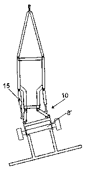
The invention relates to trailer (1) for towing after a towing after a towing
vehicle,
said trailer (1) comprising a frame (3) configured for carrying a load and
having a
front end with a coupling (5) configured for connecting the trailer (1) to the
towing
vehicle and allowing that the trailer (1) and the towing vehicle are able to
assume
mutually angular positions during turning about a turning point O; and a rear
end.
The trailer also has a separate wheel frame (8) that is connected to the frame
(3)
by means (10) that allow a relative turning of the frame in relation to the
wheel
frame (8) during turning of the trailer about the turning point, said wheel
frame (8)
comprising oppositely arranged wheels (4) that support the trailer (1) during
the
towing and that are arranged at a distance from each other close to a
respective
longitudinally extending side of the frame (3); and actuator means (15) for
producing said relative turning of the frame (3). The invention is
characterized in
that the connecting means (10) also allow a controlled transversal movement of
the frame (3) in a direction towards or away from said turning point (O)
simultaneously with said relative turning of the frame (3); and that the
trailer (1)
comprises actuator means (15) for producing said transversal movement of the
frame (3).


French Abstract

L'invention concerne une remorque (1) pour véhicule tractant une remorque, qui comprend un châssis (3) capable de supporter une charge et comportant une extrémité avant à organe de couplage (5) pour le couplage de la remorque (1) au véhicule tracteur, permettant différentes positions angulaires mutuelles inhérentes à la conduite d'un virage autour d'un point de virage O. La remorque comprend aussi une extrémité arrière. Par ailleurs, elle comporte un cadre pour roues (8) relié au châssis (3) au moyen d'un organe de connexion (10) permettant au châssis d'accomplir une rotation relative par rapport au cadre pour roues (8) durant le virage de la remorque autour du point de virage. Le cadre pour roues (8) comprend des roues opposées (4) qui soutiennent la remorque (1) lorsque celle-ci est tractée et qui sont espacées mutuellement en étant situées à proximité d'un côté longitudinal du châssis. Enfin, la remorque comporte un actionneur (15) qui engage la rotation relative du châssis (3). L'organe de connexion (10) permet un mouvement transversal contrôlé du châssis (3) dans une direction de rapprochement ou d'éloignement par rapport au point de virage (O), simultanément avec la rotation relative du châssis (3). Enfin, l'actionneur (15) de la remorque (1) permet d'engager le mouvement transversal du châssis (3).

Claims

Note: Claims are shown in the official language in which they were submitted.


THE EMBODIMENTS OF THE INVENTION IN WHICH AN EXCLUSIVE
PROPERTY OR PRIVILEGE IS CLAIMED ARE DEFINED AS FOLLOWS:
1. A trailer for towing after a towing vehicle, said trailer comprising:
a) a frame configured for carrying a load and having:
i) a front end with a coupling configured for connecting said trailer to said
towing vehicle and allowing that said trailer and said towing vehicle are able
to assume
mutually angular positions during turning about a turning point 0; and
ii) a rear end; and
b) a separate wheel frame that is connected to said frame by means of
connecting means that allow a relative turning of said frame in relation to
said wheel
frame during said turning about a turning point (0), said wheel frame
comprising
oppositely arranged wheels that support said trailer during said towing and
that are
arranged at a distance from each other close to a respective longitudinally
extending
side of said frame
wherein said connecting means also allow a controlled transversal movement of
said frame in relation to said wheel frame in a direction towards or away from
said
turning point (0) simultaneously with said relative turning of the frame; and
actuator means are provided for producing said relative turning of said frame,
and
for producing said transversal movement.
2. A trailer according to claim 1, wherein said wheels are arranged at said
rear end
of said trailer opposite said coupling.
3. A trailer according to claim 1 or 2, wherein said wheel frame is arranged
behind
said rear end of said frame in order to thus constitute a rear end of said
trailer.
4. A trailer according to any one of claims 1 to 3, wherein said wheel frame
carries
a fold boom sprayer.

5. A trailer according to any one of claims 1 to 4, wherein said load is a
liquid
container.
6. A trailer according to claim 5, wherein said container extends until or
beyond said
rear end of said frame; and that said wheels are arranged at a rear end of
said trailer
opposite said coupling.
7. A trailer according to any one of claims 1 to 6, wherein said wheels are
also
arranged for turning about an essentially vertical axis in relation to said
wheel frame; and
that wheel turning actuator means are coupled to said wheel frame to produce
said
turning of said wheel about said essentially vertical axis in relation to said
wheel frame.
8. A trailer according to any one of claims 1 to 7, wherein said connecting
means are
constituted of at least two arms that are pivotally connected to said frame
and said wheel
frame, respectively, and that said connecting means constitute a part of a
trapezoidal
mechanism for controlling said movement of said frame along a curve track in
relation
to said wheel frame.
9. A trailer according to any one of claims 1 to 7, wherein said connecting
means
comprise a journaling for said wheel frame with slide steering for controlling
the
movement of said frame along a curve line in relation to said wheel frame.
10. A trailer according to any one of claims 1 to 9, wherein a control unit
with a
memory produces, via said actuator means, a predetermined fixed setting of
said frame
in relation to said wheel frame in correspondence with an angle position
between said
towing vehicle and said wheel frame.
11. A trailer according to any one of claims 1 to 10, wherein said actuator
means are
connected to said frame, to said wheel frame or to said connecting means.

12. A system comprising a towing vehicle and a trailer according to any one of
claims
1 to 9, wherein a control unit with a memory produces, via said actuator
means, a
predetermined fixed setting of said frame in relation to said wheel frame in
correspondence with an angle position between said towing vehicle and said
wheel
frame.
13. A system according to claim 12, wherein mutual distances transversal to a
direction of driving between wheels of said towing vehicle and between said
wheels of
said trailer are essentially identical.
14. A system according to claim 12 or 13, wherein said control unit is
configured for
ensuring that at least one set of wheels on said towing vehicle and said
wheels of said
trailer move(s) along matching curve lines during turning about said turning
point O.
15. A method of steering a trailer around a turning point (0), said trailer
being towed
by a towing vehicle, wherein said trailer comprises:
a) a frame configured for carrying a load and having:
i) a front end with a coupling configured for connecting said trailer to said
towing vehicle and allowing that said trailer and said towing vehicle are able
to assume
mutually angular positions during turning about a turning point 0; and
ii) a rear end;
b) a separate wheel frame that is connected to said frame by means of
connecting means that allow a relative turning of said frame in relation to
said wheel
frame during said steering, said wheel frame comprising oppositely arranged
wheels that
support said trailer during said towing and that are arranged at a distance
from each
other close to a respective longitudinally extending side of said frame; and
c) actuator means for producing said relative turning of said frame;
wherein by means of said actuator means, a transversal movement of said frame
is produced in relation to said wheel frame in a direction towards or away
from said
turning point (0) simultaneously with a relative turning of said frame in
relation to said
wheel frame.

Description

Note: Descriptions are shown in the official language in which they were submitted.


CA 02507556 2009-05-11
A trailer for towing after a towing vehicle, a system comprising a trailer and
a towing
vehicle, and a method of steering a trailer around a turning point
The present invention relates to a trailer for towing behind a towing vehicle.
Thus, as a starting point the trailer according to the invention comprises a
frame configured for
carrying a load and having a front end with a coupling for connecting the
trailer to the towing
vehicle in such a manner that the trailer and the towing vehicle are able to
assume mutual angle
positions during turning around a turning point, and a rear end. Besides, the
trailer comprises
a separate wheel frame that is connected to the frame by means of connecting
means that allow
a relative turning of the frame in relation to the wheel frame during said
turning around a turning
point. This wheel frame comprises oppositely arranged wheels that support the
trailer during the
towing and are arranged at a distance in relation to each other near a
respective longitudinally
extending side of the frame. Additionally, the trailer has actuator means for
producing said
relative turning of the frame. It being difficult to define the notion of
actual parallel longitudinally
extending sides of the frame, said longitudinally extending sides can be
perceived as areas
situated to each side of a longitudinally extending line of symmetry for the
frame that extends
from the front end of the frame to the rear end of the frame.
Trailers of this type are already known from eg BE 473 218 and EP 350 008. It
is a common
feature of these trailers that it is possible to actively influence and modify
the movement of the
trailer, when the trailer is moved through curves by means of the towing
vehicle.

CA 02507556 2005-05-26
WO 2004/050457 PCT/DK2003/000826
2
For instance, there may be a need for performing such influence when a
towing vehicle and a trailer are to move along parallel tracks on a field and
when, to this end, the towing vehicle and the trailer have to turn at the end
of
the field. In particular in that context it is important that the wheels of
the
trailer do not interfere with an extra track on the field, which may harm the
crop, but rather that the wheels of the trailer accurately follow the wheel
tracks that were initially established in the field or generated during
driving by
the preceding towing vehicle. The mutual spacing transversally to the driving
direction between the wheels on the trailer is, of course, as a starting point
selected to be in correspondence with the corresponding space between the
wheels of the towing vehicle, thereby avoiding the generation of an additional
wheel track during straight-ahead operation. However, during the turning an
active influence has to be exerted on the trailer to avoid generation of
additional wheel tracks.
By the construction of such trailers it is necessary to take into account the
stability problems that may arise, in particular in case the trailer is to
carry a
high load. The problems are further exacerbated if the load is constituted by
a high tank containing liquids that may splash to the effect that the risk of
the
trailer toppling on its side during the turning is further increased. This
problem
is of particular relevance when the trailer constitutes a field sprayer and a
fold
boom sprayer.
Since the distance between the wheels on the trailer is, as mentioned,
determined by the corresponding distance between the wheels of the towing
vehicle, the system chosen for influencing the turning of the trailer around
the
turning point may impose limitations to the options available to the
constructer when the shape of the frame is to be determined. This will also
be the case inasmuch as the load of the trailer is concerned, including eg the
configuration of the liquid tank, where a field sprayer may be concerned that
constitutes the load. The liquid tank and the frame must thus be shaped

CA 02507556 2005-05-26
WO 2004/050457 PCT/DK2003/000826
3
specifically for allowing space for the movement of the wheels during turning
of the wheel frame. It follows from this that the tank of such trailers must
be
made even narrower at the bottom than is shown in Figure 1 of EP 862 855,
where the wheel axles of the trailer are fixedly mounted. In order to
compensate for such reduction in dimensions at the bottom of the tank, the
constructor will often strive to increase the height of the liquid tank, which
may, however, lead to quite serious problems with stability, in particular
during turning around a turning point.
It is an object of the invention to provide a trailer that can be steered
though
curves and that reduces the limitations that may be imposed on the shape of
the load. This is accomplished as featured in claim 1 in that the connecting
means mentioned above are configured such that they also allow a
controlled, transversal movement of the frame in relation to the wheel frame
in a direction towards or away from said turning point, ie transversally to
the
direction of driving, simultaneously with said relative turning of the wheel
frame taking place; and that the trailer comprises actuator means for
producing said transversal movement of the frame. It will be understood that
the trailer may be provided with more than one wheel frame of the type
described, albeit at present a configuration with one wheel frame is
preferred.
Advantageous embodiments will appear from the dependent claims. The
trailer can thus be an integral part of a tool, such as an agricultural
implement, where the load is a receptacle for spraying liquid that extends
very closely to the rearmost end of the trailer, the wheels being arranged at
the rear end of the trailer, opposite the coupling. The connecting means may
in a simple manner be configured as at least two arms that are pivotally
connected to the frame and the wheel frame, respectively, and that constitute
a trapezoidal mechanism for controlling the movement of the wheel frame
along a curve track.

CA 02507556 2005-05-26
WO 2004/050457 PCT/DK2003/000826
4
The invention also relates to a system comprising a combination of the trailer
and a towing vehicle and a method of steering a trailer through curves.
In the following, the invention will be explained in further detail with
reference
to the drawing, wherein
Figures 1 a and 1 b show how the wheels on a trailer can be steered when the
trailer is towed after a towing vehicle and when it is desired that the
trailer
should follow the track of the towing vehicle;
Figures 2a, 2b and 2c show respective positions for the trailer according to
the invention during movements through curves having different radii; and
Figure 3 shows an alternative embodiment of the trailer, wherein the wheels
have a further degree of freedom.
In Figures 1 a and 1 b, two solutions known from BE 473 218 are represented
for controlling the wheels of a trailer and it will appear how, in order to
ensure
that the wheel tracks of the trailer follow the wheel tracks of the towing
vehicle, it is necessary to see to it that the wheels on the wheel frame are
at
any time perpendicular to a straight line that extends to the turning point 0.
By the present invention the latter condition must also be complied with in
those cases where it is desired that the wheel tracks of the trailer are to
follow the wheel tracks of the towing vehicle during turning around a turning
point 0, and it can be ensured by providing, either on the towing vehicle or
on the trailer, a control unit with a memory that will, via actuator means,
produce a predetermined setting of the frame in relation to the wheel frame,
as will be explained below.

CA 02507556 2005-05-26
WO 2004/050457 PCT/DK2003/000826
Figures 2a, 2b and 2c show a trailer 1 according to the invention. Preferably
the trailer 1 is connected directly to the towing hook on the towing vehicle
via
a coupling in the form of a tow ring at the front end of the frame 3. The
wheel
frame 8 of the trailer 1 that carries the wheels that support the trailer is
5 movably mounted on the frame 3 at the rear end thereof, in such a manner
that the frame may - in relation to the wheel frame 8 - be forced to turn and
simultaneously forced to swing sideways and outwards transversally to the
direction of driving towards or away from the turning point 0 in relation to
the
wheel frame 8. When the combined vehicle drives straight ahead, the wheels
4 are, of course, parallel with the wheels (not shown) of the towing vehicle,
and the wheel frame 8 extends in extension of the frame 3 behind same.
When the towing vehicle turns and it is thus time to swing around a turning
point 0, the frame 3 will be conveyed to the side, while simultaneously the
frame turns in relation to the wheel frame 8.
In order to obtain this translatory and rotary movement of the frame 3, the
frame 3 is preferably connected to the wheel frame 8 via connecting means
10 in the form of a trapezoidal connection comprising two arms of equal
lengths, 10', 10", each of which is pivotally connected to the frame 3 and the
wheel frame 8, respectively. Hereby the frame 3 is controlled by the
particular
pattern of movement that follows from the freedom of movement of the
trapezoidal connection. Figure 2a shows that the. arms 10', 10" converge in a
direction towards the frame 3, but it may very well be an option to have an
alternative configuration, wherein the arms 10', 10" converge in a direction
towards the wheel frame 8. It may in some cases entail a favourable increase
of the trailer stability during turning.
When the towing vehicle starts to move, actuator means 15 in the form of eg
hydraulic cylinders 15', 15"control the movement of the frame 3, to the effect
that the frame 3 adapts to the desired position. The control of the hydraulic

CA 02507556 2005-05-26
WO 2004/050457 PCT/DK2003/000826
6
cylinders 15', 15" may occur in correspondence with a detected angle
between the towing vehicle and the wheel frame 8.
When, in particular in connection with field sprayers, where the frame 3
carries a large liquid tank, it is a point of interest to accomplish a
swinging of
the frame 3 and not merely a turning of the wheel frame 8 or of the axle 8' of
the wheels 4, it is due to the fact that such turning on its own may limit the
dimensions of the tank transversally to the frame 3 at the bottom at the
wheels 8 and on the connecting rods (19) between the wheel frame 8 and the
beam 20, as the wheels may bump against the tank and/or the connecting
bars 19.
It is preferred that the axes of rotation of the wheels 4 in relation to the
wheel
frame 8 are fixed as shown in Figures 2a-2c, and that thus the freedom of
movement resides primarily in the movability of the wheel frame 8 in relation
to the frame 3.
In some situations, as shown specifically in Figure 3 it may be expedient to
build in a system for turning the wheels 4 in relation to the wheel frame 8,
eg
if the remaining constructive elements on the frame 3 prevent a sufficiently
large stewing of the wheel frame 8. This turning movement may be generated
eg by means of a system of actuator means as shown by the reference
numeral 15"', in addition to the actuator means 15', 15" (not shown in Figure
3).
In Figures 2a-c and Figure 3, the wheel frame 8 is shown with an elongate
beam 20 at the rear. This beam 20 may in a convenient manner support a
boom sprayer optionally with an associated air blower device, as shown in
WO 95/16347.

Representative Drawing
A single figure which represents the drawing illustrating the invention.
Administrative Status

2024-08-01:As part of the Next Generation Patents (NGP) transition, the Canadian Patents Database (CPD) now contains a more detailed Event History, which replicates the Event Log of our new back-office solution.

Please note that "Inactive:" events refers to events no longer in use in our new back-office solution.

For a clearer understanding of the status of the application/patent presented on this page, the site Disclaimer , as well as the definitions for Patent , Event History , Maintenance Fee  and Payment History  should be consulted.

Event History

Description Date
Time Limit for Reversal Expired 2023-06-02
Letter Sent 2022-12-02
Letter Sent 2022-06-02
Letter Sent 2021-12-02
Common Representative Appointed 2019-10-30
Letter Sent 2017-04-13
Inactive: Single transfer 2017-04-04
Inactive: Office letter 2016-08-22
Inactive: Single transfer 2016-08-16
Grant by Issuance 2011-06-21
Inactive: Cover page published 2011-06-20
Pre-grant 2011-04-08
Inactive: Final fee received 2011-04-08
Notice of Allowance is Issued 2010-10-18
Letter Sent 2010-10-18
4 2010-10-18
Notice of Allowance is Issued 2010-10-18
Inactive: Approved for allowance (AFA) 2010-10-07
Amendment Received - Voluntary Amendment 2010-03-25
Inactive: S.30(2) Rules - Examiner requisition 2009-09-25
Amendment Received - Voluntary Amendment 2009-05-11
Inactive: S.30(2) Rules - Examiner requisition 2008-11-13
Inactive: IPC from MCD 2006-03-12
Letter Sent 2006-01-13
Reinstatement Requirements Deemed Compliant for All Abandonment Reasons 2005-12-29
Deemed Abandoned - Failure to Respond to Maintenance Fee Notice 2005-12-02
Letter Sent 2005-09-22
Inactive: Cover page published 2005-09-07
Letter Sent 2005-08-22
Inactive: Acknowledgment of national entry - RFE 2005-08-22
Inactive: Single transfer 2005-07-07
Application Received - PCT 2005-06-23
National Entry Requirements Determined Compliant 2005-05-26
Request for Examination Requirements Determined Compliant 2005-05-26
All Requirements for Examination Determined Compliant 2005-05-26
Application Published (Open to Public Inspection) 2004-06-17

Abandonment History

Abandonment Date Reason Reinstatement Date
2005-12-02

Maintenance Fee

The last payment was received on 2010-12-01

Note : If the full payment has not been received on or before the date indicated, a further fee may be required which may be one of the following

  • the reinstatement fee;
  • the late payment fee; or
  • additional fee to reverse deemed expiry.

Patent fees are adjusted on the 1st of January every year. The amounts above are the current amounts if received by December 31 of the current year.
Please refer to the CIPO Patent Fees web page to see all current fee amounts.

Owners on Record

Note: Records showing the ownership history in alphabetical order.

Current Owners on Record
EXEL INDUSTRIES SA
Past Owners on Record
LARS NEJSUM
Past Owners that do not appear in the "Owners on Record" listing will appear in other documentation within the application.
Documents

To view selected files, please enter reCAPTCHA code :


To view images, click a link in the Document Description column (Temporarily unavailable). To download the documents, select one or more checkboxes in the first column and then click the "Download Selected in PDF format (Zip Archive)" or the "Download Selected as Single PDF" button.

List of published and non-published patent-specific documents on the CPD .

If you have any difficulty accessing content, you can call the Client Service Centre at 1-866-997-1936 or send them an e-mail at CIPO Client Service Centre.


Document
Description 
Date
(yyyy-mm-dd) 
Number of pages   Size of Image (KB) 
Abstract 2005-05-25 1 34
Claims 2005-05-25 4 150
Description 2005-05-25 6 286
Representative drawing 2005-05-25 1 5
Drawings 2005-05-25 3 42
Cover Page 2005-09-06 2 52
Description 2009-05-10 6 281
Claims 2009-05-10 3 121
Drawings 2009-05-10 3 43
Description 2010-03-24 3 131
Abstract 2010-10-17 1 34
Representative drawing 2011-05-25 1 5
Cover Page 2011-05-25 2 54
Acknowledgement of Request for Examination 2005-08-21 1 177
Reminder of maintenance fee due 2005-08-21 1 110
Notice of National Entry 2005-08-21 1 201
Courtesy - Certificate of registration (related document(s)) 2005-09-21 1 104
Courtesy - Abandonment Letter (Maintenance Fee) 2006-01-12 1 174
Notice of Reinstatement 2006-01-12 1 165
Commissioner's Notice - Application Found Allowable 2010-10-17 1 163
Courtesy - Certificate of registration (related document(s)) 2017-04-12 1 103
Commissioner's Notice - Maintenance Fee for a Patent Not Paid 2022-01-12 1 542
Courtesy - Patent Term Deemed Expired 2022-06-29 1 539
Commissioner's Notice - Maintenance Fee for a Patent Not Paid 2023-01-12 1 541
PCT 2005-05-25 10 355
Fees 2005-12-28 1 42
Fees 2006-11-28 1 60
Fees 2007-11-12 1 65
Fees 2008-11-19 1 68
Fees 2009-11-29 1 49
Fees 2010-11-30 1 48
Correspondence 2011-04-07 2 51
Courtesy - Office Letter 2016-08-21 1 26